Technical Foundations of Railway Infrastructure and Superstructure
Table of Contents
Chapter I The Rolling Path
The rolling structure in a railway system constitutes one of the fundamental pillars of land transport engineering. To allow railway vehicles to circulate safely and comfortably, it is indispensable to build a structure capable of withstanding both ordinary and extraordinary stresses generated by the passage of trains, minimizing permanent deformations as much as possible by incorporating controlled elastic deformations.
This structure must adequately distribute the transmitted forces towards the base subgrade, ensuring that the resulting stresses do not exceed the resistant capacity of the underlying soil. The complete set that fulfills these functions receives the name of railway track, commonly known simply as track, and constitutes the physical element on which railway vehicles rest during their displacement.
It is important to clarify that technical terminology distinguishes between railway track and railway line; the latter is composed of one, two or more independent track lanes, thus allowing different operational configurations according to transport needs.
I.1 Parts
The structure of a railway track is divided into two interdependent main components:
a) The infrastructure: constituted fundamentally by the subgrade or support bed that sustains the entire system.
b) The superstructure: the set integrated by the rolling and fastening elements that operate directly with the moving material.
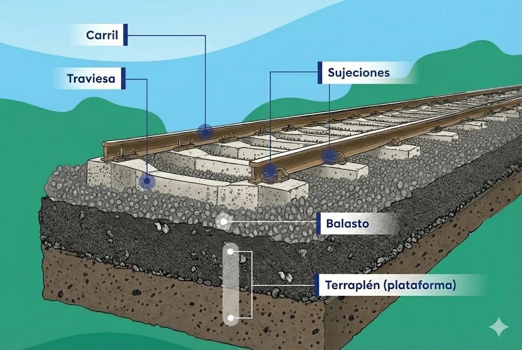
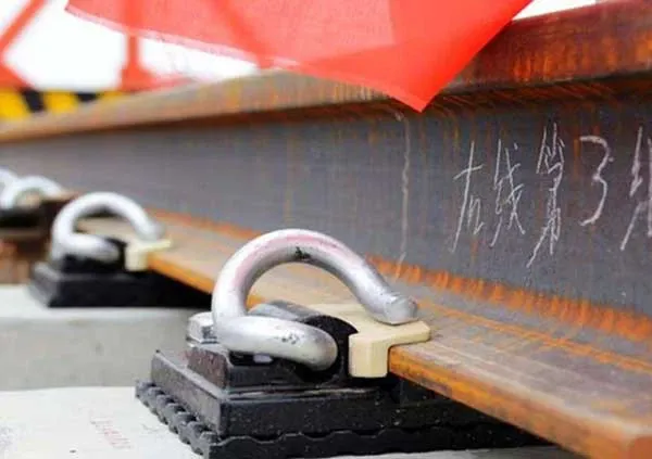
The superstructure deserves a more detailed analysis, as it is composed of several essential elements: two parallel rows of rails that provide the trajectory for the train wheels, sleepers (structural elements oriented transversely to the track axis that act as fastening elements for the rails) and ballast (the layer of granular material on which the sleepers rest, distributing loads towards the infrastructure). Complementarily, various auxiliary elements such as base plates, joint bars, fastening systems and other accessories are incorporated to ensure the cohesion of the complete system.
A notable aspect of railway evolution is that the basic configuration of the superstructure has remained practically invariable since the origins of the railway, demonstrating the solidity and effectiveness of the fundamental design.
I.2 Functions
Each component of the superstructure performs specific but interconnected functions that determine the integral behavior of the system.
The rail acts as the most structurally critical element, directly assuming the point loads transmitted by the wheels of the rolling stock. Its functions can be classified into two main categories:
-
Support function: the rail must safely absorb and transfer all efforts generated by the circulation of trains, performing this task with generally reliable performance under the foreseen design conditions.
-
Directive guidance function: through the interaction between the lateral flanges of the wheels and the specific geometry of the rail, vehicles are maintained on the correct trajectory. However, this guidance mechanism entails unwanted consequences, in particular the generation of significant friction between the rolling surfaces and the rail in curved sections, as well as between the flanges and the rails in both straight and curved alignments. This friction phenomenon constitutes one of the main causes of premature wear and problems associated with track maintenance and rolling stock conservation.
The sleepers, for their part, perform equally important structural functions: they maintain and guarantee the constant separation between the two rails (function known as lateral bracing) and act as transmission elements, channeling the efforts captured by the rails towards the underlying ballast layer.
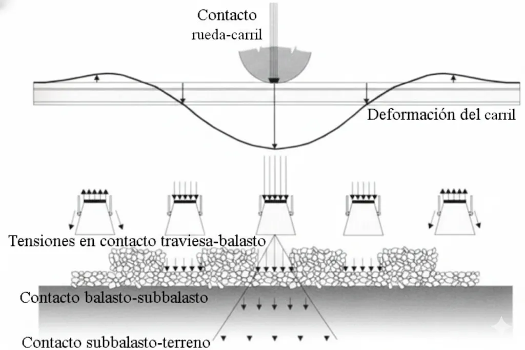 Structural behavior of the track system
- The ballast has the function of transmitting and distributing over the subgrade, as uniformly as possible, the loads of the trains and evacuating rainwater from the sleeper seat as quickly as possible.
- In addition, it will also be the function of the ballast to brace the sleepers by friction to avoid track displacement, form an elastic bed with them and allow the evaporation of water from the subgrade by capillarity.
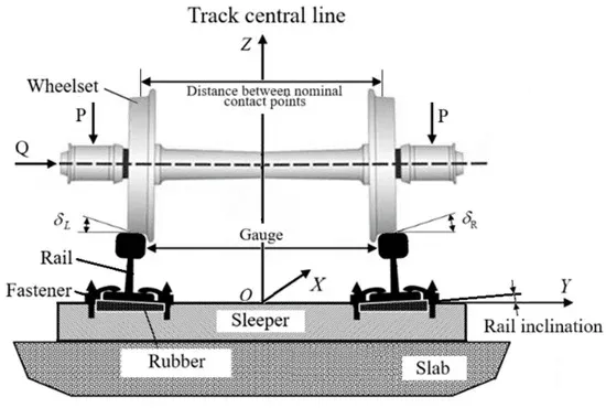
Chapter II Track Gauge
In the analysis of railway systems, the track gauge emerges as a fundamental dimensional parameter that conditions multiple aspects of both the design and the operation of the lines. This geometric characteristic is technically defined as the distance measured between the vertical internal planes of the rails, specifically in the contact zone with the wheels. To guarantee the precision of this measurement, it is conventionally established that the determination of the width must be carried out in a horizontal plane located at a depth of 15 mm (designated as \(z_p\)) below the running surface, which is the effective contact surface between the wheel and the rail.
The specification of the track gauge represents a transcendental design decision, since this dimension remains constant throughout the entire railway line in straight alignments, but can be strategically modified in curves to optimize the inscription of vehicles equipped with driving axles.
II.1 Types
The international track gauge adopted by most countries at the Bern Conference of 1907 and constitutes 61.5% of the world’s lines, has a value of \(4^{\prime}\) 8.5”, equivalent to \(\mathbf{1 . 4 3 5 ~ m m}\). This value is the minimum in straight alignment. In a curve, due to the problem of vehicle inscription, especially vehicles equipped with driving axles, a gauge widening is given as a function of the curve radius, the maximum being \(\mathbf{1 . 4 7 0 ~ m m}\). The value between rail axes is approximately 1,500 mm.
In Spain, the track gauge was fixed in the General Conditions Specification that was part of the Royal Order of December 31, 1844, drafted by the Civil Engineers Subercase and Santa Cruz. Said value was six Castilian feet. The equivalence to the decimal metric system is \(0.2786 \mathrm{~m}\) per Castilian foot, so the six feet are 1.6716 m. But as the first peninsular railway was the Barcelona-Mataró, built by the English, they stuck to their units and, looking for the closest equivalence in English measures, adopted the width of five English feet and six inches which, taken to the metric system gives: \((5 \cdot 0.3048)+ (6 \cdot 0.0254)=\mathbf{1 , 6 7 6 4} \boldsymbol{m}\). Therefore, a track gauge larger by \(4.8 \mathrm{~mm}\) than the official value resulted. Subsequently, RENFE adopted \(\mathbf{1 . 6 6 8} \mathrm{mm}\) to reduce the amplitude of the hunting oscillation.
- In Portugal, \(\mathbf{1 . 6 6 5}\) mm. In Argentina, Chile and a line in India, the adopted gauge is \(\mathbf{1 . 6 7 6 ~ m m}\). ( \(5^{\prime} 6^{\prime \prime}\) which is the gauge advocated by Rennie, versus the gauge defended by Stevenson 1,435 mm during the so-called Battle of the Gauges that ended with the Gauge Act of a Royal Commission in 1846). In Russia, 1,524 \(\boldsymbol{m} \boldsymbol{m}\).
- Other gauges are: The so-called narrow gauge or metric gauge with a value of \(\mathbf{1 . 0 6 7 ~ m m}\left(3^{\prime} 6^{\prime \prime}\right)\) or \(\mathbf{1 . 0 0 0 ~ m m}\).
- Also some mining or industrial tracks with values that in some cases reach up to 600 mm.
- We can say that the track gauge is a fundamental characteristic in both the layout and the operation of railway lines.

II.2 Advantages and Disadvantages
The adoption of narrow gauge versus broad gauge implies a careful analysis of both economic and operational factors. First, from the perspective of economic advantages, the implementation of narrow gauge presents compelling arguments:
The use of curves with smaller amplitude radii allows the infrastructure to adapt more flexibly to irregular topographies, minimizing the need for extensive earthworks compared to broad gauge configurations. The reduction of the subgrade width consequently generates lower volumes of embankments and cuts in ground preparation works. The construction of engineering structures such as tunnels and bridges results economically more favorable due to the decrease in their transverse dimensions. Rolling stock designed for narrow gauge requires a reduced loading gauge, implying significant savings in its manufacture. Superstructure components—ballast, shorter sleepers and rails with shorter total lengths due to the viability of smaller radii—all benefit from cost reductions. Finally, traction resistance in curves decreases notably, allowing increases in ramp gradients without compromising operability.
However, the operational disadvantages of narrow gauge with respect to broad gauge are significant from an operational perspective: traffic capacity is inherently limited by the reduced dimensions of the vehicles. Maximum operable speeds are lower due to dynamic stability limitations of rolling stock in narrower configurations. To maintain similar profitability, the operating ratio (ratio between operating expenses and income) experiences an increase as the track gauge decreases. Finally, there is the inherent difficulty of establishing operational connections with pre-existing standard gauge rail networks, complicating interoperability and the transit of rolling stock between systems.
II.3 Vehicle Design for Circulation on Both Track Gauges
Throughout the history of rail transport, the presence of multiple track gauge standards has generated specific operational needs. The Spanish company Transfesa developed an innovative solution approximately four decades ago to solve the challenge of exporting fresh Spanish products to European markets. This solution was based on the concept of the interchangeable axle wagon, which allowed the operational transition between systems of different gauges without requiring cargo transshipment.
This operating system, implemented in the logistics facilities of Hendaye and Cerbère, is based on a precise mechanical process: a set of high-capacity hydraulic jacks lifts the wagon box and its frame once the original axles have been disconnected. The original axles remain on the specialized changeover track, which has a dual configuration that houses both the Spanish and international gauges. Once the axles of the previous configuration are removed, axles designed for the international gauge are installed. Before allowing the wagon to descend onto the new axles, it is necessary to precisely reposition the brake shoes of the braking system. The fixation of the axles—which already incorporate their corresponding pre-installed grease boxes—is carried out through procedures that prioritize both safety and speed of operation.
The efficiency of this system demonstrates its operational advantages: compositions of twenty wagons can complete the axle change process in the course of just a few minutes, immediately remaining ready to continue their journey towards European destinations.
II.4 Axle Changers
II.5 Bogie Exchange
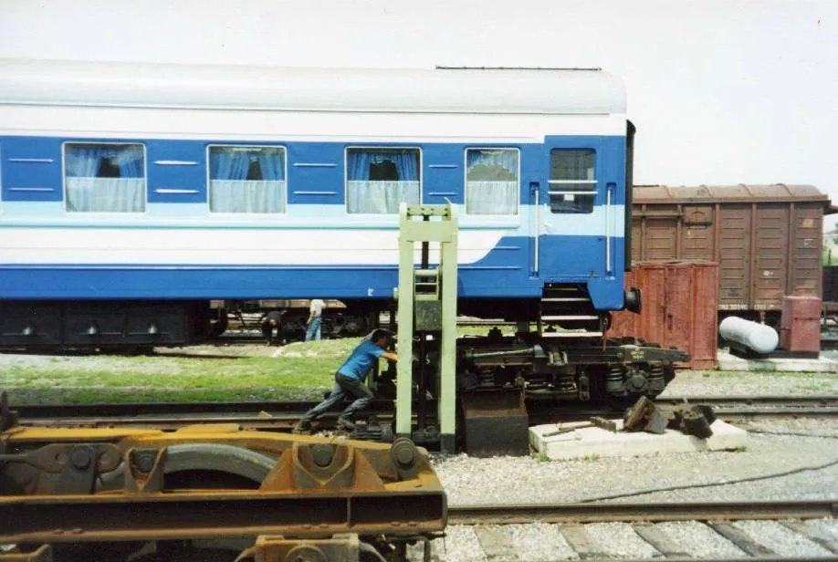
Lifting of locomotive S-334 for bogie exchange - Renfe
II.6 Talgo RD: Gauge Changer
- On November \(\mathbf{1 2}\), 1968, the Talgo Experimental with Variable Gauge made the historic Madrid-Paris trip without transshipment and, currently, various direct services are carried out with France, Switzerland and Italy. The system, which is economical, fast and simple, is based on the use of Talgo running gear with independent wheels, so it can only be applied to this type of cars.
- The system, in outline, consists of five operations:
- Unload the weight that gravitates on the wheel sets (operation equivalent to the systems previously exposed at the entrance to jacks).
- Unlock the wheel sets from the running gear bridge or frame (this operation is equivalent to lowering the axles).
- Transverse displacement of the wheel sets to the position corresponding to the new track gauge (this operation is equivalent to the removal of the axle and the approach of the new one).
- Locking of the wheel sets in their new position (equivalent to the installation of the new axle).
- Load the vehicle on its own running gear, operation inverse to point 1 (equivalent to the exit specific to jacks).
Talgo RD: variable gauge
Chapter III The Track Seat
The process of seating or establishment of the railway track constitutes a critical phase in the construction of railway infrastructures. During this procedure, which is also called laying or track laying, the structure must receive precise geometric dimensions. In straight alignment sections, the nominal track gauge is established through the rigorous positioning of the rails, ensuring that their inner faces maintain the prescribed separation. Conversely, in curvature zones, the track geometry is strategically modified by incorporating an additional gauge widening, a concept that will be examined in greater depth in later sections of this analysis.
The seating of the track
III.1 Rail Inclination
In the transverse geometric configuration of the rails, they are not arranged vertically but are intentionally inclined towards the inside of the track. This inclination pursues objectives of optimization of dynamic behavior and durability. In most European networks, the typical inclination is \(\mathbf{1/20}\), although there are notable regional variations: British railways traditionally implement an inclination of \(\mathbf{1/40}\), while in the United States inclinations of \(\mathbf{1/100}\) have been used, and even in some cases completely vertical rails.
Operational experience accumulated in Europe has shown that inadequate inclinations generate problematic wear pathologies: the analysis of the running surface reveals oblique wear that correlates directly with the inclination of the tires, accompanied by premature crushing on the inner part of the rail head and formation of harmful metal burrs. Simultaneously, abnormal wear of the tires is observed with the formation of deep grooves close to the lateral flanges. These degradation phenomena also generate an undesirable tendency for the rails to overturn towards the outside, simultaneously increasing the magnitude of the thrust of the outer rail on the screw spikes and sleepers, especially in sharp curves, which translates into significantly worse general track alignment quality.
For these reasons based on empirical observation, European railway administrations have firmly maintained the inclination of \(1/20\) as an operating standard. There is, however, a notable exception in High Speed lines in Germany and Japan, which have adopted the more moderate inclination of \(1/40\) to optimize dynamic behavior at extreme speeds and reduce the magnitude of lateral stresses on the superstructure.
III.2 Track Gauge Tolerance
Although construction standards specify the need to establish an absolutely precise track gauge during track laying in straight alignments, operational reality is significantly far from this theoretical ideal. Defects inherent in construction processes combined with the cumulative effects of train circulation generate deviations from the nominal gauge, manifesting in the form of gauge widening or tightening of the track. These variations constitute a practically inevitable phenomenon in railway operation.
Gauge widening can manifest indiscriminately in wooden or concrete sleepers, presenting a multiplicity of generating causes:
a) Erosion and loss of material from the rail head on its inner surface, product of continuous contact with wheel tires.
b) Progressive deterioration of the screw spike body through abrasion mechanisms caused by rubbing of the rail foot end during repetitive load and vibration cycles.
c) Plastic deformation and buckling of screw spikes under the combined action of vertical and horizontal loads.
d) Cracking and splitting of wooden sleeper material, generated by wetting and drying cycles, as well as repetitive impacts.
e) Functional deterioration of the elastic rail fastening system to the sleeper, including loss of pretension of fastening elements and degradation of elastomeric elements.
Tightening, which occurs exclusively in straight alignments, obeys multifactorial etiologies, being notable the progressive accentuation of the rail foot inclination (phenomenon induced by the natural conicity of the wheel tire during repetitive wear cycles), curvature induced in wooden sleepers by deficiencies in their chemical preservation or by variations in their moisture content, and yielding of the central section of the sleeper under complex stresses.
In response to this operational reality, a hierarchical system of geometric tolerances has been developed ranging from criteria applicable at the time of new work reception to critical alarm limits that prohibit circulation. The tolerances specifically linked to the track gauge parameter according to NAV 7-1-3.7 are specified below:
New track tolerances: These parameters are prescribed in technical specifications for new track construction, establishing limits of \((+3 \mathrm{~mm} \cdot -2 \mathrm{~mm})\) with respect to the nominal value.
Service or good riding tolerances: These dimensional margins define the permissible variation range in geometric track parameters during normal operation, fixed at \((+6 \mathrm{~mm}-3 \mathrm{~mm})\) of the design value.
Speed limit tolerances: When these levels are exceeded, the need to implement restrictions on the train operating speed is activated until the track is restored to geometrically acceptable conditions.
Safety tolerances: These constitute critical dimensional variation limits beyond which risk conditions for safe train operation are established. The determination of these thresholds depends not exclusively on track characteristics, but also on rolling stock parameters including its typology, specific dynamic characteristics and general state of conservation.
Alarm indicator tolerances: Upon exceeding these levels, an operational alert signal is generated demanding immediate restoration of nominal geometric track characteristics in the affected segment.
Maintenance tolerances: These values are enforceable during quality control activities in track maintenance and repair work, fixed at \((+4 \mathrm{~mm}-3 \mathrm{~mm})\) with respect to original design.
Geometric auscultation tolerances in general track
| Alert Level (AL): | Peak Gauge (mm) | Peak Gauge+ (mm) | Gauge 100 m (mm) | Gauge 100 m+ (mm) | Twist 3 m (mm/m) | Transv Level D1 (mm) | Long. Level D1 (mm) | Align. D1 (mm) | ||
|---|---|---|---|---|---|---|---|---|---|---|
| Standard | Iberian | Standard | Iberian | |||||||
| \(V \leq 80\) | -7 | -7 | 25 | 25 | -6 | 25 | 4 | 10 | 21 | 17 |
| \(80 < V \leq 120\) | -7 | -7 | 25 | 20 | -5 | 16 | 4 | 8 | 18 | 15 |
| \(120 < V \leq 160\) | -6 | -6 | 25 | 18 | -3 | 16 | 4 | 7 | 15 | 12 |
| \(160 < V \leq 200\) | -4 | -4 | 20 | 16 | -3 | 16 | 4 | 6 | 12 | 10 |
| \(200 < V \leq 230\) | -4 | -3 | 20 | 14 | -3 | 16 | 3 | 5 | 12 | 8 |
| \(230 < V \leq 300\) | -3 | -2 | 20 | 10 | -1 | 16 | 3 | 4 | 10 | 7 |
| \(300 < V \leq 360\) | -3 | -1 | 20 | 9 | 0 | 16 | 3 | 3 | 8 | 6 |
Table 1.- Geometric parameters for standard and Iberian gauge with AL levels.
| Alert Level (AL): | Alignment D1 (mm) | Alignment D2 (mm) | ||||||||
|---|---|---|---|---|---|---|---|---|---|---|
| A | B | C | D | E | A | B | C | D | E | |
| \(V \leq 80\) | 12 | 14 | 14 | 14 | 15 | - | - | - | - | - |
| \(80 < V \leq 120\) | 8 | 10 | 10 | 10 | 11 | - | - | - | - | - |
| \(120 < V \leq 160\) | 6 | 8 | 8 | 8 | 9 | - | - | - | - | - |
| \(160 < V \leq 200\) | 5 | 7 | 8 | 8 | 8 | 10 | 12 | 14 | 14 | 14 |
| \(200 < V \leq 230\) | 5 | 6 | 8 | 8 | 8 | 10 | 12 | 14 | 14 | 14 |
| \(230 < V \leq 300\) | 4 | 5 | 7 | 7 | 7 | 8 | 9 | 10 | 10 | 10 |
| \(300 < V \leq 360\) | 3 | 4 | 6 | 6 | 6 | 6 | 7 | 8 | 8 | 8 |
Table 2.- Alignment by line type according to Network Statement (A, B, C, D or E) \({ }^{3}\) with AL levels.
| Alert Level (AL) | Longitudinal Leveling D1 (mm) | Longitudinal Leveling D2 (mm) | ||||||||
|---|---|---|---|---|---|---|---|---|---|---|
| A | B | C | D | E | A | B | C | D | E | |
| \(V \leq 80\) | 12 | 16 | 16 | 17 | 18 | - | - | - | - | - |
| \(80 < V \leq 120\) | 10 | 12 | 12 | 14 | 16 | - | - | - | - | - |
| \(120 < V \leq 160\) | 8 | 10 | 10 | 13 | 15 | - | - | - | - | - |
| \(160 < V \leq 200\) | 7 | 9 | 12 | 12 | 12 | 12 | 14 | 16 | 16 | 16 |
| \(200 < V \leq 230\) | 7 | 8 | 12 | 12 | 12 | 12 | 14 | 16 | 16 | 16 |
| \(230 < V \leq 300\) | 6 | 7 | 10 | 10 | 10 | 8 | 10 | 12 | 12 | 12 |
| \(300 < V \leq 360\) | 6 | 6 | 8 | 8 | 8 | 8 | 9 | 10 | 10 | 10 |
Table 3.- Longitudinal leveling by line type according to Network Statement ( \(A, B, C, D\) or E) \({ }^{3}\) with AL levels.
Geometric auscultation tolerances in non-general tracks
For non-general tracks (secondary tracks, sidings, etc.) the parameters to consider are the following:
| Alert Level (AL): | Peak Gauge (mm) | Peak Gauge+ (mm) | Gauge 100 m (mm) | Gauge 100 m+ (mm) | Twist 3 m (mm/m) | Transv Level D1 (mm) | Long. Level D1 (mm) | Align. D1 (mm) |
|---|---|---|---|---|---|---|---|---|
| \(V \leq 40\) | -8 | 29 | -7 | 25 | 5 | 12 | 21 | 17 |
| \(40 < V \leq 80\) | -7 | 25 | -6 | 25 | 4 | 10 | 18 | 15 |
Table 4.- AL Levels for non-general tracks.
Geometric auscultation tolerances in tracks with mixed traffic
Additionally, for tracks with mixed traffic:
| Alert Level (AL) | Twist 5 m (mm/m) | Twist 9 m (mm/m) | Gauge Var D1 (mm/m) |
|---|---|---|---|
| \(V \leq 80\) | 4 | 3,1 | 9 |
| \(80 < V \leq 120\) | 4 | 3,1 | 8 |
| \(120 < V \leq 160\) | 4 | 3,1 | 7 |
| \(160 < V \leq 200\) | 4 | 3,1 | 6 |
| \(200 < V \leq 230\) | 3 | 3 | 5 |
| \(230 < V \leq 300\) | 3 | 3 | 4 |
| \(300 < V \leq 360\) | 3 | 3 | 3 |
Table 5.- AL Levels for tracks with mixed traffic.
Geometric auscultation tolerances in metric gauge tracks
For metric gauge tracks the parameters will be as follows:
| Alert Level (AL) | Peak Gauge (mm) | Peak Gauge+ (mm) | Gauge 100 m (mm) | Gauge 100 m+ (mm) | Twist 3 m (mm/m) | Transv Level D1 (mm) | Long. Level D1 (mm) | Align. D1 (mm) |
|---|---|---|---|---|---|---|---|---|
| \(V \leq 60\) | -6 | 20 | -5 | 18 | 4,5 | 11 | 18 | 16 |
| \(60 < V \leq 80\) | -6 | 20 | -5 | 15 | 4 | 10 | 16 | 14 |
| \(80 < V \leq 120\) | -6 | 15 | -5 | 10 | 4 | 8 | 12 | 10 |
Table 6.- AL Levels for RAM.
III.3 Number and Placement of Sleepers
The sleeper density along the track constitutes a design parameter of considerable operational importance. There is a direct relationship between greater concentration of sleepers and improvement in rolling quality; simultaneously, increased sleeper density significantly reduces the tendency of the supporting subsoil to experience differential movements that would compromise the geometric stability of the track. Sleepers are oriented perpendicularly to the longitudinal axis of the track, maintaining this arrangement in both straight alignments and curved sectors. Sleeper density varies considerably in operational practice, ranging between \(\mathbf{1.000 ~ sleepers/km}\) in lines of lesser importance and \(\mathbf{2.000 ~ sleepers/km}\) in high traffic lines, this variation being a function of multiple parameters including load levels the structure must withstand, operating speeds, traffic volume importance, and in curved sectors, the radius of curvature characterizing said sections.
In specialized railway track terminology, joint sleeper is designated as that which is positioned immediately contiguous to the ends of individual rails, while consecutive sleepers are called shoulder sleepers. The essential characteristic of these special sleepers is their reduced spacing compared to the rest of the structure, a measure that is critical for structural stability. Partial or deficient application of this concentration principle leads to harmful phenomena: free ends of rails experience progressive sinking under repetitive loading if spacing is excessive, while if spacing is reduced excessively, an inverse phenomenon of rail end lifting is observed, again compromising prescribed geometry.

III.4 Joint Position
The union between rails, called joint, constitutes a geometric characteristic of fundamental technical relevance in the dynamic behavior of the railway track. Except for modern sections of welded track that have eliminated this discontinuity through metallurgical procedures, the joint inevitably represents a continuity solution in the rolling path, introducing perturbations in the trajectory of wheels circulating on the structure.
III.5 Concordant Joints
The spatial arrangement of joints between the two rails of a track constitutes an engineering decision that significantly impacts the dynamic behavior of the system. When the joints of one rail do not coincide positionally with those of the parallel rail, this arrangement is designated as staggered joints. In this configuration, typically the joint of one rail is located in correspondence with the midpoint of the adjacent rail, thus distributing stresses more sparsely along the structure. This procedure enjoys greater diffusion in North America than on the European continent. Even some US railway administrations have adopted more radical procedures, such as the so-called hit-or-miss system, which dispenses with regular criteria in joint placement, positioning rails without systematic reference to existing joint geometry. Other railway administrations have adopted as a criterion the placement of joints in correspondence with the spacing of vehicle bogie drive axles.
III.6 Comparison of the Two Joint Systems
Technical railway literature documents the existence of defenders for both joint positioning configurations, each offering differentiated operational advantages. In the concordant joints configuration, dynamic impact magnitudes generated at joint transitions are of greater amplitude, although their incidence is less frequent along the vehicle’s path. Conversely, with staggered joints, dynamic impacts are of lesser magnitude in each individual event, but are generated with considerably greater frequency. Additionally, when joints are staggered, gyroscopic effects derived from differential misalignment between wheels acquire higher magnitudes, potentially compromising vehicle dynamic stability. From a ride comfort perspective, the concordant joints configuration produces notably smaller transverse oscillations of rolling stock compared to staggered arrangement, a circumstance favoring rolling quality and passenger comfort.
III.7 Short Rails
In curved sectors of the track, fundamental geometric challenges emerge derived from the difference in arc lengths traveled by outer and inner rails. The longitudinal development of the rail located in the outer position of the curve substantially exceeds that of the inner rail. This circumstance prevents maintenance of joint concordance between both rail rows if uniform length segments are used. The technological solution to this challenge consists of introducing shortened rails strategically compensated in the inner thread, thus allowing joints to remain concordant along both rows. To analyze this geometric phenomenon, consider the following fundamental relationship between rail lengths:
\[\frac{\mathrm{L}}{\mathrm{~L}^{\prime}}=\frac{\mathrm{R}+\frac{\mathrm{a}}{2}}{\mathrm{R}-\frac{\mathrm{a}}{2}}\]From this expression, it is possible to derive the differential relationship:
\[\frac{L-L^{\prime}}{L}=\frac{\left(R+\frac{a}{2}\right)-\left(R-\frac{a}{2}\right)}{R+\frac{a}{2}}=\frac{a}{R+\frac{a}{2}}\]Developing this equation algebraically:
\[L-L^{\prime}=L \frac{a}{R} \Rightarrow L^{\prime}=L \cdot\left(1-\frac{a}{R}\right)\]Where \(L\) represents the nominal length of the outer rail, \(L'\) the reduced length of the inner rail, \(R\) denotes the radius of curvature, and \(a\) is the track gauge. This formulation allows precise determination of length reduction required to maintain geometric joint concordance in curves.
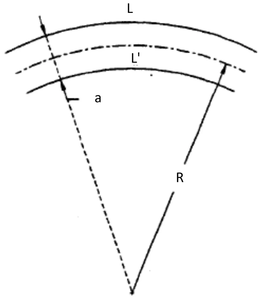 Length difference between inner and outer rail
It is worth noting the significant influence that the track gauge exerts on these geometric calculations, a factor that ultimately determines the corrections required in rail lengths.
III.8 Curves
| Minimum Radii | Standard Gauge | Secondary Tracks |
|---|---|---|
| Normal Lines | 300 m | 150 m |
| 1 m Gauge | 100 m | 60 m |
| 0.75 m Gauge | 80 m | 40 m |
| Coefficient K | 4.5 | 3.8 | 2.5 |
|---|---|---|---|
| Radius | Curves with Superelevated Transition | Curves without Superelevated Transition | Non-Superelevated Curves |
| 200 m | 64 km/h | 55 km/h | 37 km/h |
| 300 m | 78 km/h | 65 km/h | 45 km/h |
| 400 m | 90 km/h | 76 km/h | 52 km/h |
| 500 m | 101 km/h | 85 km/h | 58 km/h |
| 900 m | 135 km/h | 114 km/h | 78 km/h |
| 1000 m | 142 km/h | 120 km/h | 82 km/h |
The determination of the minimum geometric radius that can be adopted in curved sectors of a railway line maintains a close correlation with the track gauge, as demonstrated in the preceding analysis. Minimum limits generally adopted by different railway administrations are synthesized in the previous tables.
As will be developed in greater depth in later chapters, the interrelation between operating speed and radius of curvature acquires a specific mathematical expression, characterized by the following formulation:
\[V=K \cdot \sqrt{R}\]Where \(V\) represents the maximum permissible speed expressed in kilometers per hour, \(R\) denotes the radius of curvature measured in meters, and \(K\) constitutes a characteristic coefficient that varies as a function of multiple parameters including the specific radius of the curve and particularly the presence or absence of superelevation in the transverse geometry of the track. Specific values of coefficient \(K\) for different curve configurations are detailed in the attached reference tables.
III.9 Gradients
The longitudinal profile of a railway track constitutes a design element requiring detailed analysis of its slope characteristics. In evaluating these profiles, the configuration of gradients (ramps), i.e., elevation changes along the route, is systematically considered.
In lines of general character and strategic importance, railway designers seek to maintain slopes within ranges not exceeding \(\mathbf{10 ~ mm}\) per meter, considered as a reference limit for conventional applications. Statistical analyzes of railway networks in this category show that typically between \(70\%\) and \(80\%\) of total track length presents slopes below this reference value. However, in regions of particularly rugged topography, situations requiring significant deviations from these parameters arise. In mountainous territories, it is common to find gradients of the order of \(\mathbf{20 ~ mm}\) per meter, a frequent figure especially in a large proportion of Spanish railway lines crossing orographically complex zones. Spanish alpine regions present slopes of up to \(25 ~ mm\) per meter, a magnitude constituting the upper limit recommended for lines powered by steam traction, a technology presenting inherent limitations in its capacity to overcome steeper inclinations.
There are, however, historically notable exceptions where these conventional limits have been reached or exceeded. The celebrated European Alpine lines of Mont Cenis and Arlberg incorporate slopes of \(\mathbf{30 ~ per ~ thousand}\) in their layouts, limits rarely reached in contemporary designs. The Giovi line crossing the Apennine mountain range reaches slopes of \(\mathbf{3 5 ~ per ~ thousand}\), a figure approaching extreme technical viability maximums. There is an additional exceptional case in the trans-Pyrenean line interconnecting Ripoll-Puigcerdá-Ax les Thermes, which commercially exploits with electric traction to overcome orographic obstacles that dispensed with conventional traction limitations. This line incorporates gradients of \(\mathbf{41 ~ per ~ thousand}\) on its Spanish slope and \(\mathbf{43 ~ per ~ thousand}\) on the French side, demonstrating technical possibilities that modern electric traction technologies allow to overcome compared to steam systems.
Chapter IV Track Characteristics
The railway track, conceived as an integrated complex system, must simultaneously satisfy three fundamental interrelated requirements defining its behavior in operation: structural resistance, elastic flexibility, and geometric continuity. These three attributes characterize system performance in its entirety.
IV.1 Resistance
The resistance characteristic is indispensable to guarantee that the track will not experience significant permanent deformations, both in its plan geometry (horizontal deviations) and in its longitudinal profile (vertical deviations), when subjected to the action of loads generated by traffic. The track must maintain its dimensional integrity under repetitive mechanical stress cycles inherent to continuous operation.
IV.2 Flexibility
The characteristic of flexibility or elasticity of the track emanates from the fundamental technical need that the structure should not constitute a rigidly undeformable assembly. Such absolute rigidity would cause the generation of violent and concentrated dynamic reactions upon passage of loads over the structure, with harmful consequences for system integrity.
This conceptual distinction establishes a radical difference between railway track and road structures. A road superstructure could, in theory, be designed as a perfectly rigid element, given that vehicles circulating on it possess comparatively light weights with respect to railway material, and are equipped with suspension systems provided with elastic tires that effectively absorb impacts derived from pavement irregularities. The tire of a road vehicle performs a critical damping function, dissipating kinetic energy and impact. Conversely, railway track must be capable of improving rolling stock of considerable weight provided with rigid metal tires lacking any elastomeric capacity. This reality imposes the need for the track structure itself to present controlled elasticity, allowing it to adapt to small irregularities or discontinuities of the surface without transmitting destructive impacts. When a geometric irregularity of just a few millimeters in height (exemplified by the unevenness corresponding to the plane of a wheel) is traversed by a heavily loaded axle moving at high speed, stresses generated on the track reach extraordinary magnitudes if the structure does not possess sufficient elasticity to partially absorb the impact event. Both characteristics—structural robustness and elasticity—present an intrinsic antagonism that must be resolved through an engineering balance. To date, this optimal compromise has not been achieved in a manner superior to that achieved by conventional track on sleepers and ballast, eloquent demonstration of classic design efficacy.
Values of unsprung masses stressing the track constitute a notable differentiation parameter between European and US railway systems. Axle load specifications vary substantially: while in Europe maximum normal admitted load is in the \(20-22\) tons per axle range, in North America normal operating values reach \(30\) to \(32\) tons per axle. There are even examples of strategically important North American lines, such as the Pennsylvania Railway, that have designed their superstructure to withstand loads of up to \(43.5\) tons per axle, a figure approaching approximately quadruple European standards of the era.
Currently, one of the central challenges of track engineering consists of achieving a design configuration that is simultaneously sufficiently rigid to withstand extreme loads on unsprung components, and simultaneously capable of absorbing complex vibrations originated by circulation at elevated speeds. This engineering dilemma seeks to produce a smooth ride that significantly attenuates transmission of dynamic shocks and noises towards rolling stock and its occupants, improving both operational safety and comfort.
IV.3 Continuity
An equally essential operational characteristic of railway track is its geometric continuity, both in horizontal dimension (plan continuity) and vertical dimension (profile continuity). The track, defined by its layout in plan and its longitudinal profile, inherently constitutes a fundamentally discontinuous geometric entity, not only due to physical discontinuity proper to rails when not welded (substantially remedied in modern tracks by welding guaranteeing total metallurgical continuity), but also by the fact that it is composed of successive sections presenting differentiated longitudinal inclinations and variable radius curves.
Achieving this continuity must be reached not only from a static geometry perspective, but also from a dynamic analysis of system response under operating conditions. This implies fundamental need for characteristic elasticity and flexibility of track to be uniform along its entire extension, remaining invariant under passage of dynamic loads, avoiding abrupt perturbations in mechanical properties of structure.
Presence of vertical discontinuities in track geometry, commonly called track potholes, can give rise to severe transient dynamic events. When a mounted axle of rolling stock experiences vertical displacement derived from geometric irregularity, instantaneous acceleration of axle occurs as inertial response. This dynamic event can have significant harmful consequences: passengers experience abrupt comfort variations, rolling stock integrity is compromised by unexpected mechanical stresses, and operational safety may be affected in extreme situations.
Chapter V Material Characteristics
V.1 Keying/Setting (Calaje)
Unlike road transport vehicles, where wheels are mounted freely on axles, railway vehicles present a radically different configuration in their rolling system. In railways, wheels are permanently coupled to their corresponding axles, constituting a solidary rigid unit rotating as integral assembly. This design architecture confers superior structural solidity compared to technological alternatives, since a wheelset manufactured as single integral piece presents lower susceptibility to dislocation or detachment phenomena compared to configurations where wheels are freely mounted on inner bearings. This advantage is of particular importance when railway material must withstand extreme loads and circulate at elevated speeds, conditions where structural robustness is critical.
However, this constructive configuration entails unfavorable operational consequence manifesting mainly in curved sectors. When a complete axle circulates through a curve, wheel positioned on outside of turn travels greater arc-linear distance than inner wheel. Due to rigid coupling between both wheels to common axle, outer wheel must simultaneously roll and slide on outer rail to compensate for arc development difference. This combined rolling and sliding movement generates significant friction between contact surfaces, producing accelerated wear of both tire and rail, increasing maintenance costs and limiting operational life of both components.
V.2 Wheel Rim Shape
The contact surface geometry between wheel and rail constitutes element of fundamental importance in dynamic behavior of railway system. Rolling surface of tire is not cylindrical as might be intuitively expected, but belongs to conical surface whose vertex is located in position exterior to track subgrade. This conical arrangement is analogous to geometry shown in Figure 10, where conicity angle has been exaggerated for illustrative purposes; in practice, this angle is typically \(1/20\) (five degrees inclination). This conical geometry of tires provides two differentiated but complementary operational functions: first, it acts functionally as mechanical differential automatically compensating arc development differences between outer and inner wheel in curved sectors; second, it contributes to lateral guidance of wheelset, completing trajectory control mechanisms in straight alignments through interaction between wheel flanges and rail geometry.
Chapter VI Mixed Characteristics
Mixed characteristics are designated as those geometric and functional properties jointly defined by track parameters and vehicle characteristics in interdependent form, where specification of one requires information from other. This category includes those characteristics whose presence in track is technical requirement imposed by properties of rolling stock circulating on it. Paradigmatic examples of these mixed characteristics include track clearance and gauge widening, both inherently linked to dynamic and geometric interaction between vehicle and infrastructure.
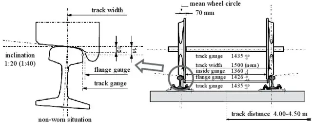
Running Plane: Defined as rail rolling surface effectively found in physical contact with wheel tire during operation.
Rolling Circle: Designated as cross-section of rolling surface resulting from intersection with vertical plane oriented at specific distance of \(70 ~ mm\) measured from inner face of wheel flange, thus constituting normalized geometric reference for measurements.
Track Play/Clearance: Track play is understood as free space intentionally left between wheel lateral flange and rail inner face, allowing these components not to be in continuous contact, thus avoiding constant wear by friction that would compromise durability. Technically defined as difference existing in straight alignment between separation of inner planes of rails and distance between outer edges of wheel flanges, this measurement being performed in plane at \(10 ~ mm\) below running plane. Concept of track play is operationally critical: if clearance were excessively large, sinusoidal movement of wheelset could acquire amplitude resulting in unstable and potentially dangerous dynamic running, with increase of wheel-rail attack angle to unacceptable magnitudes. Conversely, if play were very reduced or null, highly harmful constant friction would occur.
Considering scenario of new rails, track play will be direct function of progressive wear of wheel flanges. At height of \(10 ~ mm\) below running plane, flanges can present variable thickness, ranging between \(30 ~ mm\) in new wheel condition and \(22 ~ mm\) when limit of permissible wear before removal has been reached.
VI.1 Track Play/Clearance
Consequently, for same operating track, available play varies substantially according to wear state of rolling stock. If circulating with new tires, play will be \(J\), while if operation is performed with worn tires, available play will increase by:
\[\mathrm{J}+2^{\star}(30-22)=\mathrm{J}+16 \mathrm{~mm}\]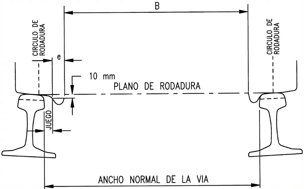
Normalized methodology for track play measurement is expressed by algebraic relationship:
\[\mathrm{J}=\mathrm{G}-\mathrm{B}-2^{*} \mathrm{e}\]where \(G\) represents nominal track gauge, \(B\) is distance between inner planes of rails (wheelset back-to-back distance), and \(e\) is flange thickness.
For Iberian gauge specifically:
\[\mathrm{J}=1668-1596-2^{*} 30=12 \mathrm{~mm}\]For new wheels; when extreme tire wear conditions are reached, this value increases to:
\[\mathrm{J}=28 \mathrm{~mm}\]Difference of \(16 ~ mm\) additional with respect to new tires.
For international track gauge:
\[\mathrm{J}=1435-1366-2^{*} 30=9 \mathrm{~mm}\]Initial value with new wheels; upon reaching maximum permissible wear:
\[\mathrm{J}=25 \mathrm{~mm}\]Rolling circle cross-section, defined by \(70 ~ mm\) reference from inner face of flange, provides characteristic dimensional values:
For Iberian gauge:
\[1596+2^{*} 70=1736 \mathrm{~mm}\]For international gauge:
\[1435-9-2^{*} 30+2^{*} 70=1506 \mathrm{~mm}\]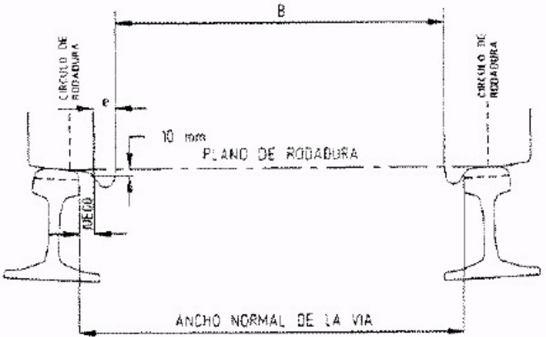
VI.2 Gauge Widening
In vehicle operation over curved sectors, additional geometric stresses arise that do not present in straight alignments. Rigid structural configuration of vehicle frame combined with mechanical characteristics of wheelset generates need for additional lateral space beyond conventional track play. This additional space is called gauge widening. For these reasons, when describing behavior in curves, concept of total play is introduced, expressed as:
\[J_{t}=J+S\]where \(J_t\) represents total available play, \(J\) is track play in straight alignment, and \(S\) is required gauge widening.
In context of Spanish railway infrastructure, standardized values for gauge widening have been established via technical standards as function of radius of curvature:
- In curves with radius between \(300\) and \(400 ~ m\): gauge widening of \(10 ~ mm\)
- In curves with radius between \(200\) and \(300 ~ m\): gauge widening of \(13 ~ mm\)
- In curves with radius less than \(200 ~ m\): gauge widening of \(18 ~ mm\)
At international scale, International Union of Railways (UIC) has proposed and validated empirical formulas relating required gauge widening with specific radius of curvature:
\[S=\frac{6}{R}-0,012 \quad \text { If } R \geq 500 \mathrm{~m} \rightarrow \mathrm{~S}=0\]Alternatively, additional formulation is available:
\[\text { } S=\frac{(1000-R)^{2}}{27000} \quad \text { If } R \geq 1000 \mathrm{~m} \rightarrow S=0\]Substantial difference in design philosophies between continents is observed: in Europe, implementation of relatively reduced track play combined with generous gauge widening values in curves is characteristic. Conversely, in United States, design approach inverts these priorities, using wider track play with more conservative gauge widenings.
Chapter VII Admissible Axle Loads
Specification of load capacity of railway infrastructure constitutes fundamental parameter determining line categorization and operational possibilities. International Union of Railways (UIC) has established systematic classification system categorizing tracks based on peculiar structural characteristics, including parameters such as rail weight expressed per unit length and relative distance between sleepers. Historically, three fundamental categories were initially established:
Category A: Lines with maximum load capacity of \(16 ~ t/axle\) Category B: Lines with maximum load capacity of \(18 ~ t/axle\) Category C: Lines with maximum load capacity of \(20 ~ t/axle\)
In turn, each of these primary categories (designated as \(X\), where \(X\) can be A, B or C) is subdivided into five subgroups \((X_1, X_2, X_3, X_4, X_5)\) characterizing resistant capacity of engineering structures such as bridges and viaducts. These subgroups are determined by quotient of total vehicle weight divided by total length measured between buffers:
- \[X_{1}=5 ~ t/m\]
- \[X_{2}=6.4 ~ t/m\]
- \[X_{3}=7.2 ~ t/m\]
- \[X_{4}=8 ~ t/m\]
- \[X_{5}=8.8 ~ t/m\]
VII.1 Track Classification
Since November 2004, UIC implemented revised and expanded classification incorporating new categories reflecting evolution of transport technologies and load intensification:
| Maximum load per | ||
|---|---|---|
| Line Category | Axle (tm) | Unit Length (tm/m) |
| A | 16 | 4.8 |
| B 1 | 18 | 5.0 |
| B 2 | 18 | 6.4 |
| C 2 | 20 | 6.4 |
| C 3 | 20 | 7.2 |
| C 4 | 20 | 8.0 |
| D 2 | 22.5 | 6.4 |
| D 3 | 22.5 | 7.2 |
| D 4 | 22.5 | 8.0 |
| E 4 | 25 | 8.0 |
| E 5 | 25 | 8.8 |
This updated classification reflects both increase in axle loads observed in modern systems and variability of demands according to infrastructure characteristics and operational utilization.
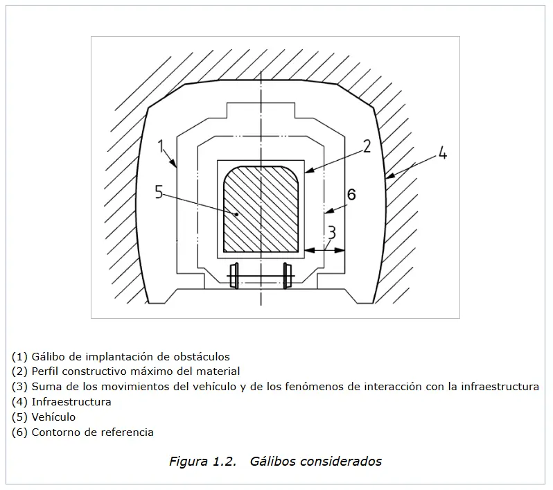
Chapter VIII Gauges
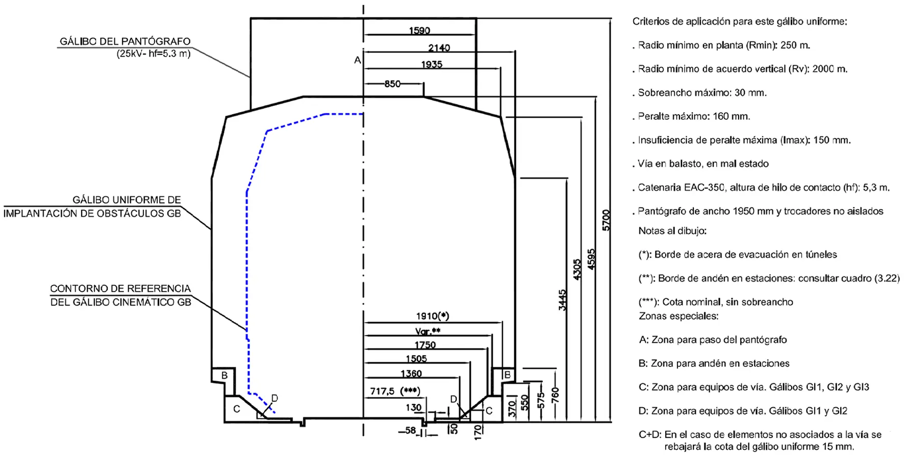
Concept of gauge in railway engineering is defined as maximum transverse profile that rolling stock can possess so as not to cause collisions or interferences with track and associated structures. This definition comprises all installations bordering or crossing track, including station subgrades, track switching devices (switches), bridges and viaducts, transport tunnels, signaling posts, and all other lateral infrastructure. Gauge thus constitutes envelope ensuring rolling stock circulates without risk of impact with external elements.
PPI Gauge (Passe-Partout International): Designated as static load gauge corresponding to specific vehicle position, constituting maximum profile permitted under rest conditions.
Order FOM/1630/2015, of July 14, approving the “Railway Gauge Instruction”
In 1973, International Union of Railways (UIC) established standardized gauge classification, designated by letters A, B and C. This classification allows harmonizing international standards and facilitating cross-border traffic. Attached table synthesizes main characteristics and commercial load possibilities associated with each gauge:
TABLE 7.1. MAIN CHARACTERISTICS AND LOADING POSSIBILITIES OF GAUGES A, B AND C
| Gauge | Width \(y\) height of gauge ( \(m\) ) | Loading possibilities | Width \(y\) height of load (m) | ||
|---|---|---|---|---|---|
| A | 3.15 | 4.32 | on container wagons. | 2.44 | 2.61 |
| Semi-trailers on pocket wagons | 2.50 | 3.57 | |||
| B | 3.15 | 4.32 | Swap bodies on normal container wagons. | 2.50 | 2.90 |
| Semi-trailers on pocket wagons | 2.50 | 3.80 | |||
| C | 3.15 | 4.65 | Semi-trailers and trucks with road gauge on low-floor wagons | 2.60 | \(4.00 \mathrm{~m}\) |
In 1986, French railway administration developed improved variant of gauge B, designated as gauge B+, which allowed increasing dimensions of transportable load. Gauge B+ allowed transport of larger swap bodies (\(2.6 ~ m\) wide by \(3 ~ m\) high) and semi-trailers transported in pocket wagons with dimensions of \(2.6 ~ m\) by \(3.9 ~ m\), substantially expanding operational possibilities compared to conventional gauge B.
VIII.1 Load Gauge A, B AND C
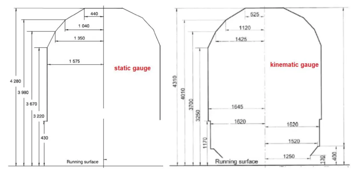 UIC static and kinematic gauge
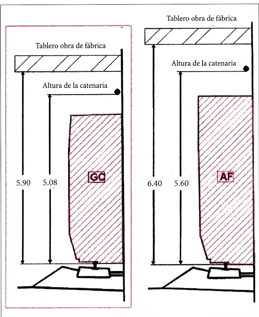
In planning of new railway infrastructures, gauge C is preferably adopted for newly constructed lines, providing maximum cargo transport possibilities. For those specialized lines where mixed traffic operation is contemplated combining high-speed services for passengers with freight train circulation, improved gauge is specified allowing transport of conventional trucks mounted on special wagons. This elevated gauge receives designation of AF gauge (corresponding to railway motorway/autopista ferroviaria), conceptually designed to maximize operational utilization of infrastructure through combination of transport modalities.
VIII.2 Track Spacing
In double track or multiple track railway systems, it is inevitable that situation arises where two trains circulate simultaneously on adjacent tracks in same cross-section of line. This operational configuration introduces technical need to specify minimum horizontal distance that must exist between axes of two contiguous tracks. This geometric parameter is designated as track center distance, defined as distance measured in transverse direction between axes of two adjacent tracks belonging to double track line or higher. It is important to note that technical nomenclature differs between administrations: some designate track spacing as this complete parameter \(E\), while denominating inter-track (entrevía) as component partial distances \(e\) and \(e'\), as illustrated in figure 35.
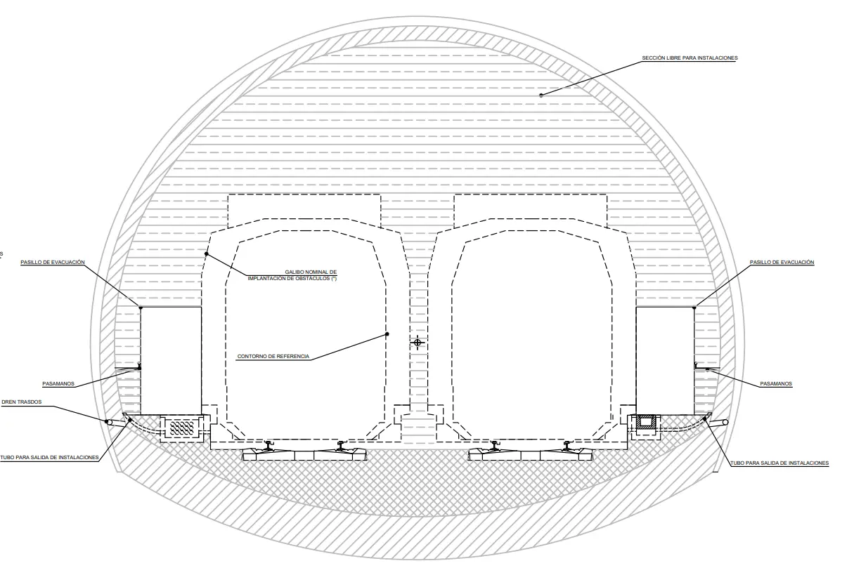 Tunnel gauge for double track
In rectilinear plan layouts, track spacing can remain constant along entire extension of track, except at specific points where increasing its value is required. Increases in track spacing are typically justified by need to install station subgrades in intermediate zone between two tracks, or by existence of individual engineering structures (e.g., bridge piers) requiring differentiated space for each track.
In straight alignment, minimum track spacing currently adopted by Railway Infrastructure Administration (ADIF) in Spain varies according to rail cross-section: \(\mathbf{3.800 ~ mm}\) when using \(\mathbf{45 ~ k/m}\) rail, and \(\mathbf{3.808 ~ mm}\) with \(\mathbf{54 ~ k/m}\) rail. These values differ from those specified by other administrations; for example, SNCF (Société Nationale des Chemins de Fer Français) uses minimum track spacing of \(\mathbf{3.700 ~ mm}\) in its specifications.
In High Speed lines, these parameters must be revised and substantially expanded. Minimum values for High Speed are always greater than \(\mathbf{4.000 ~ mm}\). New railway line between Hanover and Gemunden incorporates maximum track spacing value of \(5,600 ~ mm\), exceptional case of very wide spacing. For Madrid-Barcelona-Port-Bou line, designed for High Speed services, fixed and conservative value of \(4,200 ~ mm\) track spacing was adopted.
Review Questions
What are the two main components that make up the structure of a railway track?
The infrastructure (subgrade or support bed) and the superstructure (rolling and fastening elements such as rails, sleepers and ballast).
What are the main track gauges mentioned in the text and their values?
The international gauge (1435 mm), the Iberian gauge or RENFE (1668 mm) and the narrow or metric gauge (1000 mm).
What main functions does the ballast perform in the track superstructure?
It transmits and distributes loads, drains rainwater, braces sleepers and provides elasticity to the assembly.
What inclination do rails typically have towards the inside of the track in most European networks?
An inclination of 1/20 to optimize wheel-rail contact and reduce wear.
What is “gauge widening” and where is it applied?
It is an additional lateral space added to the track gauge in curves to facilitate the inscription of rigid vehicles.
Bibliography
- García Díaz-de-Villegas, J.M. (2007) Ferrocarriles. Publicaciones de la E.T.S. Ingenieros de Caminos, Santander.
- López Pita, A. (2006) Infraestructuras ferroviarias. Edición UPC.