Fundamentals of Lower Infrastructure: Railway Subgrade and Ballast Layer
Table of Contents
Chapter I Earthworks (Formation)
Within the context of railway engineering, the formation constitutes the territorial space, whether of natural origin or subjected to preparation processes, which has been specifically conceived to house the integral set of railway components (track infrastructure, electrification systems, building installations, and other complementary structures).
When examining a specific section of the railway track in its operational path, formation (explanación) is termed as that segment of the land delimited by the external limits of the earthworks that constitute the fundamental support system of the railway. It is important to highlight that this conceptual definition does not apply to special zones such as tunnels, bridges, viaducts, and station complexes, which present distinct constructive and functional characteristics.
I.1. Legal Protection of the Formation
In the international context, it is common practice for various states to implement legal and administrative mechanisms to protect both the railway system and other modes of transport, particularly extending this protection to the territorial domain that constitutes the formation.
In the specific case of Spain, this protection materializes through two fundamental legislative instruments: the Land Transport Management Law (LOTT) promulgated on July 30, 1987, subsequently supplemented by its Development Regulation (RLOTT) dated September 28, 1990. These regulatory frameworks establish technical and administrative criteria that allow for an orderly regulation of the railway domain. The current legislation conceptually defines the formation in the following terms, according to what is established in article 280 of the RLOTT:
 Formation protection zones (according to LOTT and RLOTT). Ministry of Transport, Mobility and Urban Agenda, 2022
“Formation is considered the strip of land on which the natural topography of the ground has been modified and on which the railway line is built, its functional elements are arranged, and its facilities are located.”
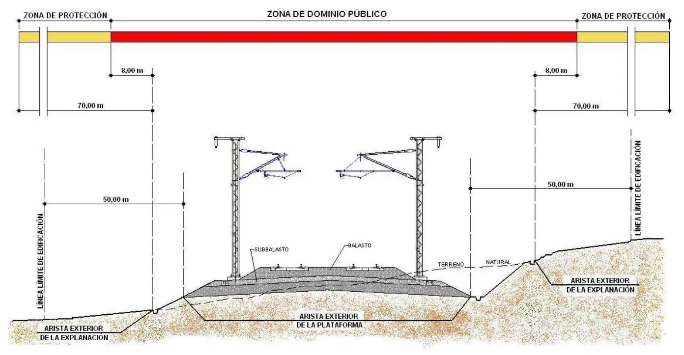
In order to effectively materialize the defense of the railway domain, the LOTT and RLOTT regulations establish a comprehensive system of territorial protection through the configuration of three differentiated safety bands, which extend symmetrically to both sides of the formation, as illustrated in the following figure:
I.2. PUBLIC DOMAIN ZONE
The Public Domain Zone is configured as the territorial space comprising the formation itself plus a perimeter strip of eight meters in width that projects linearly on both sides of the latter. Within the limits of the Public Domain Zone, the carrying out of any type of commercial activity, construction of civil works, or installation of infrastructures of diverse nature is expressly prohibited. However, those structures whose specific purpose is the protection and preservation of the railway network itself and its constituent elements are excepted from this general prohibition.
I.3. Legal Protection of the Formation
The regulatory framework for the protection of the railway formation is supported by two normative instruments of national character:
-
LAW 16/1987, of July 30, ON LAND TRANSPORT MANAGEMENT. (BOE, number 182, of July 31, 1988): This legislative text establishes the fundamental principles governing the organization and operation of land transport modes in Spanish territory, including specific provisions relating to the protection of the railway domain.
-
ROYAL DECREE 1211/1990, of September 28, REGULATION OF THE LAND TRANSPORT MANAGEMENT LAW. (BOE, number 241, of Oct. 8, 1990): This regulatory instrument develops in detail the principles contained in the management law, providing technical and procedural specifications for their practical application in the management of railway space.
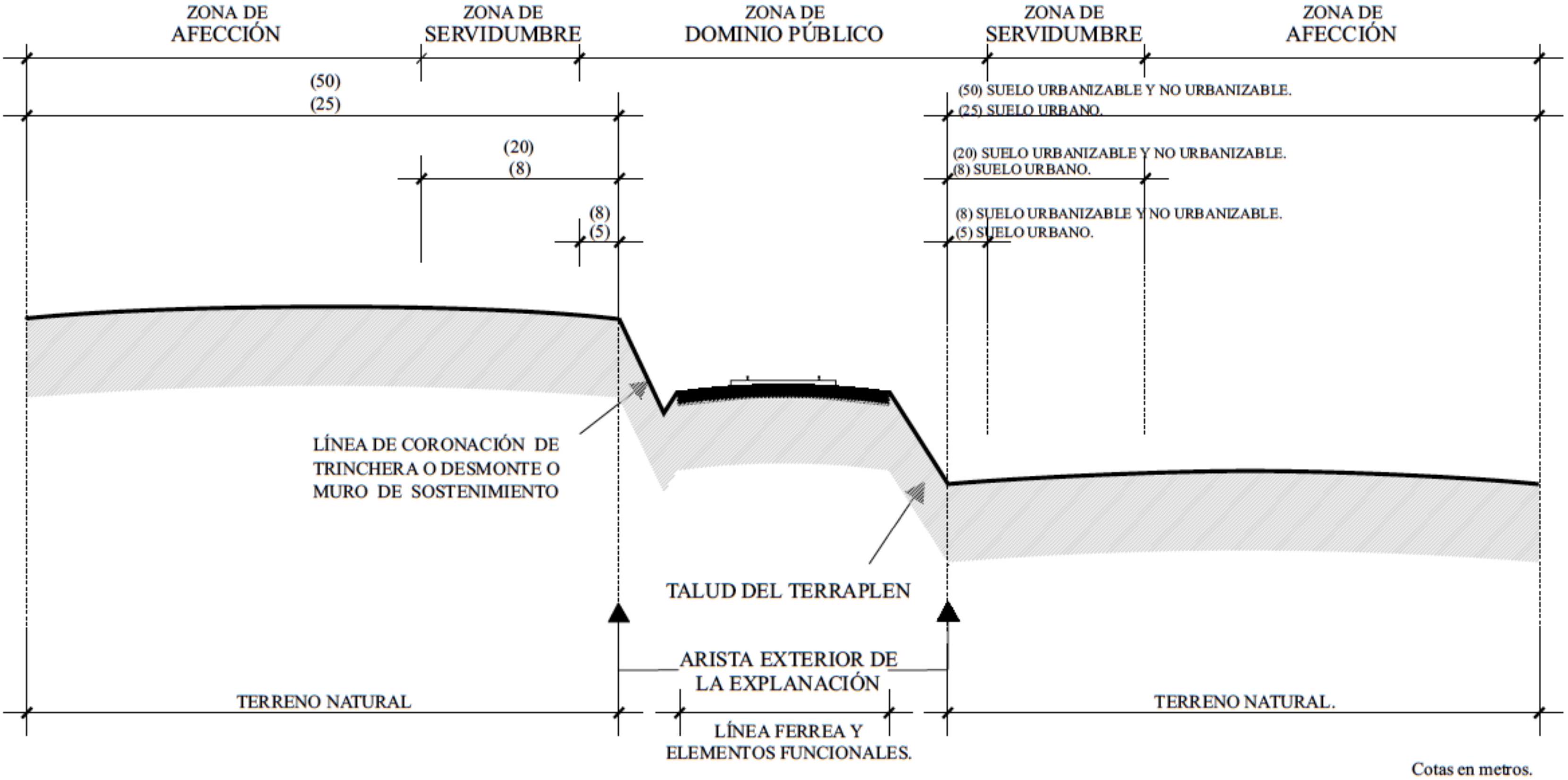
Within these regulations, precise definitions of the constituent elements of the railway domain are established: The FORMATION (EXPLANACIÓN) is defined as that strip of land on which the natural topography of the ground has been modified and which serves as the base for the construction of the railway line, the arrangement of its functional elements, and the location of its complementary facilities. The OUTER EDGE OF THE FORMATION (ARISTA EXTERIOR), on the other hand, represents the imaginary line that marks the intersection between the toe of the embankment slope, or alternatively the crown line of a cutting or excavation, or where appropriate, the retaining walls with the surrounding natural ground.
I.3.1. SERVITUDE ZONE (EASEMENT ZONE)
The Servitude Zone is configured as a territorial area divided into two parallel strips, located on both sides of the railway line. These strips present an inner limit marked by the Public Domain Zone and extend outwards until reaching two imaginary lines running parallel to the outer edges of the formation, situated at a distance of twenty meters from said edges. Within the limits of this zone, activities wishing to be carried out require express authorization from the railway operating company, and can only be carried out in cases where such execution does not imply a cession or transfer of fundamental railway rights.
I.3.2. AFFECTION ZONE (VICINITY ZONE)
The Affection Zone constitutes a complementary territorial area formed by two additional lateral bands, whose outer limit is marked by lines parallel to the perimeter edge of the formation, distanced fifty meters from these edges. In the event that it is intended to develop work, execute civil works, or other activities within this affection zone, it is imperative to obtain prior authorization from the Railway Company responsible for the operation of the line. An important differentiating characteristic is that the level of regulatory and administrative requirement that the state administration and even the railway companies themselves exercise in this Affection Zone results considerably less compared to the restrictions and controls applicable in the Servitude Zone, thus allowing a more flexible regime in the management of activities in this territorial space.
I.4. Dimensions of the Formation
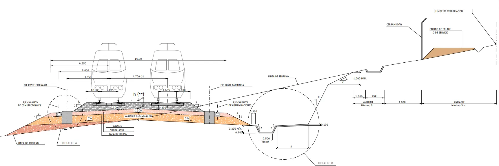
For a comprehensive understanding of railway infrastructure and its spatial requirements, it is essential to analyze in detail the different dimensions that make up the formation. Below is a scheme breaking down each of these components:
 Dimensions of the formation. Schema. NAP 1-2-1.0 Railway layout design
Within this configuration, the different dimensional parameters are defined according to the following technical criteria:
- a: Track gauge in Renfe = 1,668 mm (Iberian gauge)
- b: Electrification foundation = from 1 to 2 m (support infrastructure for electrified lines)
- c: Ditch width (lateral drainage) = from 0.5 to 1 m (for surface water evacuation)
- d: Ballast slope spread (Derrame) = ranges from 0.5 to 1 m, depending on the height of the ballast bed (natural slope of the ballast material)
- e: Track spacing (Entrevia - separation between rails) = from 2.1 to 3 m, according to specific operational needs
- h: Ballast shoulder = from 0.8 to 1 m, dimensioned according to lateral stability needs
- n: Electrification gauge = minimum distance between the active face of the rail and the posts = 2.1 m (critical safety parameter)
- p: Walkways (lateral circulation spaces) = can be one or two corridors of 0.7 to 1 m wide each
Looking closely at this schematic representation, we can verify that a properly configured formation, measured between ditches, must reach dimensions ranging between 12.70 meters and 17.40 meters for a double electrified track configuration, considering a single lateral walkway and not yet incorporating the additional requirements of railway signaling, nor stabilization slopes, nor complementary sanitation and drainage systems.
In contemporary railway construction practice, a fundamental technical principle is recognized: Traditionally, it has been considered that the territorial space demanded by the railway to develop its logistical function is significantly smaller compared to the spatial requirements of other competitive modes of transport. However, when this premise has been taken to the extreme, it has frequently generated the construction of railway lines on strips of insufficient land, which has compromised the ability to carry out railway operations with the slack and efficiency demanded by modern traffic. For a better visualization and understanding of the spatial distribution of all railway facilities, the previous figure schematically and approximately dimensions the set of elements that make up the railway infrastructure, thus allowing a clearer assimilation of everything exposed in this section.
Chapter II Subgrade
The subgrade constitutes the deepest stratum of the track infrastructure, functioning as the structural element responsible for absorbing, distributing, and definitively resisting all mechanical forces generated by the dynamics of train circulation, as well as by the self-weight of the track superstructure resting on it.
From a constructive classification perspective, it is possible to categorize the subgrade according to its nature and formation process into three fundamental typologies:
- Natural subgrades: Those that take advantage of the existing terrain with a minimum of intervention or surface preparation.
- Prepared subgrades: Those resulting from conditioning, improvement, and treatment works of the natural soil through stabilization, compaction, and geotechnical reinforcement techniques.
- Artificial subgrades: Those constituted on masonry works and specifically designed engineering structures, such as piles, tie beams, and deep foundation systems.
These three categories represent different levels of constructive complexity and respond to different geotechnical and topographic conditions of the terrain in question.
II.1. Missions of the Subgrade
Load capacity and mechanical resistance sufficient to support both static forces originating from the self-weight of the superstructure and its content, as well as dynamic forces derived from train circulation, with their corresponding impulsive and vibratory loads.
Additionally, the subgrade must fulfill a fundamental hydraulic function: efficiently evacuate the waters that would otherwise infiltrate and remain in prolonged contact with the ballast bed and the subgrade itself, causing significant damage. The presence of water in the subgrade structure generates multiple detrimental effects that compromise its durability and functionality:
- Clay expansion: The presence of water causes uncontrolled volumetric expansion of clay materials, simultaneously contaminating ballast layers with fines that close the interstices.
- Micro-cracking effect: Accumulated water undergoes freezing and thawing cycles, progressively disintegrating the subgrade material through the cycloidal action of ice.
- Embankment collapse: In embankment and side-hill configurations, water infiltration can completely interrupt the continuity of the subgrade, generating catastrophic subsidence and track cuts that paralyze railway operation.
II.2. The Subgrade in Old Lines
The constructive heritage of contemporary railway lines presents a significant challenge requiring historical understanding. Railway engineers of the mid-nineteenth century (the construction period of practically all current lines of the Spanish network) were content with designing and executing subgrades according to the minimum requirements imposed by the longitudinal leveling of the tracks, without considering other fundamental parameters.
Consequently, they carried out the necessary cuts and embankments solely to achieve the desired altimetric grade, without directing specific attention to the geotechnical quality of the ground or its bearing capacity under dynamic loads. This simplistic constructive approach allowed subgrades executed in eras where railway operation parameters were radically different to be inherited: axle loads were very reduced, train circulation speeds were notably lower, and traffic intensities remained at fractions of contemporary values.
In the current context, operational reality has changed drastically. Now, with axle loads reaching 22 tons, maximum speeds close to 200 km/h on high-speed lines, and traffic intensities ranging between 100,000 and 200,000 tons daily, these old subgrades present very numerous structural problems of technically uncertain solution. The required repairs and reinforcements constitute complex civil works, costly and difficult to execute, particularly because they must be carried out without suppressing traffic of circulating trains and respecting the primitive design grades of the track, which significantly restricts available constructive options.
II.2.1. Problems in Old Subgrades
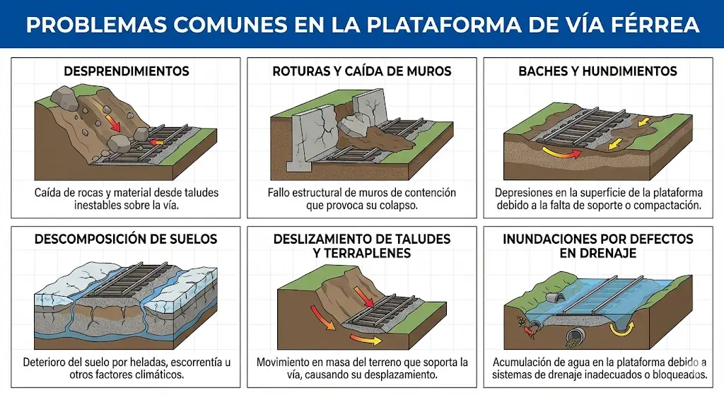
In the graphical representation presented below, the most recurrent pathologies and problems manifesting in railway subgrades of considerable antiquity are illustrated. These problems constitute concrete manifestations of deterioration processes derived from changes in the operational parameters mentioned above.
II.2.2. Solutions to Old Subgrade Problems
To face the diversity of pathologies affecting these old subgrades, specific engineering strategies adapted to each type of identified problem have been developed and applied. The technical procedures usually employed are detailed below:
A. Landslides in cuts: These problems require a multifaceted approach including:
- Execution of massive excavations to eliminate unstable material.
- Exhaustive cleaning of the slope to remove loose stones and weathered material.
- Construction of cladding walls for containment.
- Covering with protection nets and geogrids.
- Placement of specialized rock-catch fencing.
- Execution of riprap or retaining walls of greater magnitude.
- In extreme cases, construction of artificial tunnels to cover the zone.
B. Breakage and fall of walls: Facing structural failures of existing walls, the following are applied:
- Complete demolition of the damaged wall and construction of a new one.
- Massive excavations of adjacent land to relieve loads on the wall.
C. Flooding and drainage problems: Water management requires continuous interventions:
- Periodic cleaning of the sanitation system to maintain permeability.
- Widening and deepening of lateral ditches for greater capacity.
- Multiplication of transverse drainage points and sections.
D and E. Clay pockets and soil decomposition: To restore bearing capacity, the following are implemented:
- Installation of drainage systems (drains) under the subgrade and on its sides.
- Soil improvements through multiple techniques: removal of incompetent material, contribution of graded aggregates, placement of geotextiles, supply of sands, stabilization with lime, cement injections, etc.
- Improvement and integral redesign of ditches.
- Lowering of lateral walkways and establishment of specific systems for elimination of accumulated water.
F. Cutting and sinking of embankments: The solution to these critical problems requires:
- Construction of riprap at the toe of the embankment with filling of the sunken zone.
- Alternative implementation of walls at the toe of the embankment.
- Assembly of rail barriers using pile driving techniques.
- Sanitation systems through longitudinal or transverse drainage screens.
- Complete recomposition of the embankment through contribution of improved aggregates and elimination of primitive soils.
II.3. New Construction Subgrades
In the process of design and specification of the most appropriate subgrade for a new railway line, it is essential to collect and analyze a set of fundamental technical data that will determine the characteristics of the constructive solution:
- Geotechnical quality of existing natural soil: Determination through stratigraphic studies of bearing capacity and compressibility characteristics of the ground.
- Technical category of the line to be built: Function of the maximum planned operating speed and the expected volume of traffic.
- Desired bearing capacity: The target CBR (California Bearing Ratio) index value for the finished subgrade.
1. Determination of soil quality:
Soils are classified into four distinct categories according to the specifications of the International Union of Railways (UIC):
- QS0: Very difficult to improve soils (organic materials, soils with soluble substances, highly expansive clays, etc.).
- QS1: Bad soils (containing between 40% and 15% fine particles, highlyerodible rocks, marls with low bearing index, etc.).
- QS2: Medium soils (containing less than 15% fine particles and rocks of medium hardness).
- QS3: Good soils (containing less than 5% fine particles and rocks of hard and resistant characteristics).
This classification system requires a previously exhaustive geotechnical study to categorize the existing soil into one of the four divisions mentioned.
2. Choice of line category:
Railway lines are classified into categories according to the volume of traffic they support and the maximum operational speed developed on them. In the Spanish railway administration ADIF, lines have been classified into seven different categories:
| CATEGORY | FICTITIOUS DAILY TRAFFIC | |
|---|---|---|
| 1 | A | \(85.000 \geq \mathrm{Tf} \geq 50.000\) |
| B | \(50.000>\mathrm{Tf} \geq 28.000\) | |
| C | \(28.000>\mathrm{Tf} \geq 14.000\) | |
| 2 | \(14.000>\mathrm{Tf} \geq 7.000\) | |
| 3 | A | \(7.000>\mathrm{Tf} \geq 3.500\) |
| B | \(3.500>\mathrm{Tf} \geq 1.500\) | |
| 4 | \(1.500 \geq \mathrm{Tf}\) |
The calculation of fictitious daily traffic is performed using the following standardized expression:
\[T_{f}=\left(T_{v}+T_{m} \cdot K_{m}+T_{t} \cdot K_{t}\right) \cdot S\]Where parameters are defined according to:
- \(\mathrm{T}_{v}\) = Annual volume of passenger traffic expressed in equivalent tons
- \(\mathrm{T}_{\mathrm{m}}\) = Annual volume of freight traffic in tons
- \(\mathrm{T}_{\mathrm{t}}\) = Annual volume of traction locomotives traffic in tons
- \(\mathrm{K}_{\mathrm{m}}\) = Enhancement coefficient for freight traffic characteristics. Its standard value is 1.15; except for tracks supporting preponderant traffic of 20-ton axles, where it adopts the value of 1.30
- \(\mathrm{K}_{\mathrm{t}}\) = Enhancement coefficient for circulation of traction locomotives (fixed factor of 1.40)
- \(\mathrm{S}\) = Dimensionless track quality coefficient varying from 1.00 to 1.25, determined according to:
- \(S=1,00\) for lines without passenger traffic or with essentially local traffic
- \(S=1,10\) for lines whose passenger traffic uses trains with maximum speed \(\leq 120 \mathrm{Km} / \mathrm{h}\)
- \(S=1,20\) for lines whose passenger traffic uses trains with speeds included in the range \(120<v \leq 140 \mathrm{Km} / \mathrm{h}\)
- \(S=1,25\) for lines whose passenger traffic uses trains with maximum speed \(>140 \mathrm{Km} / \mathrm{h}\)
3. Choice of bearing capacity:
According to the bearing capacity desired in the treated soil, the different subgrade options are classified into three differentiated groups:
- P1: Bad subgrades, with CBR index \(<5\) (limited bearing capacity)
- P2: Medium subgrades, with CBR index comprised between \(5<\mathrm{CBR}<20\) (moderate bearing capacity)
- P3: Good subgrades, with CBR index \(>20\) (excellent bearing capacity)
The decision matrix presented below develops the design process to obtain the desired subgrade (P1, P2, or P3) through the construction of the capping layer (upper stratum of the subgrade) from untreated or previously improved soil (categories QS0, QS1, QS2, or QS3).
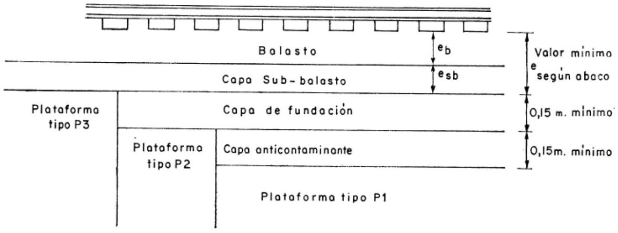
II.4. Formation (Capping) Layer Thickness (UIC 719 R)
The dimensioning of the capping layer forming the upper stratum of the subgrade requires consulting standardized design matrices relating initial soil quality to thickness and characteristics of materials to be used. The following UIC 719 R table specifies minimum thicknesses required to obtain different levels of bearing capacity:
BEARING CAPACITY OF A SUBGRADE
| Support Soil Quality | Capping layer to constitute to obtain a subgrade with determined bearing capacity | Bearing capacity obtained in the subgrade | |
|---|---|---|---|
| Soil Quality | Minimum Thickness in m | ||
| QS1 | QS1 | - | P1 |
| QS2 | 0.50 | P2 | |
| QS3 | 0.35 | P2 | |
| QS3 | 0.50 | P3 | |
| QS2 | QS2 | - | P2 |
| QS3 | 0.35 | P3 | |
| QS3 | QS3 | - | P3 |
This table should be interpreted as follows: If existing natural soil belongs to category QS1 (bad) and it is desired to obtain a class P3 subgrade (good), it is necessary to construct a capping layer with QS3 quality material with a minimum thickness of 50 centimeters.
II.5. Formation (Capping) Layer Thickness (NRV 3-4-1.0)
The current Spanish regulation established by the railway administration (Renfe-Track Norm NRV 3-4-1.0) provides complementary specifications for dimensioning the capping layer, with technical criteria that may result more demanding than UIC standards in some cases:
N.R.V. 3-4-1.0 - CAPPING LAYER THICKNESS ACCORDING TO SOIL QUALITY AND REQUIRED LOAD CLASS
| SUPPORT SOIL QUALITY | CAPPING LAYER TO OBTAIN THE SUBGRADE LOAD CAPACITY CLASS, MARKED BY THIS TABLE | SUBGRADE LOAD CAPACITY CLASS | |
|---|---|---|---|
| SOIL QUALITY | MINIMUM THICKNESS IN METERS | ||
| Q S1 | Q SI | - | P. 1 |
| FINE SOIL TREATED WITH BINDERS | 0.30 | P. 2 | |
| Q S2 | 0.55 | P. 2 | |
| Q S3 | 0.40 | P. 2 | |
| Q S3 | 0.60 | P. 3 | |
| Q S2 | Q S2 | - | P. 2 |
| Q S3 | 0.40 | Pi 3 | |
| Q S 3 | Q S3 | - | P. 3 |
Where bearing capacity classifications are defined as:
- P. 1 : \(\mathrm{CBR} \leq 5\) (Low bearing capacity subgrade)
- P. 2 : \(5<C B R \leq 20\) (Medium bearing capacity subgrade)
- P. 3 : \(20<C B R\) (High bearing capacity subgrade)
Observing both norms, it is appreciated that the Spanish NRV specification introduces the concept of “fine soil treated with binders” as an economizing alternative for thickness when working with deficient soils, allowing thickness reduction through stabilization with cement or lime.
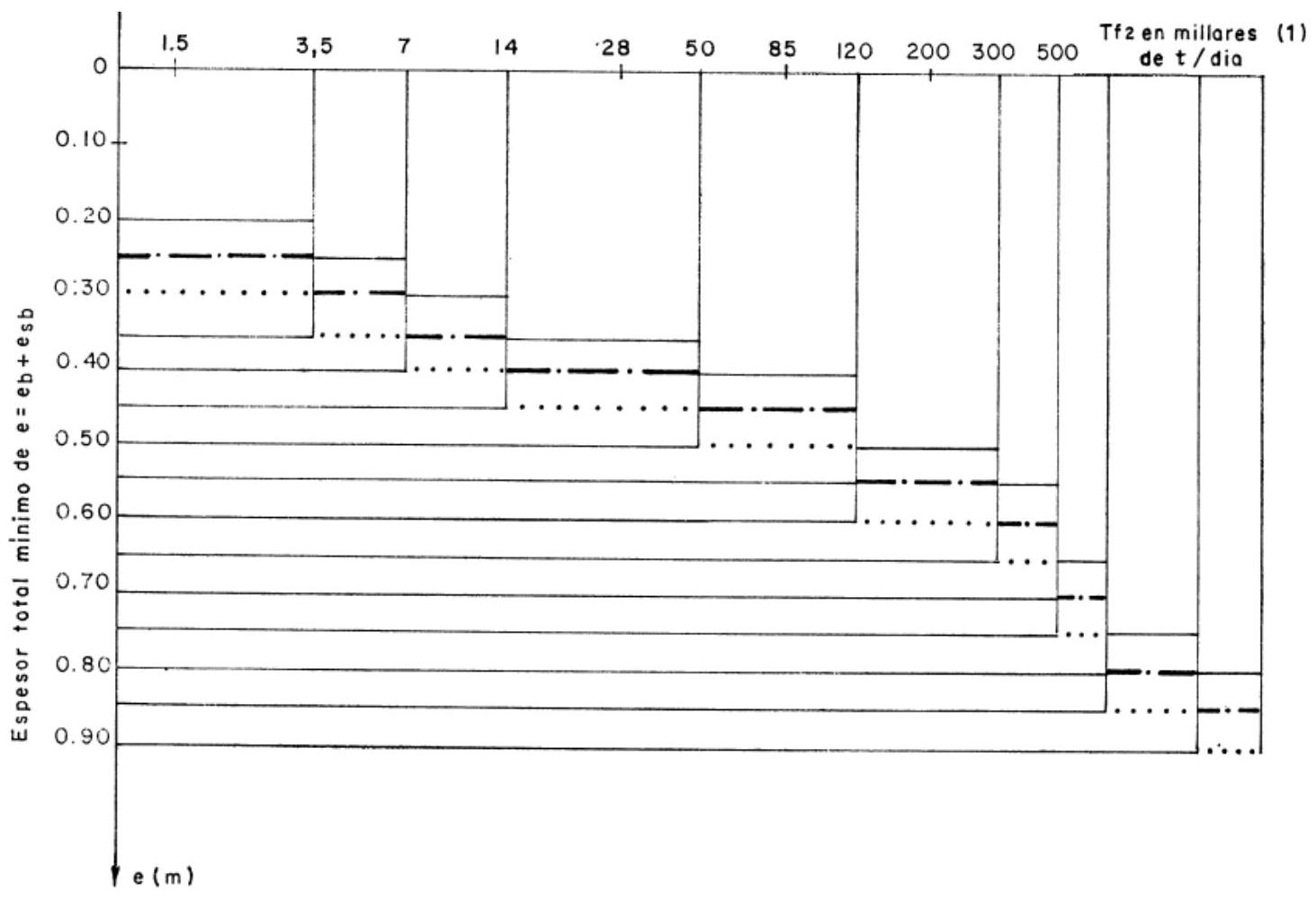
II.6. Ballast Layer Thickness
The determination of the optimal thickness that the ballast layer must present constitutes a central issue in the structural design of the railway track. There are numerous scientific and technical studies developed over decades addressing the quantification of the appropriate thickness for the ballast layer or for the combined set of ballast plus sub-ballast when the latter is positioned directly under the sleepers. Notably, quantitative results obtained through rigorous theoretical investigations coincide substantially with empirical criteria that accumulated experience has sedimented over the years.
The ballast layer thickness is primarily determined by operational parameters: the total number of trains circulating daily, the maximum load transported by each vehicle axle, and the operating speed of compositions, all of which are synthesized in the concept of line category (recalling that this category is determined through the concept of fictitious daily traffic Tf calculated previously).
Additionally, the required thickness depends on soil quality or more precisely on the quality achieved after subgrade formation. However, once the P3 type (excellent bearing capacity) subgrade configuration has been reached, ballast thickness will depend mainly on the line category, in accordance with the following standardized values:
- Group 1A (maximum traffic and speed): \(e=45\) centimeters
- Group 1B: \(e=40\) centimeters
- Group 1C: \(e=40\) centimeters
- Group 2: \(e=35\) centimeters
- Group 3A: \(e=30\) centimeters
- Group 3B: \(e=25\) centimeters
- Group 4 (minimum traffic and speed): \(e=25\) centimeters
The value of ballast and sub-ballast layer thicknesses is established respecting the following fundamental technical restrictions:
- The minimum thickness of the sub-ballast layer must be at least half of the total thickness e indicated in the chart. When ballast thickness must be greater than half of e, sub-ballast thickness will be proportionally increased by the same amount.
- In high-speed railway lines (exceeding 200 km/h), total thickness e must not descend below 60 centimeters in normal circumstances, although exceptionally the value of 50 centimeters may be adopted in justified cases.
- Capping layer thickness must correspond to values specified in previous tables.
- Depending on technical subgrade quality achieved, specific seating layers indicated in ADIF Standard 2-1-0.1 must be arranged.
To determine these optimal thicknesses in existing track renewals, it is imperative to previously know the bearing capacity of the current subgrade and improve it when technically feasible, as better results are obtained by improving this bearing capacity than simply providing greater thickness in the ballast layer.
Legend:
- WOODEN SLEEPER
- CONCRETE SLEEPER OF LENGTH \(\ell \geq 2,40 \mathrm{~m}\)
- CONCRETE SLEEPER OF \(2,20 \leq \ell<2,40 \mathrm{~m}\)
(1) \(T_{f_{2}}=\) Daily Fictitious Traffic NRV 3-4-1.0 for ballast thickness calculation
II.7. Ballast Bed Sections
To ensure the railway track optimally develops its functions and maintains service durability, it is necessary to adequately dimension all layers constituting the ballast bed based on operational parameters of each line. N.R.V. 3-4-1.0 regulation provides detailed specifications for seating layer thicknesses:
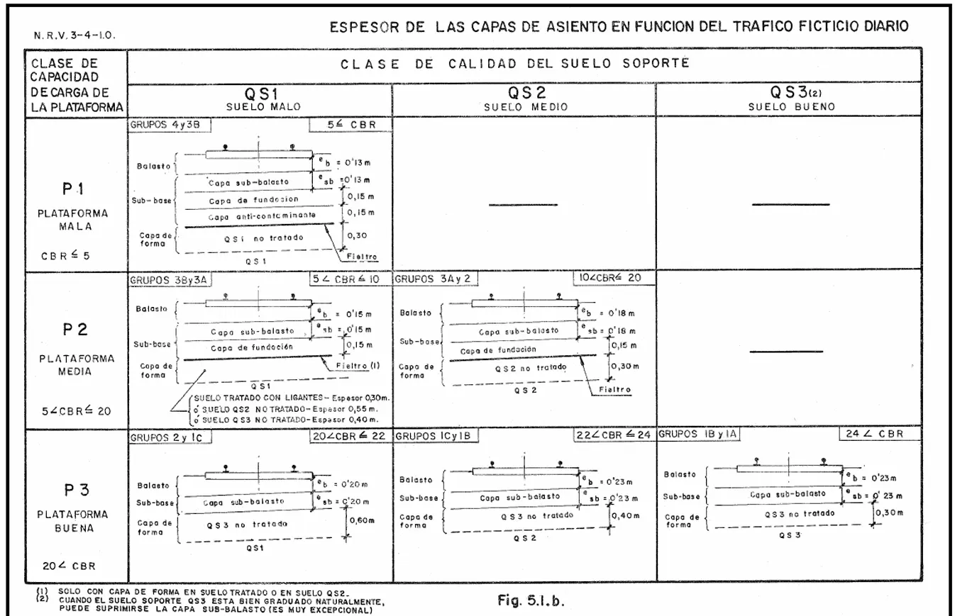 This matrix allows determining, based on load capacity class achieved in the subgrade and support soil quality, which railway category groups are compatible with each combination.
Chapter III The Ballast Bed (Banqueta)
The ballast bed constitutes the layer of granular material that forms the immediate support surface on which the entire structural framework of the track (the set formed by sleepers, rails, and fastening systems joining both elements) is arranged. This layer is typically composed of selected aggregates that envelop the sleepers and keep them embedded, with component materials varying according to regional availability: sands, improved soils, gravel, ballast of distinct characteristics, slag from crushed steel industries, and other aggregates compatible with technical requirements.
Geometrically, the cross-section of the ballast bed presents a characteristic trapezoidal shape, with the larger base resting on the subgrade and specific dimensions described in subsequent figures (in this context referring specifically to beds constituted by ballast). The capacity of the ballast bed to maintain sleepers in their relative position is achieved primarily through internal friction generated between constituent aggregates, complemented by friction produced between sleepers and these same materials.
The ballast bed must fulfill a series of critical functional missions for safe and efficient operation:
- Bracing and stability: Keep sleepers properly braced and by extension rails fastened to them, preventing unwanted longitudinal movements and transverse movements compromising track gauge, constantly maintaining longitudinal leveling and horizontal alignment of the track.
- Impact damping: Damp and dissipate dynamic actions of trains on the track assembly, reducing transmission of impulsive loads.
- Load distribution: Distribute vertical loads applied by sleepers onto the subgrade gradually and homogeneously.
- Drainage and water evacuation: Facilitate water passage through the aggregate matrix so it is efficiently evacuated from the subgrade, thus avoiding formation of puddles and potholes that could undo the ballast bed structure.
- Subgrade protection: Protect the subgrade from frost effects and decomposition of its upper capping layer.
- Geometry maintenance: Allow, through simple and economically viable maintenance works, recovery of track alignment and leveling when these characteristics degrade due to use (tampable beds with vibro-tampers).
- Shape recovery: Allow the ballast bed to recover its initial geometry through simple profiling works so the track continues maintaining its technical characteristics throughout its utilization cycle (profilable beds).
Historically, early railways completely lacked a ballast bed, arranging sleepers directly on the formation or burying them in the ground. When serious leveling problems caused by insufficient soil bearing capacity were noted, it was decided to experiment with depositing layers of gravel or sand acting as load distributors and leveling facilitators.
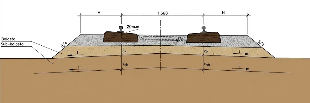
III.1. Ballast Bed Sections
Dimensioning and technical configuration of the ballast bed require clear identification of each of its constructive components. The following figure illustrates fundamental constituent elements:
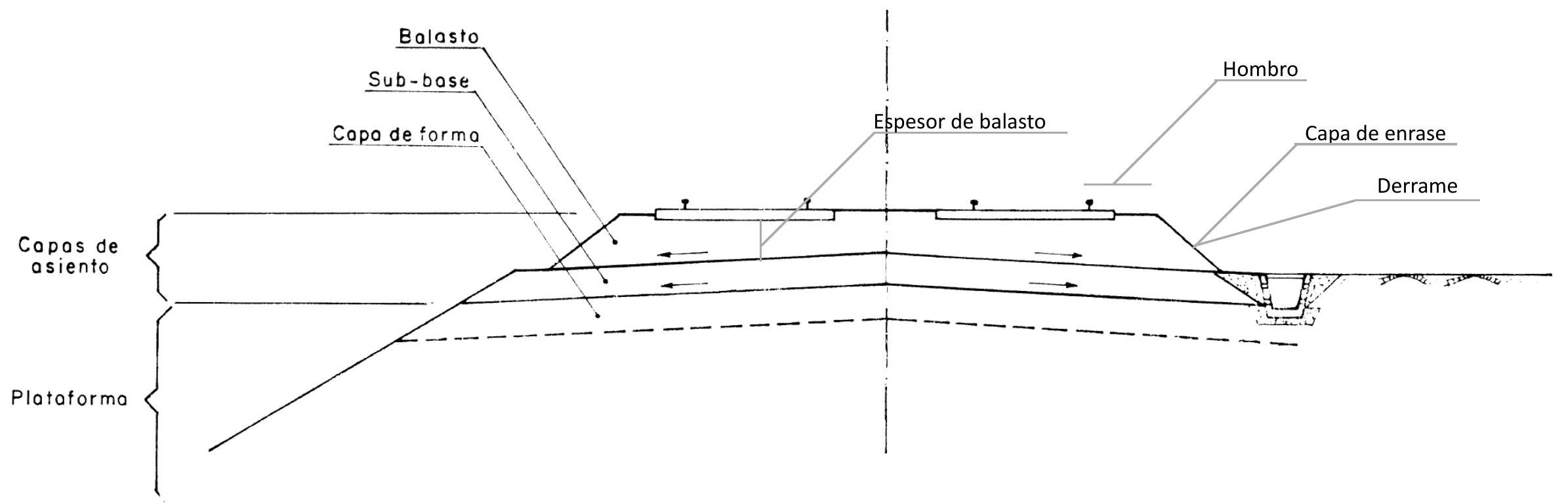
Each of these elements is technically defined according to:
- Top level layer (Capa de enrase): The upper surface defining the external profile of ballast volume constituting the bed, situated at specific depth under rail bottom level.
- Capping layer (Capa de forma): The subgrade termination stratum located immediately under the ballast bed, constituting the interface between ballast and improved or natural soil.
- Ballast shoulder (Hombro): The horizontal distance measured between upper edge of the ballast bed and nearest point of track rail (generally outer foot).
- Slope (Derrame): The inclined lateral surface of the ballast bed, determined by natural angle of repose of aggregate material constituting the bed (natural slope).
- Sur-ballast (Sobrebanqueta): An additional elevation of ballast material arranged specifically to reinforce and stabilize the lateral shoulder of the bed.
- Ballast thickness: Vertical dimension measured from bottom face of sleeper to capping layer, assuming entire bed is constituted by ballast without intermediate layers.
According to technical specifications required by railway administration ADIF, standard dimensions for ballast beds have been established according to line category:
Ballast bed dimensions required by ADIF (Single Track)
| Dimensions | Groups.1AyIB | Groups.IBylC | Groups.ICy 2 | Groups 2y 3 A | Groups 3 Ay 3 B | Groups 3 By 4 |
|---|---|---|---|---|---|---|
| Thicknesses: \(\mathrm{e}_{\mathrm{b}}=\mathrm{e}_{\mathrm{sb}}\) | 23 cm | 23 cm | 20 cm | 18 cm | 15 cm | 13 cm |
| Top level layer | Surface: 2 cm below lowest point of rail foot | |||||
| Shoulder: H | 105 cm | 105 cm | 100 cm | 100 cm | 95 cm | 90 cm |
| Transverse slope: i | 5\% | 5\% | 5\% | 3\% | 3\% | 3\% |
DOUBLE TRACK
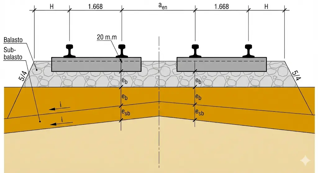
| Dimensions | Groups IAyIB | Groups IBylC | Groups ICy 2 | Groups 2 y 3 A | Groups 3Ay3B | Groups 3 By 4 |
|---|---|---|---|---|---|---|
| Thickness: \(\mathrm{e}_{\mathrm{b}}=\mathrm{e}_{\mathrm{sb}}\) | 23 cm | 23 cm | 20 cm | 18 cm | 15 cm | 13 cm |
| Top level layer | Surface: 2 cm below lowest point of rail foot. | |||||
| Shoulder: H | 105 cm | 105 cm | 100 cm | 100 cm | 95 cm | 90 cm |
| Inter-track width: gen | 234 cm | 234 cm | 230 cm | \(\mathbf{2 3 0 ~ c m}\) | \(\mathbf{2 2 0 ~ c m}\) | 210 cm |
| Transverse slope: i | 5\% | 5\% | 5\% | 3\% | 3\% | 3\% |
These technical specifications ensure that regardless of line category, ballast beds provide adequate bracing, maintaining coherence with established drainage and stability requirements.
Chapter IV Ballast
Ballast constitutes a specifically prepared and selected aggregate, whose base composition is crushed stone or rock classified through screening according to standardized technical specifications developed by each railway administration for application in railway works. generally, modern ballast consists of clean, controlled granulometry gravel, whose component elements present an average size comprised between 30 and 60 millimeters equivalent diameter.
According to standardized specifications, certain granulometry limits must be mandatorily respected. The percentage of elements with dimensions comprised between 25 and 16 millimeters, determined through standardized sieving tests, must not exceed 27 percent by weight relative to total analyzed sample. Similarly, percentage of elements with dimensions inferior to 16 millimeters must not exceed 5 percent by weight relative to total sample, as specified in annex B of standard UNE 146147.
In modern railway track configurations, ballast constitutes base material for construction of ballast beds, so there must exist clear and functional technological correlation between requirements established for ballast beds and technical characteristics of ballast chosen for their formation.
IV.1. Shape of Ballast
Shape of ballast constituent elements (individual stones) is a critical aspect of bed performance. These elements must possess sharp and pronounced edges, a fundamental characteristic that, once bed has reached its operational consolidation state after repeated train passage, favors maximum internal friction between particles, significantly improving longitudinal and transverse stability of entire track.
More specifically, ballast elements must present a polyhedral geometric shape (approximately cubic), with multiple faces and edges. Conversely, ballast with flat (slab-like) or acicular (elongated and needle-like) shapes must be completely avoided. These deficiently shaped elements present undesirable mechanical behavior: acicular and slab-like elements tend to break under cyclic operation loads, irreversibly altering aggregate original granulometry and creating plastic zones within bed that compromise its bearing and bracing function.
IV.2. Petrographic Study
Adequate technical characterization of ballast requires integral geological analysis of material, complemented with specific petrographic investigations. Geological-geotechnical study carried out in extraction quarry must be mandatorily accompanied by detailed petrographic analysis of representative samples of material from that quarry, with specific purpose of effecting petrological (mineralogical) classification of parent rock and evaluating possible alterations experienced by component minerals.
This petrographic study also reveals fundamental characteristics determining significantly physical, chemical, and mechanical behavior of rock under operational service conditions.
Petrographic analysis must consist of two differentiated parts:
- Macroscopic description: Detailed visual evaluation of rock according to guidelines contained in standard UNE-EN 932-3, recording characteristics such as color, apparent texture, discontinuities, signs of weathering, etc.
- Microscopic description: Study through petrographic microscope of polished thin sections of rock, allowing identification of specific mineral composition, crystalline textures, existence of intergranular fractures, and evidences of alteration.
Complementarily, when technically deemed necessary due to finding evidences of complex or ambiguous mineralogy, X-ray diffraction analysis will be carried out, providing unequivocal identification of crystalline phases present.
IV.3. Homogeneity
The homogeneity test constitutes an essential quality control executed when, during initial ballast sampling process for characterization tests, evident presence of particles evidencing weathering or soft components is observed in proportion visually estimated superior to 5% of total examined sample.
In cases where heterogeneity is detected, it is necessary to proceed to collection of multiple samples, in sufficient quantity so that, after their sieving employing standardized sieves with openings of 50 mm, 40 mm and 31.5 mm, minimum mass of 100 kg of material retained on 31.5 mm sieve is obtained, complemented with other 100 kg additional retained on 40 mm sieve.
From each of these granulometric fractions, careful visual selection of stones presenting greatest evidence of weathering or softness proceeds, selecting material until reaching exactly 5% of each fraction (5 kg ± 50 g). This selected mass is consolidated into unique 10 kg sample submitted to Los Angeles abrasion test, procedure described in detail in subsequent sections. If Los Angeles abrasion coefficient obtained complies with limit values established for ballast, homogeneity is considered satisfactory and ballast results suitable for use. Otherwise, ballast will be rejected as unacceptable.
Alternatively, simplified methodology consisting of direct manual extraction of visibly weathered or soft fragments from minimal 40 kg mass dry test sample can be opted for. In this alternative procedure, ballast is considered to present adequate homogeneity when total mass of weathered or soft fragments does not exceed 5% of total mass of 40 kg sample.
In this alternative procedure, additional complementary sample of 15 kg of altered material proceeding from same lot as 40 kg sample must also be collected, in case it results necessary in later phases to effect Los Angeles abrasion test on this complementary sample for validation.
IV.4. Hardness and Resistance of Ballast
Presence of sharp and pronounced edges in ballast elements also confers fundamental elasticity characteristic: elements couple and interlock with each other upon repeated train passage, allowing microstructural redistributions maintaining bed dimensional stability. For this elasticity to be maintained during track long operational life period, it is imperative that ballast elements possess ample specific compressive hardness, as well as very elevated resistance to abrasive wear and impact breakage.
Simultaneously, routine maintenance and track modernization operations employ specialized heavy machinery (vibro-tamping batteries, etc.) subjecting ballast to intensive impact and friction cycles. This operational reality demands ballast stones possess extraordinarily high wear resistance, both by abrasion and brittle fracture, to avoid rapid creation of fines compromising bed functionality.
IV.5. Cleanliness of Ballast
A critical characteristic of quality ballast is that it must be practically free of fine particles (dust and sand) that would otherwise progressively obstruct interstitial spaces remaining between larger ballast elements, phenomenon known as clogging. When these pores are blocked with fines, bed drainage capacity is fundamentally compromised, creating plastic behavior zones where water accumulates, generating previously described problems.
Complementarily, generation of new fines during bed operation must be completely avoided, situation occurring if ballast stones suffered significant mechanical degradation by brittleness. If base rock is of weak nature or has scarce impact resistance, cyclic shock between stones upon train passage would cause fragmentation, generating dust filling empty spaces. This consequence (internal fines generation) would result as harmful as initial contamination, reason for which wear resistance is absolutely critical parameter in ballast specification.
IV.6. Nature of Ballast
Selection of parent rock from which ballast will be extracted constitutes critical engineering decision. Rocks whose material is employed for ballast must present significant mineral homogeneity characteristics and cannot have inherent ease to disintegrate under action of time, weathering, or humidity and temperature cycles. For these fundamental reasons, sandstones, shales, or other similar sedimentary rocks inherently weak are not employed.
Neither acceptable are rocks presenting susceptibility to chemical oxidation processes or vulnerable to chemical attack by pure water or by ions dissolved in water (carbonates, sulfates, etc.), situations that would progressively degrade mechanical resistance under service climatic conditions.
Ballast destined for railway use must proceed specifically from mining extraction operations in quarry, followed by crushing (controlled fragmentation), screening (granulometric classification), and selection operations with or without complementary industrial treatment implying thermal modification (calcination, etc.).
Geological characteristics of ballast parent rock require it to possess siliceous nature (rich in silica) and preferably igneous origin (volcanic or plutonic) or metamorphic. Consequently, rocks of calcareous nature (calcium carbonate) or dolomitic (calcium and magnesium carbonate) will not be admitted, although these may be more economical to extract.
Ballast results unacceptable if containing fragments of wood, organic material, metals, plastics, easily alterable or weatherable rocks, thixotropic behavior materials, expansive or soluble substances, putrescible materials, combustible compounds, or any contaminant of industrial origin (wastes, polluting residues, etc.).
Due to high cost implied by extraction of high hardness siliceous rocks, in beds with less rigorous technical demands (secondary tracks, low traffic railways), employment of ballast proceeding from hard and resistant limestones is occasionally allowed, material designated as “second quality ballast” or “ballast B”. Those proceeding from siliceous or acidic rocks are classified as “type A ballasts”, being these of maximum requirement. To summarize this classification:
- Ballasts A: Acidic nature, siliceous composition (quality siliceous rocks)
- Ballasts B: Basic or alkaline nature, limestone composition (must be avoided as much as possible)
IV.7. Assessment of Ballast Characteristics
All railway administrations have established rigorous quality control and verification systems for technical characteristics of supplied ballast. These quality assurance protocols include:
Main characterization tests:
- Mechanical resistance tests
- Geometric shape analysis tests
- Granulometry tests (size distribution)
Sampling and control procedures: Samples are collected from following points in supply chain:
- From extraction quarries themselves (origin validation)
- From stockpiles where ballast is stored before utilization
- Even from wagons themselves transporting these stones in transit
In all cases results critical to indicate with precision origin and provenance of sampled material, to be able to trace any quality non-conformity to its source.
IV.8. Simple Compression Test
This experimental test allows evaluating and quantifying elasto-plastic behavior of each individual stone under axial load, information correlating directly with progressive degradation ballast will experience during its operational service life.
Test is effected subjecting standardized cylindrical specimen (dimensions: 10 cm height and 5 cm outer diameter) to compressive axial load applied uniformly on its two parallel flat faces. Load is increased gradually until reaching specimen brittle fracture point. Load per unit of cross-sectional area at exact moment of breakage constitutes resistance parameter sought to quantify.
Spanish railway administration ADIF specifies minimum resistance requirement: value must exceed 1,200 kiloponds per square centimeter (kp/cm²), corresponding approximately to 117.7 megapascals (MPa) in International System units.
IV.9. Resistance of Stone to Impact and Wear
Ballast wear process, provoked both by repeated impact and abrasion, exerts two differentiated detrimental effects on bed functional characteristics resulting equally harmful:
- Dust generation: Production of fine particles (dust) derived from wear tends to fill interstices remaining between larger stones, obstructing free circulation and drainage of water. This obstruction generates humid zones within bed behaving as deformable plastic beds, compromising bracing and leveling function.
- Loss of edges: Progressive breakage and wear of stone sharp edges causes gradual loss of bed elasticity, decreasing microstructural accommodation capacity under cyclic loads.
In synthesis, greater intrinsic resistance of ballast rock to surface tearing and mechanical shock, longer period during which bed functional technical characteristics remain intact.
Tearing resistance test universally utilized is denominated Los Angeles test, procedure determining numerical parameter denominated C coefficient (Los Angeles coefficient), measuring quantitatively material tearing resistance characteristic.
This coefficient is defined as mass percentage of fine particles produced when standardized granulometry and mass stone sample is milled (fragmented by repeated impact) together with specific number of steel balls inside cylinder rotating around its revolution axis. Test variables (balls diameter and weight, cylinder dimensions, number of revolutions, rotation speed) are fixed standardized according to type and severity of required test.
Most frequently utilized test protocol in railway industry is that employing 10 kg of stone fragmented in two granulometric fractions (5 kg stone between 1” and 1½” diameter, and another 5 kg between 3/4” and 1”), inside cylinder of 508 mm length and 711 mm diameter, with twelve identical steel balls whose total mass sums 5 kg. Number of cylinder revolutions is 1,000, executed at angular speed comprised between 188 and 208 rad/s (equivalent to 30-33 revolutions per minute).
Specifically for application in railway ballast, maximum Los Angeles coefficient of 19% is demanded, limit ensuring sufficient tearing resistance for acceptable useful life.
IV.10. Granulometry Assessment
Ballast whose granulometric distribution is technically adequate must possess simultaneous capacity to fulfill two functions that, at first sight, seem contradictory:
- First function: Effectively hold and brace sleepers firmly, characteristic requiring presence of large dimension stones generating friction and interlocking. This requirement implies completely rejecting presence of small stones.
- Second function: Allow free movement of tampers (vibrating equipment) in mechanized track tamping operations, and achieve durable track leveling. This second characteristic requires presence of relatively small stones, but sufficiently large to resist without dismembering under intense vibration of tampers, as it is known very small stones crumble more easily.
Combining and balancing all these conflicting technical needs, particular and demanding granulometric distribution has been specified for ballast. This granulometry test is performed according to technical procedures contained in standard UNE-EN 933-1, utilizing dry sieving.
Sieve series to utilize is: 63 mm - 50 mm - 40 mm - 31.5 mm - 22.4 mm.
In each of these sieves variable quantity of stone must be retained which must match mandatorily within minimum and maximum percentages established by technical specification.
Graphic representation of these tolerances in Cartesian diagram where in abscissa axis sieve sizes are represented in logarithmic scale, and in ordinate axis accumulated percentages of passing material (retained) are represented, gives rise to denominated granulometric spindles, defining acceptable envelope for size distribution:
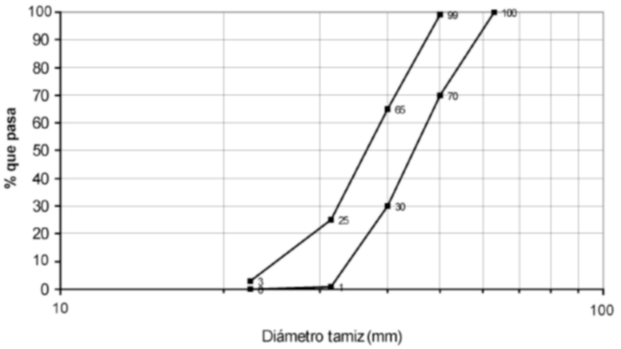 Granulometric Spindle ET 03.360.004.0 Adif Technical specification ballast
| Ballast granulometric curve | |
|---|---|
| Sieve size (mm) | \% passing (by weight) |
| 63 | 100 |
| 50 | 70-99 |
| 40 | 30-65 |
| 31.5 | 1-25 |
| 22.4 | 0-3 (for reception of lots situated in production center) |
| 0-5 (for reception of lots situated in work or intermediate stockpile) |
IV.11. Shape Tests
IV.11.1. ELEMENTS OF MINIMUM THICKNESS
This test is carried out according to procedures specified in annex B of standard UNE 146147, standard establishing methods to identify and quantify elements presenting excessive minimum dimensions.
Percentage of elements with dimensions comprised between 25 and 16 millimeters, determined through this standardized sieving analysis, must not exceed under any circumstance 27% in mass relative to total analyzed sample.
Simultaneously, percentage of elements whose maximum dimension is inferior to 16 mm determined through same procedure, must never exceed 5% in mass relative to total tested sample.
IV.11.2. ELEMENTS WITH MAXIMUM DIMENSION ≥ 100 MM
This test consists of visual and manual selection of all those individual elements whose maximum linear dimension is greater than 100 millimeters. To effect this identification reference calipers or templates are utilized. Once all these larger size elements are selected and isolated, weighing proceeds and percentage they represent relative to total mass of complete analyzed sample is calculated.
This percentage must not exceed under any concept 4% when dealing with new quarry validation, or 6% when proceeding to reception of ballast already supplied for works.
Given that this test requires intense visual examination, element by element, it results practical to combine its execution simultaneously with acicular and slab-like elements determination test (following section), allowing operational efficiency.
IV.11.3. SHAPE INDEX
Shape index of particles constitutes parameter allowing quantifying percentage of elements presenting non-cubic shapes (acicular, slab-like, or irregular geometry). It is calculated through procedures specified in standard UNE-EN 933-4, employing specific mobile template (according to UNE 146147) or precision caliper on ballast fraction retained on 22.4 mm sieve.
Specification establishes that sample may not contain more than 10% of elements presenting non-cubic shapes, that is, acicular, slab-like elements, or with geometric proportions outside 0.5-2 range in relation of main dimensions.
IV.11.4. FINE PARTICLES
This test is performed utilizing as sample ballast fraction that has passed through 22.4 mm opening sieve in granulometry test described previously.
This fine fraction is sieved again through 0.5 mm opening sieve. Material managing to pass (pass through) this fine sieve must not constitute more than 0.6% by weight relative to total sample when proceeding to validation in quarry, or 1% when proceeding to reception of ballast in work or intermediate storage.
IV.11.5. FINES
This test consists of wet sieving (by wet way) of ballast sample, following exactly procedures contained in standard UNE-EN 933-1, utilizing extremely fine opening sieve of 0.063 mm (63 microns).
Sample must be prepared previously drying it in oven during 10 hours and letting it cool in desiccator during 2 hours before proceeding to wet washing as technical standard indicates.
Material passing through 0.063 mm sieve must not constitute more than 0.5% by weight relative to total when validated in quarry, or 0.7% when received in work, relative to total mass of sample utilized in original granulometry test.
IV.11.6. RESISTANCE TO FROST ACTION
Resistance test measures stone capacity to withstand repeated freezing and thawing cycles without disintegrating or losing mechanical properties. Ballast is granular material that, although seeming solid, has certain porosity. Deterioration process follows this logic:
-
Absorption: Rainwater or ambient humidity penetrate rock micro-pores or fissures.
-
Freezing: When temperature drops below 0°C, water turns into ice, increasing volume approximately 9%.
-
Internal Pressure: That volume increase generates massive internal tensions inside stone.
-
Fracture: If rock is not sufficiently resistant, it cracks, flakes or breaks into smaller pieces. If ballast does not resist frosts well, following problems occur in track:
-
Clogging: Stones break creating “fines” (dust and small fragments) filling gaps between large stones.
-
Drainage Loss: When filled with fines, water no longer evacuates correctly, worsening freezing cycle (more retained water = more damage).
-
Instability: Track loses capacity to distribute train loads, which can cause dangerous deformations. To ensure quarry is suitable, normative tests (like UNE-EN 1367-1) are performed. Most common methods are:
-
Freeze-Thaw Cycles: Ballast samples are subjected to determined number of cycles (frequently 10 or more) of freezing in air and thawing in water.
-
Magnesium Sulfate Test: Accelerated method. Stone is immersed in saturated solution of this salt. Upon crystallizing inside pores, salt exerts pressure similar to ice. If mass loss after test is superior to small percentage (habitually 1% or 2%), material is rejected.
IV.11.7. BOILING TEST
Boiling Test is “accelerated aging” test applied specifically to certain volcanic origin rocks (like basalt or mofette) to detect phenomenon known as “Sonnenbrand” (sunburn) or latent weathering.
Unlike other tests measuring physical force, this seeks chemical weaknesses that could cause ballast to undo in matter of months upon being exposed to elements.
Some volcanic rocks contain unstable minerals (like certain zeolites or expansive clays). These minerals seem solid and resistant in quarry, but when contacting humidity and air, hydrate and expand, causing stone to crack or turn into sand.
Boiling test accelerates this natural process, which would take years, so it occurs in only hours in laboratory.
Test Procedure (Standard UNE-EN 1367-3) is rigorous and seeks to stress rock internal structure:
-
Selection: Representative sample of ballast stones is taken.
-
Immersion and Boiling: Stones are immersed in distilled water maintained in continuous boiling during 4 hours.
-
Observation: After “cooking”, allowed to cool in water and examined visually.
-
Weighing and Mass Loss: How much mass stone has lost (how many pieces have detached) is measured.
After test, ballast is classified according to visible damages:
- No damages: Stone remains intact. Suitable for railway use.
- Surface fissures: Small cracks appear, but structure maintains.
- Disintegration (Bursting): Stone breaks into pieces or deep fissures appear (“sun points”). If mass loss is superior to value allowed by regulation (generally 1%), material is rejected immediately.
Chapter V Sub-ballast
Sub-ballast is denominated as layer of granular material located strategically between ballast bed and subgrade, being constituted by aggregates presenting significantly lower technical demands compared to those of ballast properly speaking.
Historical origin of sub-ballast use comes from economic use of old ballast material resulting from renewals or modernizations of existing railway lines. In these rehabilitation works, procedure consisted of spreading old ballast (already worn and degraded) over new or improved subgrade, and over this bed of recycled material new virgin ballast bed was arranged. When this procedure demonstrated favorable technical results in terms of drainage, subgrade protection and load distribution, it consolidated as standard practice including sub-ballast layer even in construction of completely new lines.
V.1. Main functions of Sub-ballast
Technical functions of sub-ballast are complementary but distinct to those of upper ballast. Main missions include:
-
Subgrade protection against erosion: Constitutes protective shield of subgrade upper part against erosive damages resulting both from direct punching of upper ballast elements (which, with their sharp edges, tend to penetrate soft materials), and from destructive impact of rainwater flow during intense precipitation episodes.
-
Protection against frost cycles: Protects subgrade from detrimental effects of repeated freezing and thawing cycles, which would otherwise cause progressive disintegration of subgrade material, especially in cold climatic zones.
-
Spatial load distribution: Participates in distribution of loads transmitted from track superstructure, ensuring that in upper part of subgrade only mechanical stress values technically admissible considering geotechnical bearing capacity of specific soil are reached.
Thickness and characteristics of sub-ballast are conditioned by multiple interdependent factors:
- Intrinsic characteristics of support soil (geological nature, sensitivity to frost cycles, CBR bearing index)
- General geological context of implantation place (stratigraphy, aquifer composition, etc.)
- Regional climatic conditions determining precipitation intensity, thermal cycle amplitude, and frost penetration depth
Review Questions
What is understood by “formation” (explanación) in railway engineering?
It is the strip of land topographically modified (through cuts or embankments) on which railway infrastructure sits.
What are the three protection zones defined by Spanish railway legislation?
The Public Domain Zone (8 m), the Servitude Zone (Easement) (20 m) and the Affection Zone (Vicinity) (50 m), measured from the outer edge of the formation.
What two main functions must the railway subgrade fulfill?
It must have sufficient bearing capacity to support static and dynamic loads, and ensure effective drainage of waters.
What is the CBR index and what is it used for in subgrade design?
It is the California Bearing Ratio, an index measuring soil bearing capacity and serving to classify subgrade quality (P1, P2, P3).
What is the main function of the sub-ballast layer?
Protect the subgrade from erosion and frost, besides collaborating in load distribution towards the ground.
Bibliography
Documentary sources consulted and on which present academic exposition is substantially based are following:
-
García Díaz de Villegas, José Manuel. Ferrocarriles. Apuntes de Clase (Railways. Class Notes). Technical notes compiled during teaching activity in railway engineering, containing synthesis of practical experience and accumulated normative framework.
-
López Pita, Andrés. Infraestructuras Ferroviarias (Railway Infrastructures). Reference work synthesizing fundamental principles of railway engineering, with emphasis on component dimensioning and applicable technical specifications.