Fundamental Components of Railway Superstructure: Rail and Sleepers
Table of contents
Chapter I The Track
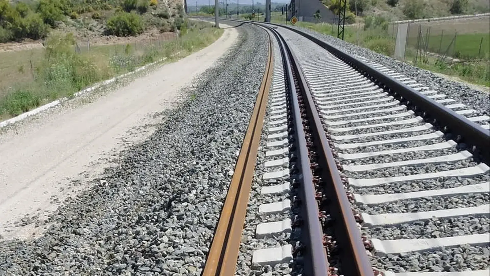
The track is the fundamental infrastructure that allows the movement of trains, designed to support large loads with minimal resistance. For a railway infrastructure to guarantee the safe circulation of rolling stock, particularly on routes demanding high speeds, it is indispensable to have a track of excellent quality, characterized by solid construction and rigorous and systematic maintenance. If the track is in poor condition, the journey becomes uncomfortable and dangerous.
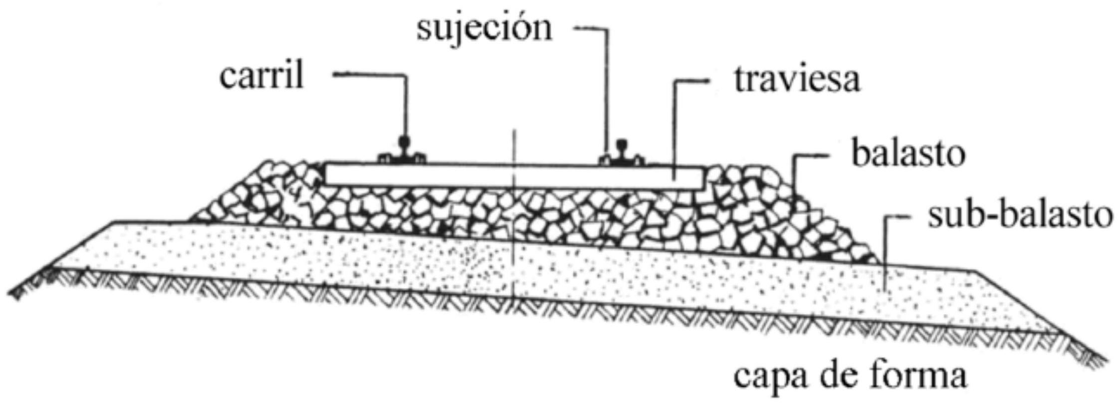
The railway structure is organized into two main components differentiated by their functions and characteristics. The infrastructure constitutes the fundamental base of the system, essentially formed by the platform, which provides structural support and necessary stability. On the other hand, the superstructure or track represents the set of elements resting on the infrastructure that directly interact with the rolling stock.
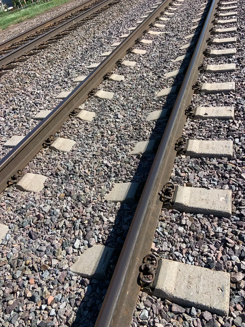
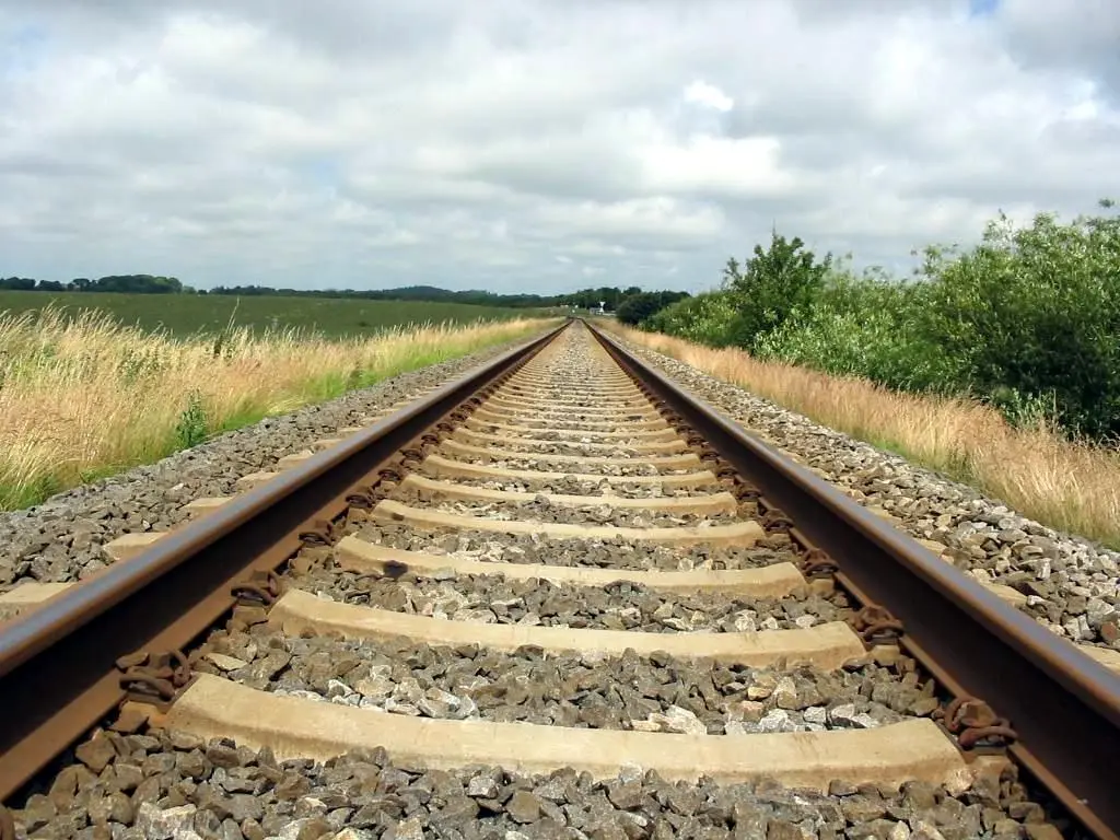
The superstructure is composed of three main functionally integrated elements. First, we find two rows of rails, which act as a guide and running surface for the rolling stock. Sleepers are arranged on these; they are transverse structural elements whose fundamental function is to fix the rails while maintaining the track gauge and mediating in the transmission of loads. Finally, the ballast constitutes the layer of granular material on which the set of sleepers rests, allowing the distribution of stresses towards the platform. Additionally, the system includes various accessories and small track material, such as baseplates, fishplates, fastening elements, and other components that optimize the integral functioning of the system.
Chapter II The Rail: Definition and Historical Origins
The rail constitutes the most critical component and fundamental part of any railway structure, being the only element maintaining direct contact with the rolling stock and, consequently, being the one receiving the entirety of the mechanical stresses generated by the circulating traffic.
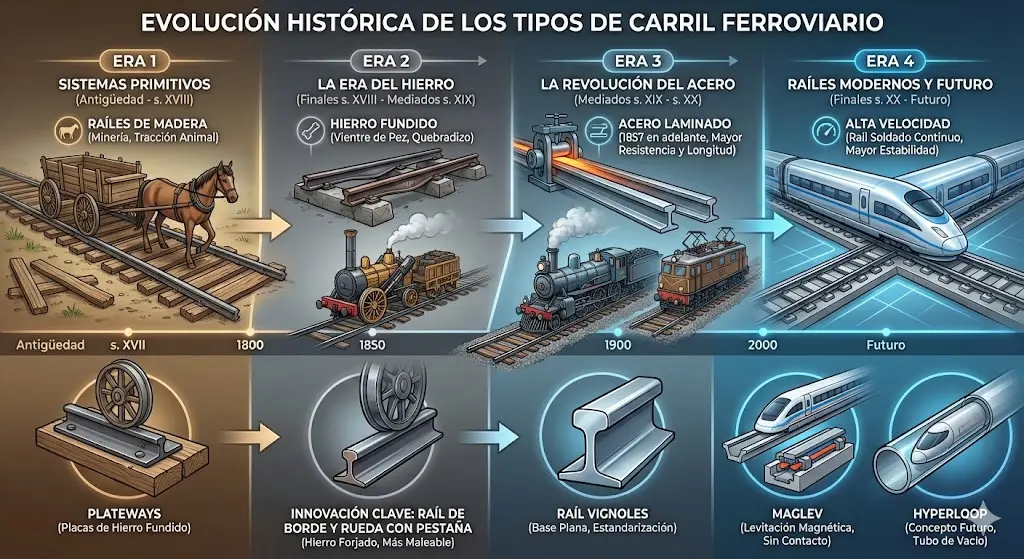
Since ancient times, civilizations have sought engineering solutions to improve freight transport. The ancient Egyptians were pioneers in the development of the metallic rail, using bronze for this purpose, which allowed them to transport large quantities of cargo more efficiently than by conventional land systems.
Subsequent to these first experiences, during the European medieval period, specifically in the German mining industry of the 15th century, a track system was developed consisting of two parallel rows of sawn wooden beams, equipped with a lateral rim serving as a guide for small mining vehicles. This technological advance, which significantly improved mineral transport in mines, was quickly adopted in England and other European territories.

II.1. Definition and Historical Origins
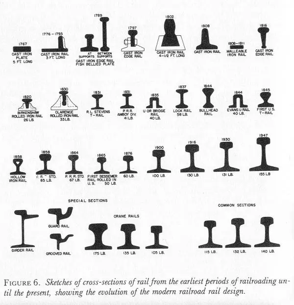
The technological evolution of the railway rail experienced a significant advance during the 18th century, when the substantial reduction in iron prices, derived from improvements in steelmaking processes, made it viable to cover primitive wooden rails with this metal, notably increasing their durability. In 1789, an important milestone occurred with the appearance of the first smooth rails, which worked in combination with lateral flanges incorporated into the outer edge of the rolling stock wheels, thus improving guidance and circulation safety. However, numerous successive modifications and refinements were required to achieve the geometry and characteristics of the modern rail, a process consolidated approximately in 1830.
Regarding the evolution of materials used, the first rails were manufactured with cast iron, a material that demonstrated excessive brittleness in the face of stresses derived from circulation. The application of hot rolling processes improved the toughness of the material, although this advance was still insufficient to contain the accelerated wear produced as a consequence of the simultaneous increase in axle loads and circulation speeds. The introduction of steel as a rail construction material represented a truly revolutionary innovation for the time, allowing for an extraordinary extension of service life: while cast iron rails became unusable after approximately three months of operation, the new steel rails could maintain their functionality for periods reaching 16 years.
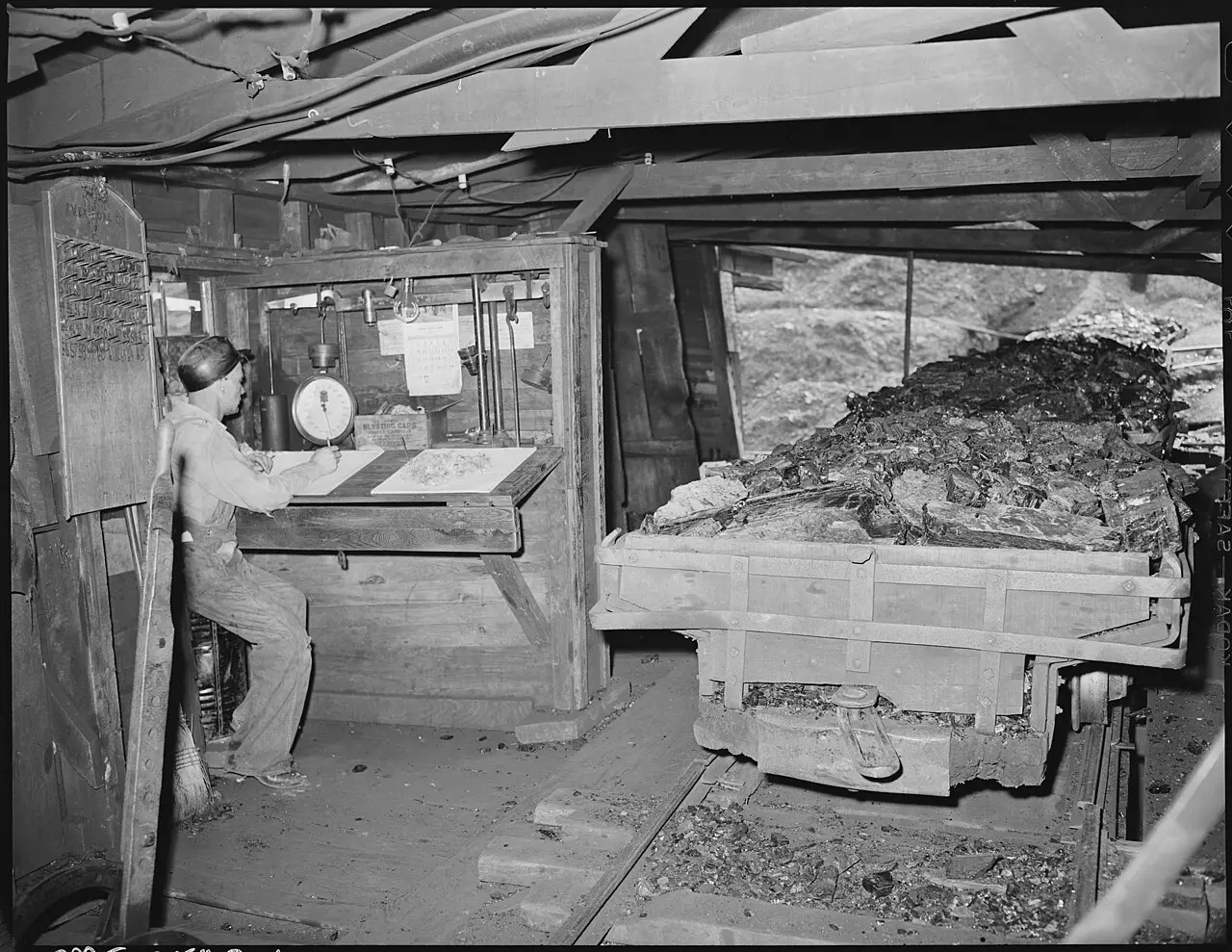
 Courtesy of the Railroad Museum of Pennsylvania
II.2. Functions of the rail
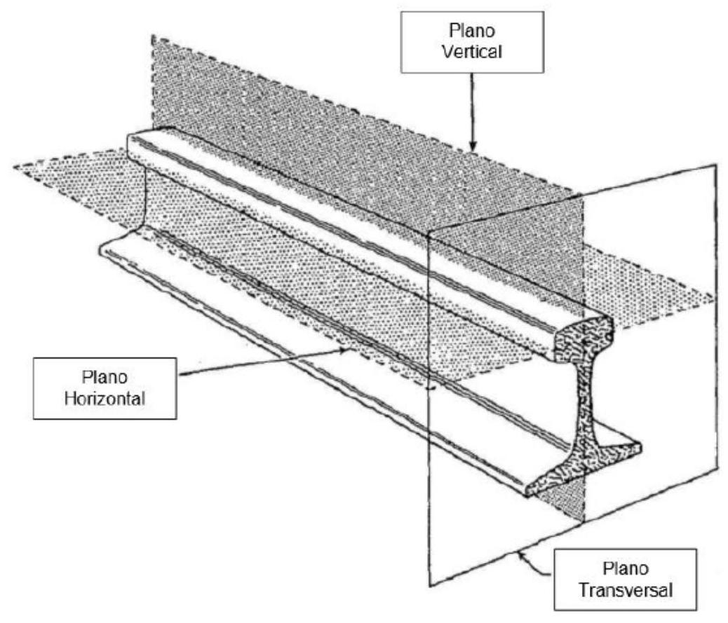
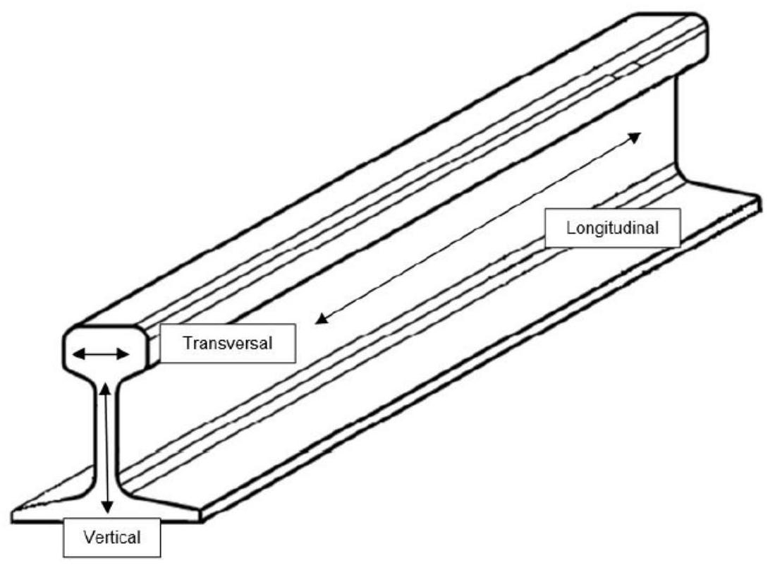
The railway rail performs multiple critical functions for the safe and efficient operation of rail transport. Firstly, the rail acts as a guiding element for the rolling stock, maintaining the correct trajectory in both the horizontal plane (alignment) and the vertical plane (profile), preventing unwanted deviations from the intended route. Simultaneously, it absorbs, supports, and resists all loads transmitted by the circulating traffic, distributing them towards the lower structural elements of the track.
In railway systems with electric traction, the rail fulfills the additional function of conductor of electric current from the catenary to the train motor through the rolling stock wheels. Likewise, by being constituted as the contact surface between wheel and track, it guarantees the metal-metal friction characteristics necessary for the functioning of the traction and braking system.
The stresses acting on the rail derive from the interaction with the rolling stock and geometric imperfections of the track. These can be classified into three main directions: longitudinal stresses, essentially originated by the accelerations and braking of the train, as well as by temperature variations producing expansions and contractions of the material. Vertical stresses originate mainly from the structure’s own weight and the dynamic loads of the rolling stock.
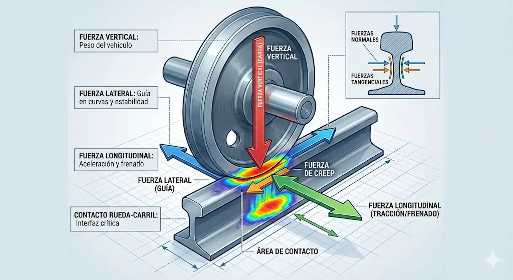
Finally, transverse stresses cause permanent deformations in the running path, being particularly critical because the elastic limit of the material is significantly lower in this direction.
II.3. Rail cross-section
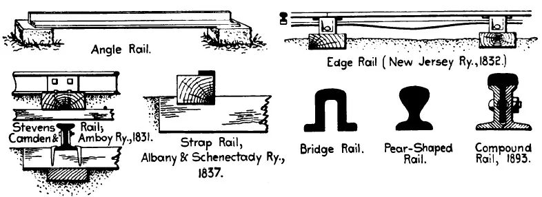
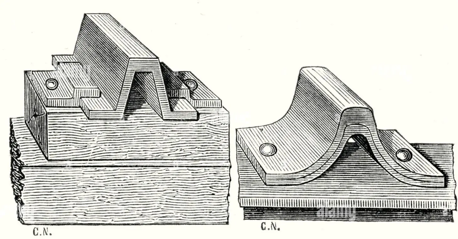
At the dawn of locomotive use, the rail had to adapt to stresses derived from progressively higher speeds, thus adopting a variable section. This particular configuration received the name of fish-belly rail, whose shape allowed for better stress distribution. Initially, it rested on natural stone blocks, as shown in historical references up to 1835, these supports being subsequently replaced by metallic devices such as chairs and plates, and finally by wooden sleepers. However, the technical difficulties inherent to the manufacturing process of this type of rail eliminated any economic advantage that might have been expected, leading to the abandonment of this solution.
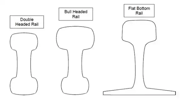
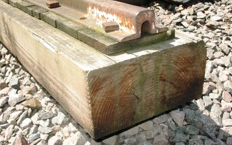
Subsequent evolution led to the development of rails with constant section, designed to fulfill multiple functions simultaneously. On one hand, the rail must act as a resistant beam capable of supporting both vertical and transverse loads; theoretically, an I-beam section would be optimal for this function. On the other hand, it must function as a guide for the rolling stock wheels, requiring a specific geometry in its head. Various profiles were developed throughout railway history, although most were ephemeral in their use. Only two configurations managed to remain current: the bull-head rail and the Vignole rail. The bull-head rail, also called Stephenson rail or chair rail, uses a fixation system based on a cast iron or molded steel chair, inside which the rail is held by wooden or metal wedges, providing effective and resilient clamping.
II.3.1. Bull-head rail
The bull-head rail existed in two section variants: one symmetric and one asymmetric. The symmetric configuration was initially based on the hypothesis that, once the upper head of the rail was worn by the passage of traffic, it would be possible to invert the rail and use its lower face as a new running surface, thus maximizing material utilization. However, practice demonstrated that this strategy was unfeasible, as the fixation system using chairs and wedges left marks, notches, and permanent impressions on the lower face of the rail during normal use, making its subsequent use as a running surface impossible.
For this reason, only the asymmetric variant was commercially exploited, offering the economic advantage of not requiring additional material in the lower head, destined for wear, but concentrating the entire metal reserve in the upper head.
The bull-head rail presented several comparative advantages over the Vignole type flat-bottom rail that justified its generalized adoption on all English lines, as well as on certain French railway companies (the Southern and Western lines) and on the Swiss railway. Among its main advantages were:
-
A more balanced distribution of material between the two heads and the web, in contrast to the very asymmetric distribution characteristic of the flat-bottom rail. This more favorable distribution allowed rolling, cooling, and straightening processes to be carried out under more optimal and controlled conditions.
-
A lower tendency for pull-out of the fastening screws (coach screws), since the sleeper lifting effort produced by the passage of loads was transmitted with less intensity. This was due to the rail being held by wedges providing a certain inherent elasticity, preventing the screws from progressively loosening.
-
Greater ease in renewal operations of the track and rail replacement, since the sleepers came already equipped with the chairs installed from the factory, reducing field work solely to rail placement and its fixation via wedges. This characteristic also contributed to lower conservation and maintenance costs of the joint system.
-
Greater structural stability under transverse stresses, which largely depends on the specific type of fastening employed.
-
The possibility of using soft wood sleepers, thanks to the chair providing a support surface that can reach up to 680 cm², distributing pressure more favorably. This possibility does not exist with the Vignole rail when the foot rests directly on the sleeper without intermediate elements.
Despite all these technical advantages, the bull-head rail is currently not used for the construction of new railway lines. English railways, which were its last defenders, abandoned it progressively around 1938. Nevertheless, it continues to provide service on secondary and shunting lines, particularly in France on the old Southern and Western lines. The fundamental cause of its obsolescence was the high manufacturing cost of the chair compared to conventional screws, as well as the inherent complexity of maintaining the geometric alignment of the track with this system.
II.3.2. The Vignole type rail
The flat-bottom rail, designated in Europe as Vignole rail in honor of the English engineer Charles Vignoles who introduced it to the European continent (although its original concept was developed by the American engineer Stevens), became the predominant solution on most modern railway lines. Its specific geometry was conditioned by the functional need to employ joint bars (fishplates) to connect consecutive rails.
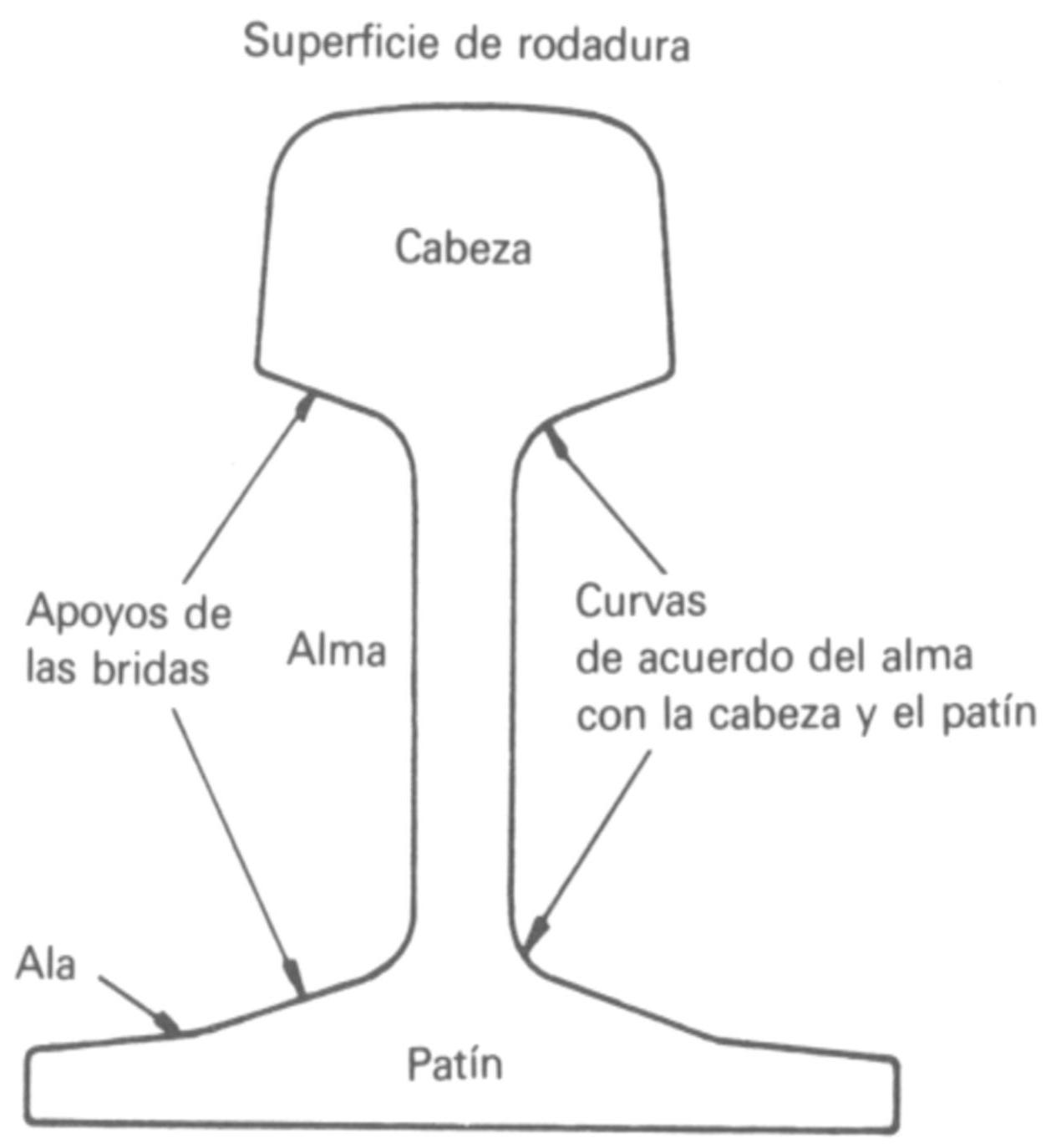
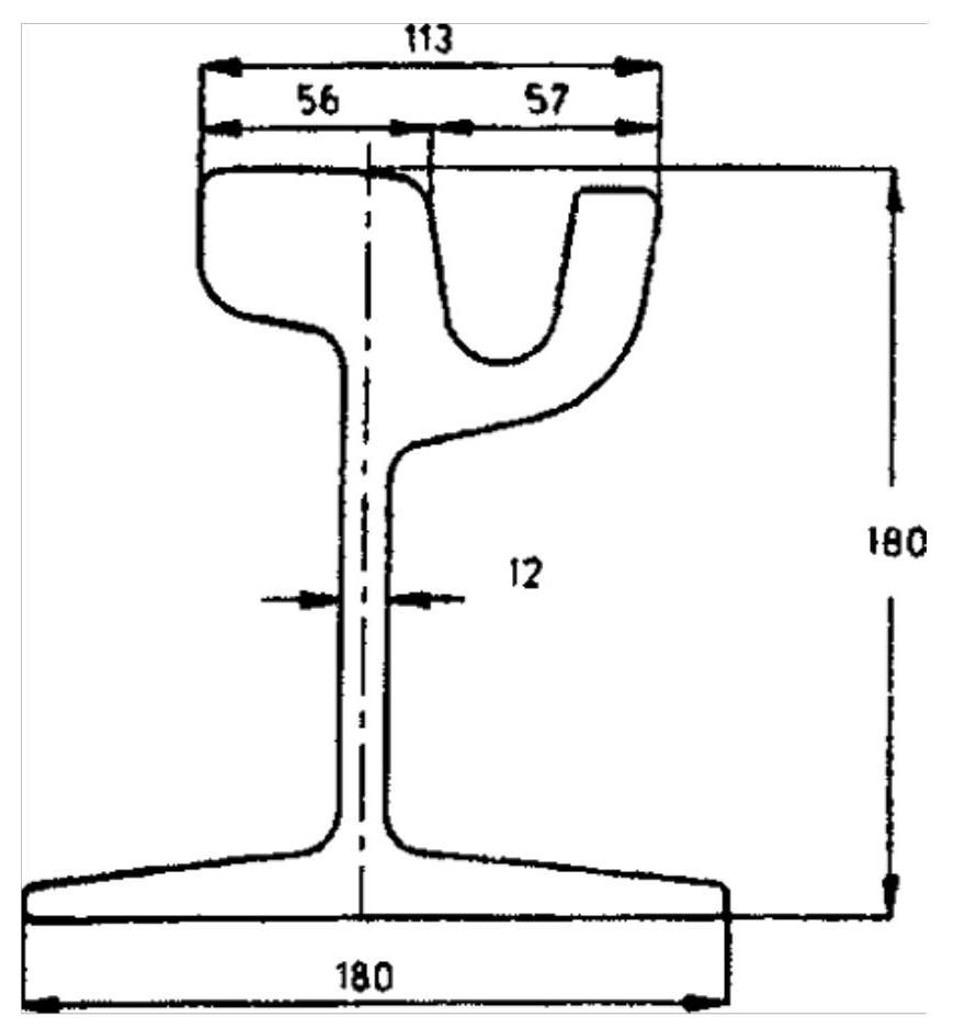
The Vignole rail is composed of three main structural components, each with specific and differentiated functions. The head constitutes the upper part of the rail, responsible for transmitting stresses derived from circulation and preventing derailment through its inclined lateral faces, which prevent excessive lateral displacements of the rolling stock. The web is the intermediate component transmitting tension from the head to the lower foot, providing simultaneously sufficient vertical inertia to ensure adequate bending resistance under loads. Finally, the foot (or base) constitutes the support base of the rail, whose function is to distribute loads onto the sleeper, prevent structural overturning under transverse stresses, and provide the necessary support for fastening elements.
Regarding the specific geometry of the rail head, several critical dimensional parameters must be carefully defined. The head height typically reaches 50 millimeters and must be greater than strictly required by structural resistance conditions, providing an additional material reserve to absorb progressive wear during service life. As a reference order of magnitude, it can be established that the rail head suffers a height loss of approximately one millimeter for every one hundred thousand trains circulating over it, considering millions of gross tons of load.
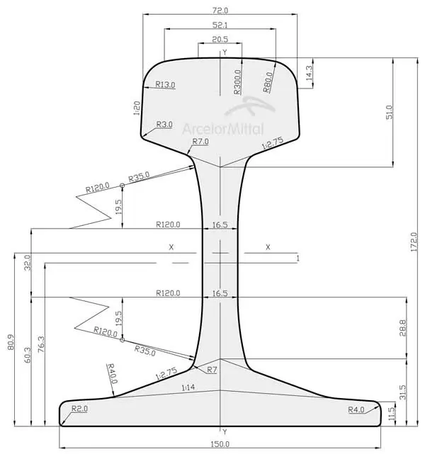
DIMENSIONS IN MILLIMETERS
UIC-60-E1 RAIL
 ArcelorMittal
The camber (crowning) is a fundamental geometric aspect of the rail head, consisting of a transverse curvature with a radius of curvature \(R=300 \mathrm{~mm}\). This convex configuration is essential to prevent various defects that would arise if the running table were completely flat. Among these avoided defects is the appearance of lateral burrs, which tend to exfoliate and detach progressively, degrading surface quality. Furthermore, with a flat surface, a significant difference in linear velocities would be produced between the distinct points of the rolling stock wheel flange cone generatrix when these enter into contact with the rail plane, generating accelerated and differential wear.
The inclination of the lateral faces of the rail head is a critical geometric parameter that must allow that during circulation on straight alignment there is no contact between the wheel flange and the inner face of the rails, avoiding unnecessary chafing. However, in small radius curves, contact between the wheel flange and the lateral face of the rail head is inevitable, a zone where lubricators are frequently installed to reduce friction and lateral wear.
To significantly reduce contact pressure between wheel and rail, and thus mitigate the consequent accelerated wear, the lateral faces of the head are inclined following a slope of 1/20 (i.e., 5%). This inclination presents, in addition to its immediate advantage of pressure reduction, the additional advantage of increasing the effective width of the lower head faces, notably improving the coupling of joint bars connecting consecutive rails. The angle of inclination of the inclined planes forming the junction between the head and the web of the rail (typically adopted in a 1/3 ratio with respect to the horizontal) is deeply justified when addressing the specific topic of joint bars and their functions.
Regarding the rail web, its dimensioning must carefully consider the shear stresses traversing this region. Maximum shear stresses are located in the plane coinciding with the neutral fiber of the section, that is, in the vicinity of holes made for joining. Additionally, the web thickness must be designed to resist wear by progressive corrosion. For these reasons, except in tunnel zones where protection is greater, a thickness in the range of 15-17 millimeters is typically adopted.
The shape of the web lateral walls does not respond to simple vertical straight lines. This geometry obeys the fact that the rail must support significant transverse stresses transmitted by wheel flanges, behaving structurally as a piece embedded in the lower foot. Consequently, the web presents a greater thickness at its junction with the foot regarding the minimum thickness required at the neutral axis. An equivalently increased thickness is provided in the junction zone between web and head, due to the high number of breaks detected in this stress concentration region if this design precaution is not taken. The lateral faces of the web thus adopt the form of concave surfaces, with their minimum thickness coinciding precisely at the neutral axis of the section. The foot is characterized primarily by its width and by the specific shape and thickness of its lateral wings. The foot width largely determines the rail stiffness in the horizontal plane, influencing its resistance to transverse deformations. Simultaneously, the foot width determines the available support surface on the underlying sleeper, and therefore the contact pressure exerted on the latter. Contact pressure can be reduced by using metal baseplates that interpose a more favorable load distribution. To guarantee correct load distribution without promoting unwanted rail twisting on its support, it is essential to find an optimal relationship between the total rail height and the foot width, a relationship that should ideally be situated in the 1.1-1.2 interval.
The tendency for lateral rail overturning under the action of flange forces and other stresses resulting in rail-sleeper connections is directly a function of this previously mentioned height-width relationship.
The specific thickness and shape of the foot wings are conditioned by the need to achieve an adequate structural balance between the foot section and the rail head section. This balance is fundamental to ensure good rolling conditions during hot rail manufacturing and uniform cooling avoiding residual deformations.
DIMENSIONS IN MILLIMETERS
There are other additional characteristics of the rail cross-section deserving special consideration. Shear stress is a critical parameter to verify in design. A particularly important aspect is achieving an adequate mass distribution along the main rail components -head, web, and foot- such that upon finalizing the rolling process the resulting structure is homogeneous throughout its extension. This mass balance is crucial to ensure that during subsequent steel cooling there are no significant behavioral differences between the different section parts. This phenomenon is especially important because rails manufactured without this mass balance tend to curve during cooling post-rolling, developing residual deformations compromising their functionality. Industrial research and practices have confirmed that the most appropriate mass distribution is one where the head constitutes 35-40% of the total mass, the web 27-32%, and the foot 38%.
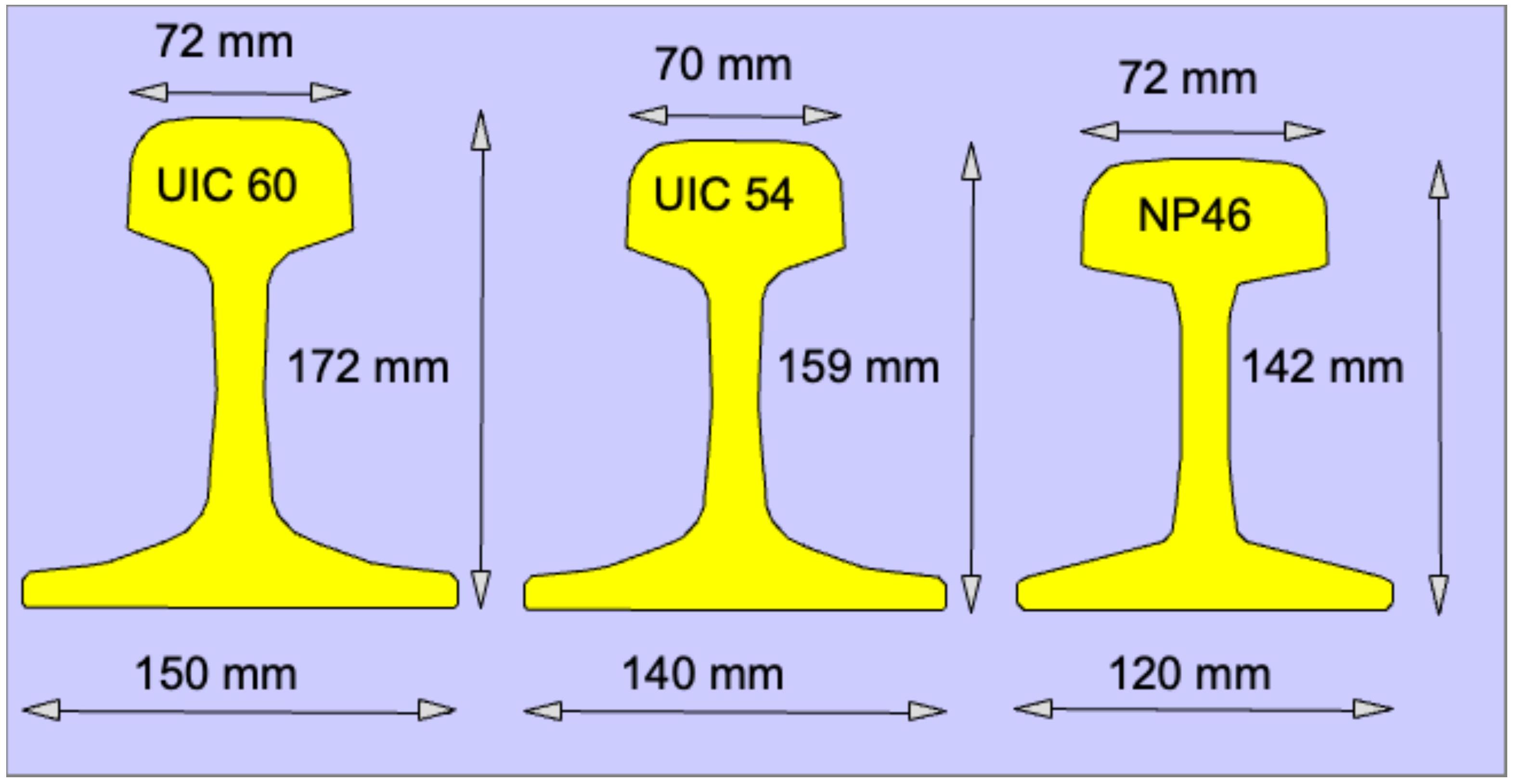
Regardless of its geometric configuration, the essential characteristic defining a rail is its weight per unit of length, conventionally expressed in kilograms per linear meter (or in pounds per yard in Anglophone and US countries).
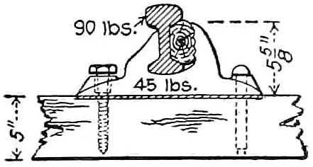
Rail profiles initially used in the first phase of the railway industry were significantly lighter, of the order of 25 kilograms per linear meter, being necessary to wait until the 20th century to witness the appearance of more substantial profiles in the 40-50 kg/m range. During this same historical period, maximum axle loads of vehicles experienced a spectacular increase, going from a modest 3 tons per axle to current 20-22 tons per axle. Currently, it is common to find rails weighing between 60-70 kg/m, and even 90 kg/m profiles are used on certain US lines subjected to extremely heavy traffic.
The predominant tendency in the modern railway industry is the preferential use of heavy rails, motivated fundamentally by the notable reduction these achieve in conservation and maintenance expenses throughout the infrastructure’s service life.
The technical objective pursued by progressively increasing the rail weight is to increase its moment of inertia (calculated with respect to its neutral fiber, \(I_{\chi}\)), that is, maximize its section modulus \(W\). This metric is fundamental for the rail’s capacity to resist bending under loads.
From a design perspective, one of the main challenges is achieving, with the same weight and therefore the same manufacturing cost, cross-sections possessing a greater moment of inertia and section modulus.
In reality, the critical problem in rail design is not solely resistance but fundamentally progressive wear. Consequently, in the project of a new railway line one must simultaneously consider: the adaptation of the chosen rail profile to the total expected traffic volume \(T\) circulating on that track, expressed in millions of gross tons, the expected maximum speed \(V\), and the axle weight \(q\) of vehicles using the line. An empirical formula that has demonstrated practical utility is Shajunianz’s (1971):
\[P=1,2 \cdot\left(1+T^{1 / 4}\right) \cdot(1+0,012 \cdot V)^{2 / 3} \cdot q^{2 / 3}\]Additionally, it is recommended to guarantee that the rail-sleeper set possesses a balanced service life, avoiding premature renovations of one component when the other could still maintain its functionality. For reference, French regulations establish the following recommended correlations:
| GROSS TOWED TONS (G.T.T.) | RAIL TYPE | SLEEPER TYPE |
|---|---|---|
| G.T.T. < 25,000 | \(50 \mathrm{~kg} / \mathrm{m}\) | Wooden sleeper |
| 25,000 < G.T.T. < 35,000 | \(50 \mathrm{~kg} / \mathrm{m}\) | Wooden sleeper |
| \(60 \mathrm{~kg} / \mathrm{m}\) | Concrete sleeper | |
| G.T.T. > 35,000 | \(60 \mathrm{~kg} / \mathrm{m}\) | Concrete sleeper |
II.3.3. Other rail types
Besides the two main types mentioned, there are specialized rail profiles designed for specific applications in different operational contexts. Among the most notable are:
The Phoenix rail, also called grooved rail or girder rail, constitutes a special solution designed for situations where it is necessary to allow road vehicles to circulate on the same platform without obstacles. Its geometric configuration prevents interference with normal road vehicle rolling by being arranged strategically with respect to the circulation level. The use of the Phoenix rail turns out to be economically more advantageous than the traditional alternative of installing additional check rails to resolve this mixed-use conflict.
The Brunel rail, characterized by a considerably reduced height compared to standard Vignole rails, represents a simplified version practically eliminating the rail web. This type is preferentially used in secondary track accessory devices, such as turntables and swing bridges, where resistance requirements are significantly lower than on the main track.
II.4. Demands placed on the rail
Railway rails must satisfy a set of rigorous technical demands, both in terms of fundamental characteristics and specific operational functionalities.
Regarding fundamental demands, rail geometry stands out firstly, which must comply with extraordinarily strict tolerances to ensure correct rolling stock guidance and uniform stress distribution. Mechanical properties constitute a second fundamental requirement, particularly the rail’s vertical inertia, determining its bending resistance capacity under loads. The commercial length of the rail must be maintained within precise specifications. Rail straightening after rolling is equally critical, guaranteeing the absence of residual curvatures or twists.
Additionally, there are further functional demands conditioning material selection and acceptance. The rail must present a complete absence of brittleness, not presenting brittle fractures under normal service conditions. Steel weldability is fundamental, especially in long-term continuous welded rail systems. Manufacturing process simplicity and economy are determining factors in selecting the steel type and metallurgical procedure used.
II.5. Composition
Since approximately the mid-19th century, the structural material used in rail manufacturing is steel. However, properties required in railway steel present contradictory and often conflicting requirements among themselves. A steel that must possess high wear resistance must necessarily be hard in its crystal structure, a characteristic inherently carrying a tendency towards brittleness and significantly hindering its welding capacity. Consequently, steel used in rails must necessarily represent a carefully balanced compromise between these mutually contradicting demands.
Without delving into the complete metallurgical analysis of steel used in rails, the typical chemical composition of railway steel includes the following main elements:
Carbon, present in proportions ranging between 0.37 and 0.73 percent by weight, acts as a steel hardening element. Its presence significantly increases material hardness and abrasive wear resistance, although simultaneously increasing inherent brittleness, reducing structure toughness.
Manganese, typically present in concentrations between 0.86 and 1.74 percent, acts as a secondary strengthening element. It increases steel hardness, improves wear resistance, and also increases the general toughness of the material. However, it presents the drawback of notably decreasing steel weldability, complicating joining processes between elements.
Sulfur and phosphorus, present in concentrations below 0.06 percent each, are residual elements inherent to production processes. Although they carry significant disadvantages in terms of material brittleness, they are practically uneliminable from conventional steelmaking processes without incurring prohibitive additional refining costs.
Silicon, typically present in a proportion of 0.30 percent, increases steel hardness and wear resistance, also facilitating hot rail rolling processes.
Rail
| Grade | Sample | C | Si | Mn | P max. | S max. | Cr | Al max. | V max. | N max. | O | H |
|---|---|---|---|---|---|---|---|---|---|---|---|---|
| R260 | Liquid | 0.62-0.80 | 0.15-0.58 | 0.70-1.20 | 0.025 | 0.025 | ≤0.15 | 0.004 | 0.030 | 0.009 | 20 ppm | 2.5 ppm |
| Solid | 0.60-0.82 | 0.13-0.60 | 0.65-1.25 | 0.030 | 0.030 | ≤0.15 | 0.004 | 0.030 | 0.010 | 20 ppm | 2.5 ppm | |
| R350HT | Liquid | 0.72-0.80 | 0.15-0.58 | 0.70-1.20 | 0.020 | 0.025 | ≤0.15 | 0.004 | 0.030 | 0.009 | 20 ppm | 2.5 ppm |
| Solid | 0.70-0.82 | 0.13-0.60 | 0.65-1.25 | 0.025 | 0.030 | ≤0.15 | 0.004 | 0.030 | 0.010 | 20 ppm | 2.5 ppm |
Note: Values in % by mass except O and H expressed in ppm (10⁻⁴ %)
Table 3. Chemical composition of steel
| Mo | Ni | Cu | Sn | Sb | Ti | Nb | Cu and Sn | Others | |
|---|---|---|---|---|---|---|---|---|---|
| R260 | 0.02 | 0.1 | 0.15 | 0.03 | 0.02 | 0.025 | 0.01 | 0.35 | 0.35(Cr+Mo+Ni+Cu+V) |
| R350HT | 0.02 | 0.1 | 0.15 | 0.03 | 0.02 | 0.025 | 0.04 | 0.35 | 0.25(Cr+Mo+Ni+Cu+V) |
Table 4. Maximums of residual elements
II.6. Manufacturing
The rail manufacturing process from the ingot or bloom coming from the steel mill head installations is structured into several differentiated and sequentially organized technological processes:
The hot process constitutes the first main stage, consisting of steel rolling at elevated temperatures in the approximate range of 1250°C to 920°C. During this stage, the material is progressively deformed to adopt the definitive rail profile geometry through successive rolling passes.
Subsequently, the cooling process is executed, which can be performed using two distinct methodologies depending on the type of rail desired. Air cooling constitutes the conventional option used to manufacture standard rails, allowing heat to dissipate naturally into the atmosphere. Alternatively, controlled cooling is applied when manufacturing head-hardened rails is required, in which cooling temperature is carefully regulated in the approximate range of 750°C to 500°C via specialized systems, allowing specific metallurgical characteristics to be achieved in the surface layer.
Finally, the cold process (at temperatures below 80°C) includes multiple finishing operations: straightening of the rail to correct any residual deformation, automatic inspection via sensor systems to detect defects, cutting to specified commercial lengths, pressing of rail ends, manual inspection by specialized personnel, followed by storage, loading, and shipping of finished rails.
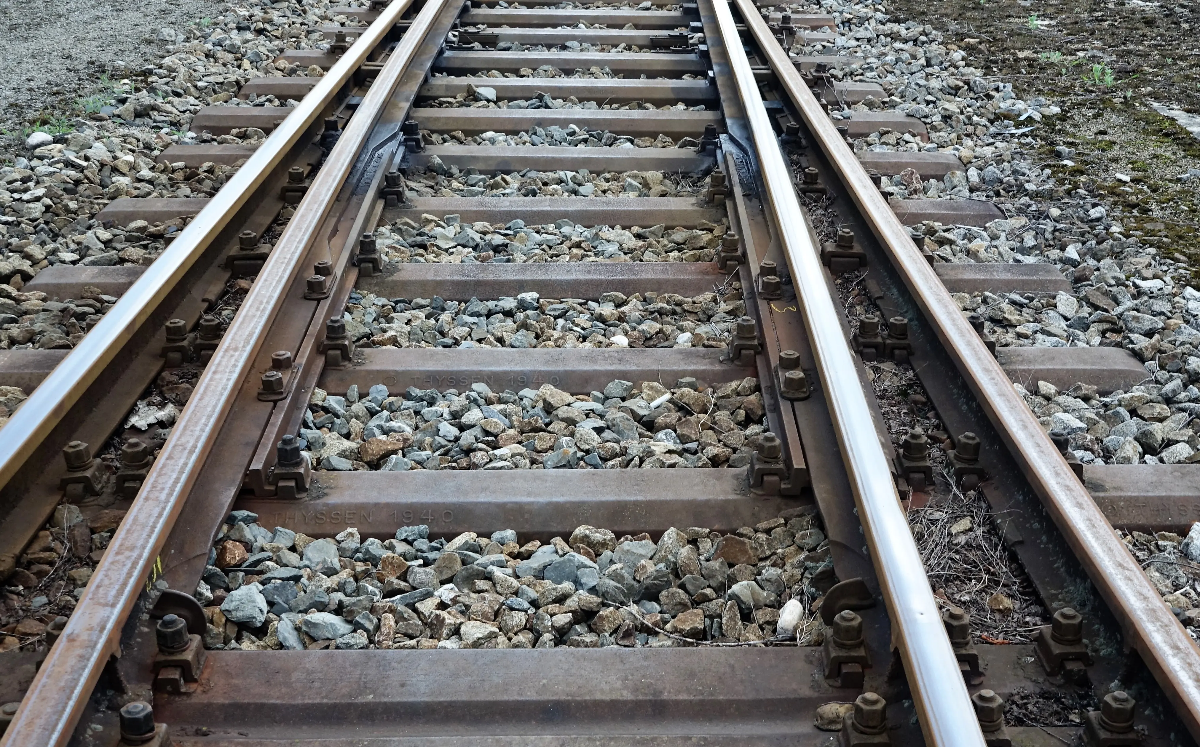
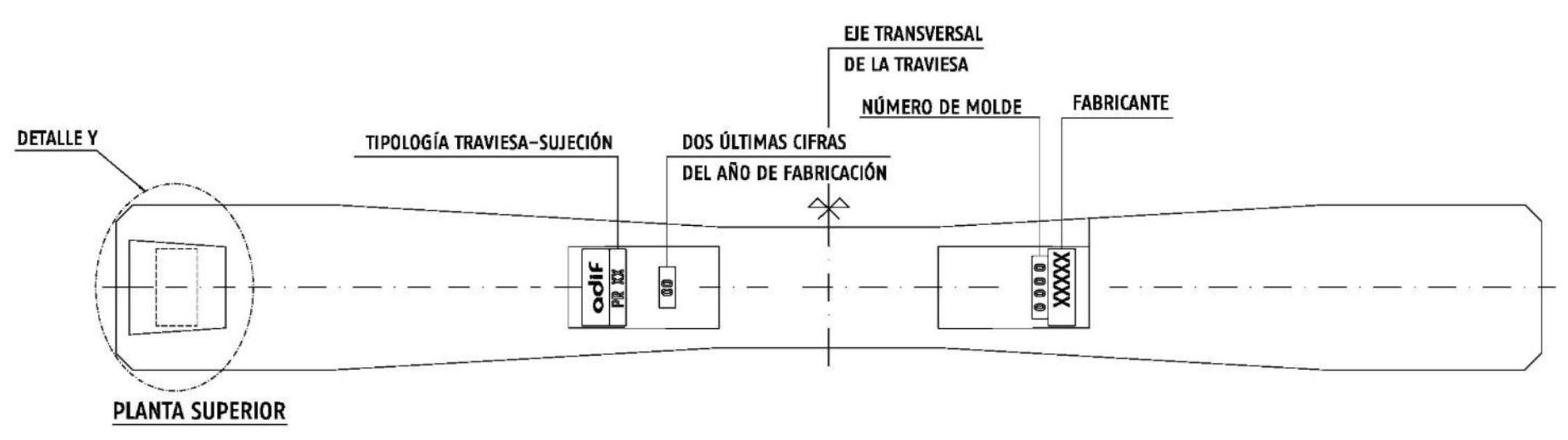
II.7. Reception
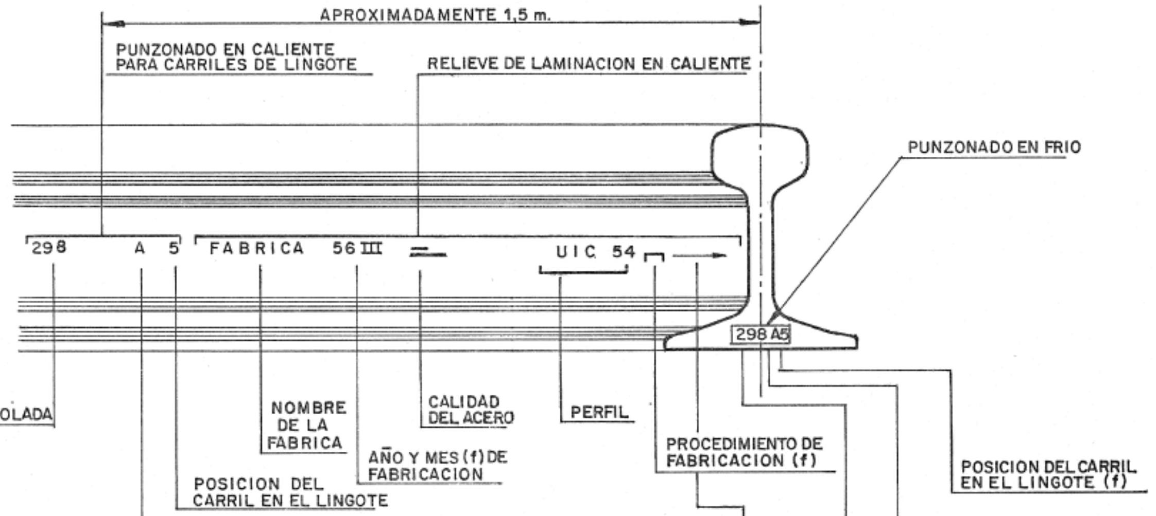
The set of marks and identifications permanently inscribed on the rail web during the hot rolling process is called “christening” (branding). These marks fulfill the critical function of allowing individual identification and traceability of each rail manufactured, facilitating the adoption of structured safety measures in case breaks occur during the rail’s service life.
Marks engraved on the rail web contain coded technical information allowing identification of: the manufacturer responsible for production, the specific year of manufacture, the month within that year, the quality classification of the steel used, the steelmaking procedure or process employed in manufacturing, the specific rail profile type, the original ingot direction via an indicator arrow, the unique heat number (identified with letters A to Z), the relative position of the specific rail within the original ingot, and the unique ingot identifier number.
II.8. Transport
Manufactured rails, depending on their length, require transport via distinct transport modes presenting specific limitations regarding maximum handleable lengths economically.
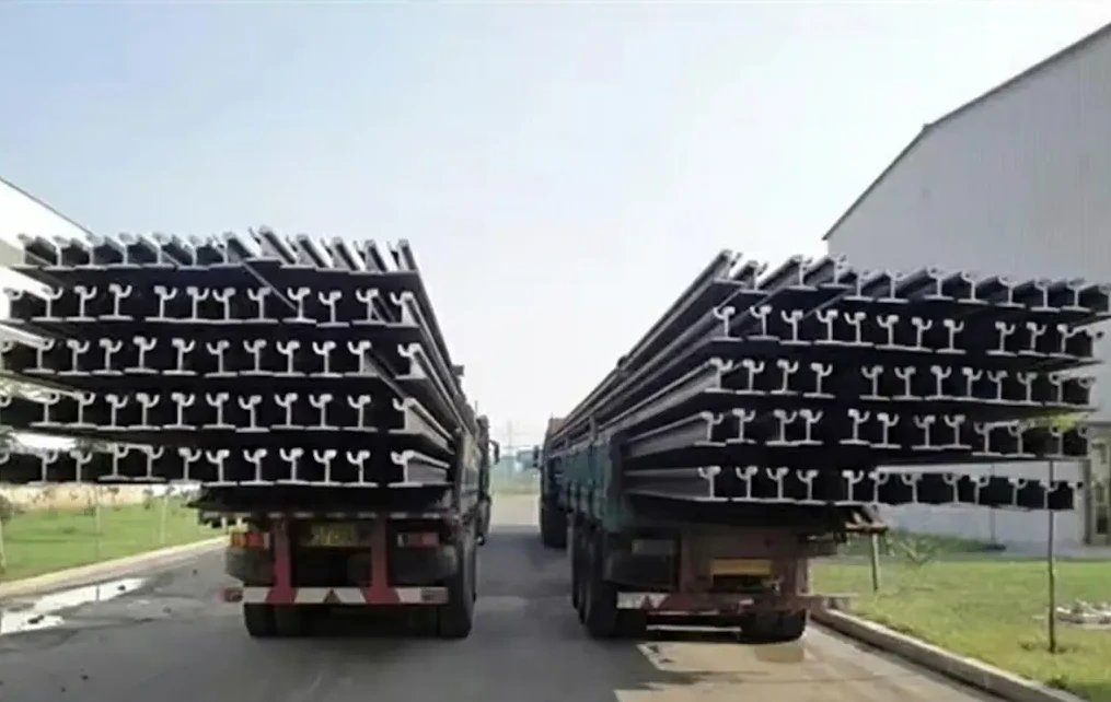
Truck transport constitutes the appropriate modality for rails up to 25 meters in length, using closed-box vehicles for this purpose providing protection against atmospheric agents during transport.
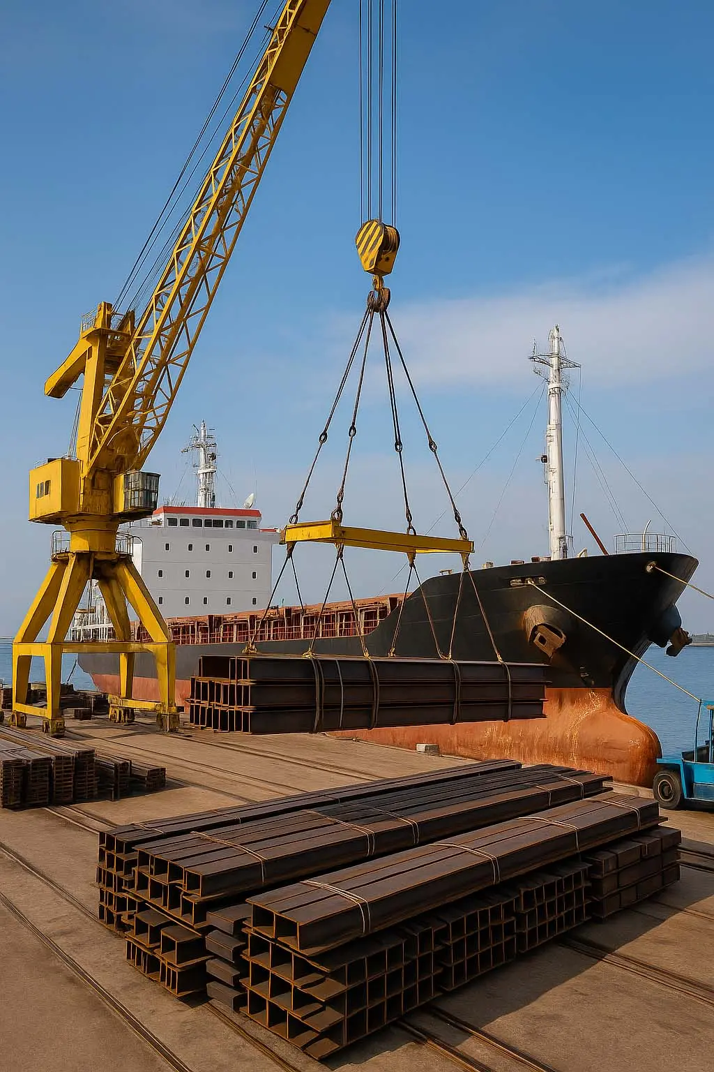
Maritime transport via ships proves economically viable for rails reaching lengths of up to 72 meters, allowing international transfers of large volumes of railway material.
Rail transport, using specialized wagons of the railway system itself, constitutes the most economically efficient option for longer rails. It allows the transport of elemental bars up to 108-120 meters long, and especially relevantly, enables the transport of long welded bars with lengths up to 270-288 meters, these latter constituting the strategy of maximum economy for distributing large quantities of rail.
 Closed Box Truck
 Ship
Ship
Railway
II.9. Tests
Railway rails must undergo a rigorous set of quality control tests characterizing their metallurgical and mechanical properties. Fundamental tests defining rail quality include:
Chemical composition analysis to verify that percentages of carbon, manganese, silicon, and other elements are within specified ranges. Microstructure examination and evaluation of surface decarburization degree. Inspection via metallographic techniques to detect solid or gaseous inclusions present in steel. Baumann test consisting of a macrographic impression revealing internal defects. Hardness tests via Brinell or Vickers techniques. Tensile tests to determine breaking strength and material elongation.
Adif - ET 03.360.161.8 Rail
Additionally, supplementary tests may be required in certain regulations or specifications of specific railway administrations, including:
Impact tests (Charpy) to evaluate material behavior under dynamic loads. Resilience measurements to determine the material’s capacity to absorb energy without fracturing.
| Laboratory test | Section | Steel grades | Test location | |
|---|---|---|---|---|
| R260 | R 350 HT | |||
| Chemical composition | 7.1 | One per heat | Factory Laboratory | |
| Hydrogen | 7.1.1 | One per heat (two from the first heat of a sequence) | ||
| Total oxygen | 7.1.2 | One per sequence \({ }^{\mathrm{a}}\) | ||
| Decarburization | 7.3 | One per 1000 tons or fraction \({ }^{\mathrm{a}, \mathrm{b}}\) | One per 500 tons of annealed and hot-formed steel \({ }^{\mathrm{a}, \mathrm{c}}\) | |
| Oxide cleanliness or inclusionary purity | 7.4 | One per sequence \({ }^{\text {b or c }}\) | ||
| Macrographic inspection (Segregation) | 7.5 | 5 tests in 5 heats (except for RN45 rail) | ||
| Micrography | 7.2 | - | One every 100 tons of hot steel \({ }^{\text {a and c }}\) | |
| Tensile | 7.7 | One calculation per heat/one per 2000 tons \({ }^{\mathrm{a}, \mathrm{b}}\) | One per 1000 tons \({ }^{\text {a,c }}\) | |
| Hardness | 7.6 | One per heat \({ }^{\mathrm{a}, \mathrm{b}}\) | One per 100 tons of hot-formed steel \({ }^{\mathrm{a}, \mathrm{c}}\) | |
| Hardness variation in running surface axis | 7.6.1 | - | One sample of one meter at each end and at 20 m intervals from one rail end (every 5 years). | |
| Fracture toughness ( \(\mathbf{K}_{\mathbf{l} \boldsymbol{c}}\) ) | 7.8 | 5 tests for each of the 3 samples (every 5 years) | Accredited Laboratory | |
| Fatigue crack propagation rate | 7.9 | 3 tests for each of the 3 samples (every 5 years) | ||
| Fatigue test | 7.10 | 3 tests in each of the 3 samples (every 5 years) | ||
| Residual stresses on rail foot | 7.11 | 1 test in each of the 6 samples (every 5 years) |
\({ }^{\text {a }}\) Samples must be taken randomly, but only from rails coming from blooms of the mixing zone between heats, in case of continuous casting in sequence \({ }^{\mathrm{b}}\) Samples must be cut after rolling \({ }^{\mathrm{c}}\) Samples must be cut in heat-treated rails.
II.10. Rail defects and breaks
A rail defect is designated as any structural, dimensional, or metallurgical anomaly presented by the railway profile. Rigorous defect control is vitally important, not only from a purely economic perspective of maximizing service life, but fundamentally for operational safety reasons. The existence of defects can lead, under the action of cyclic stresses produced by circulating traffic, to progressive breakdowns and even catastrophic rail breaks compromising circulation safety.
Rail defects can be classified into two fundamental categories: those originating during the manufacturing process in the steelworks, and those generated and developed during the operational service of the infrastructure.
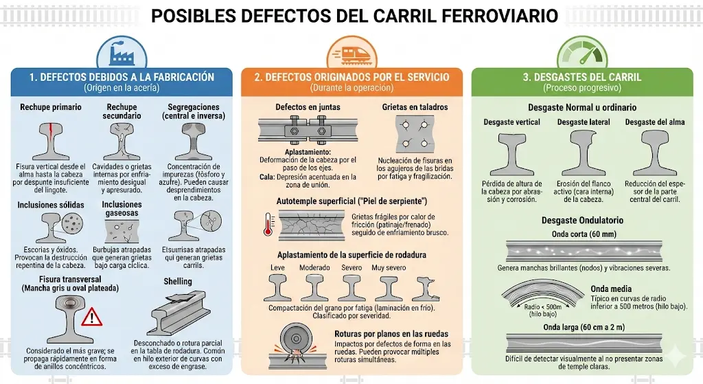
Defects due to manufacturing:
Primary piping constitutes a serious defect originated by insufficient cropping of the ingot during the casting process. It generally produces a vertical fissure extending from the rail web to the head, compromising structural integrity.
Secondary piping results from excessive haste in casting operations. It produces internal cavities or cracks generated by uneven thermal contraction stresses during cooling.
Segregations (both central and inverse) are generated by the presence of impurities, particularly phosphorus and sulfur, which are not distributed uniformly during solidification. These can lead to the formation of deep longitudinal cracks with partial detachment of the rail head.
Solid and gaseous inclusions take another serious type of defect. Solid inclusions consist of slags and oxides of manganese and sulfur, as well as iron and manganese silicates that can cause sudden and localized destruction of the rail head. Gaseous inclusions originate from gases trapped in the ingot during solidification, forming elongated bubbles that can generate future cracks under cyclic stress.
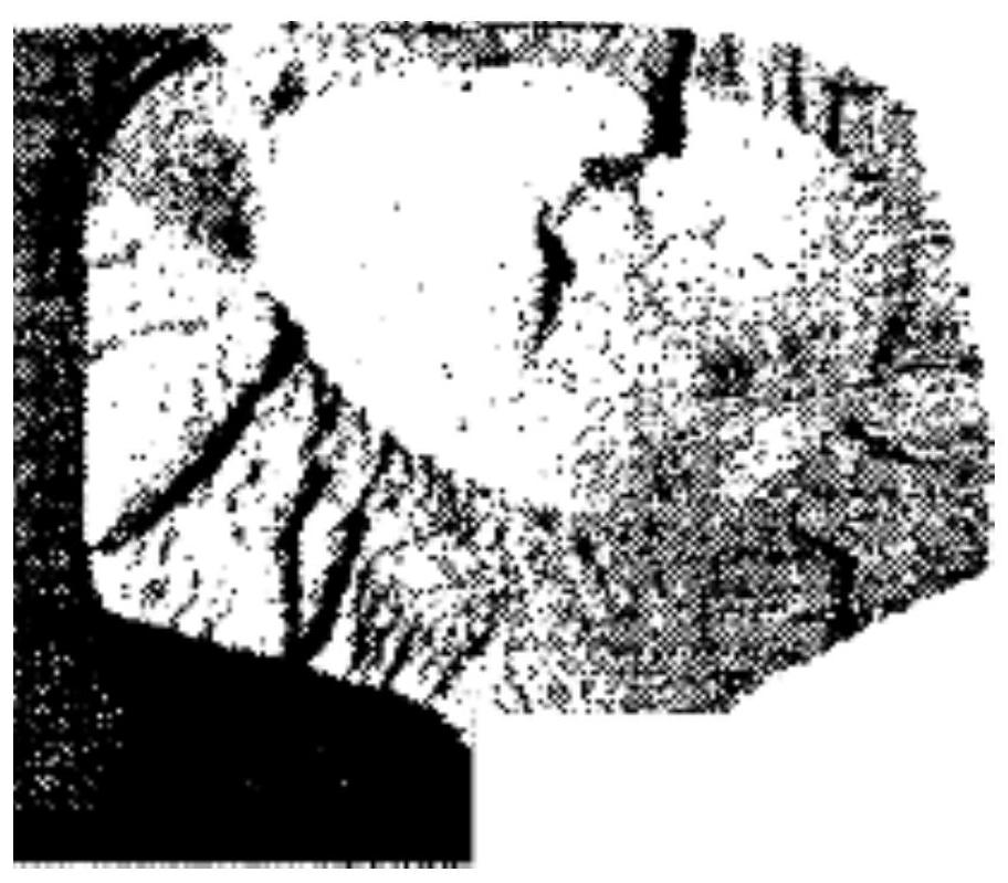
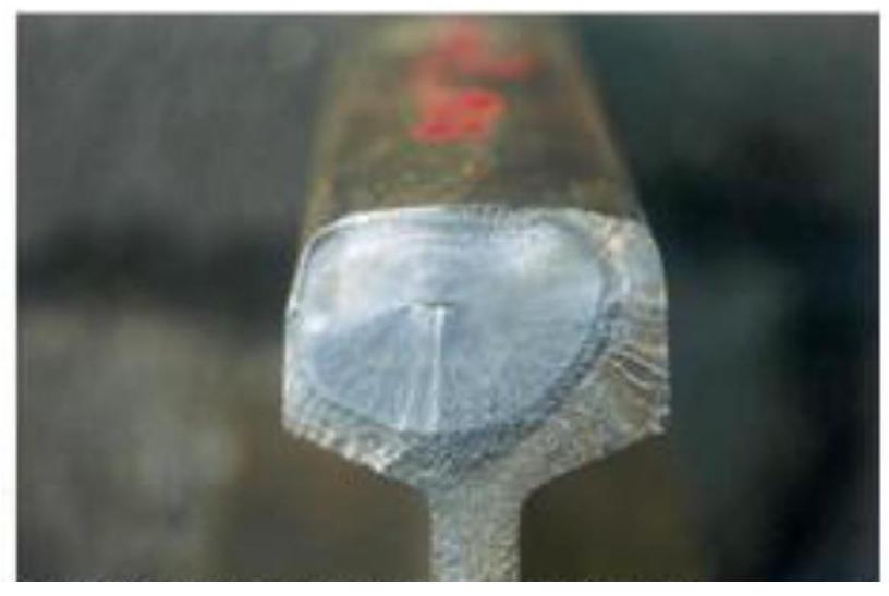
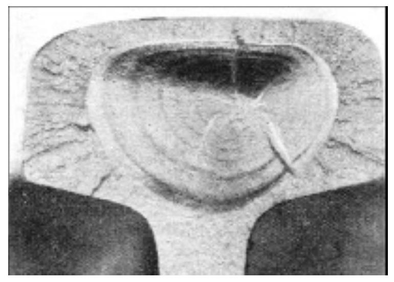
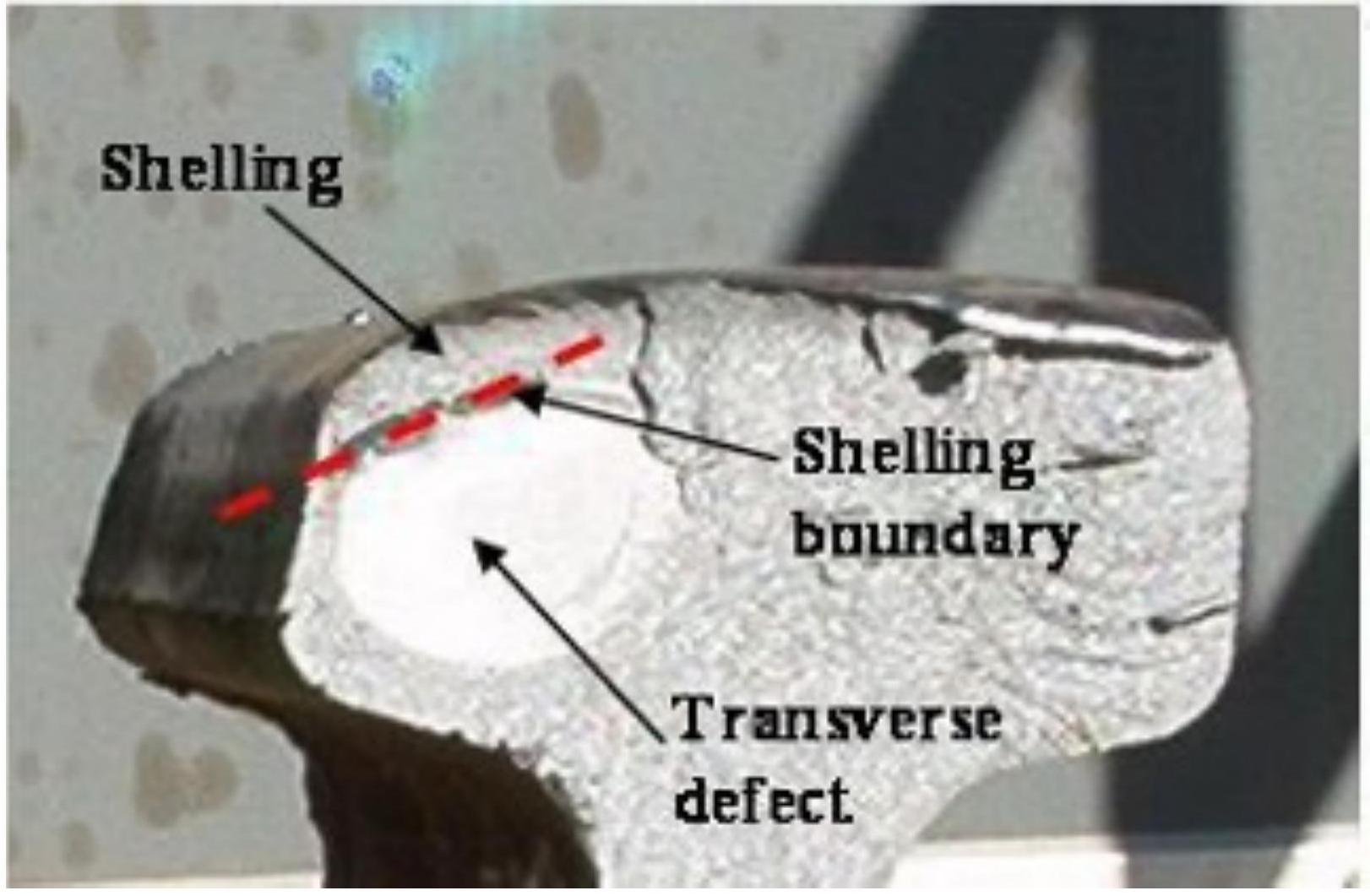
The transverse fissure, also called kidney fracture or silver oval spot (tache ovale), constitutes the most serious manufacturing defect. It is caused by the existence of internal heterogeneity due to various factors: the presence of gaseous bubbles generated when steel cooling is excessively rapid, preventing orderly hydrogen elimination and forming gas bubbles; the presence of non-metallic solid inclusions; and internal stresses developing during rail cooling, since when the material interior is at high temperatures, metal in a plastic state offers very weak tensile resistance.
Once a fissure of this type starts, its propagation is rapid and almost inevitable, especially in the rail head zone where shearing stresses reach particularly large magnitude variations. Fissure propagation occurs via the formation of concentric growth rings or layers. During repeated passage of loads, internal fissure surfaces are compressed and decompressed alternately, causing mutual polishing of these surfaces, granting the characteristic silver appearance visually identifying this defect type.
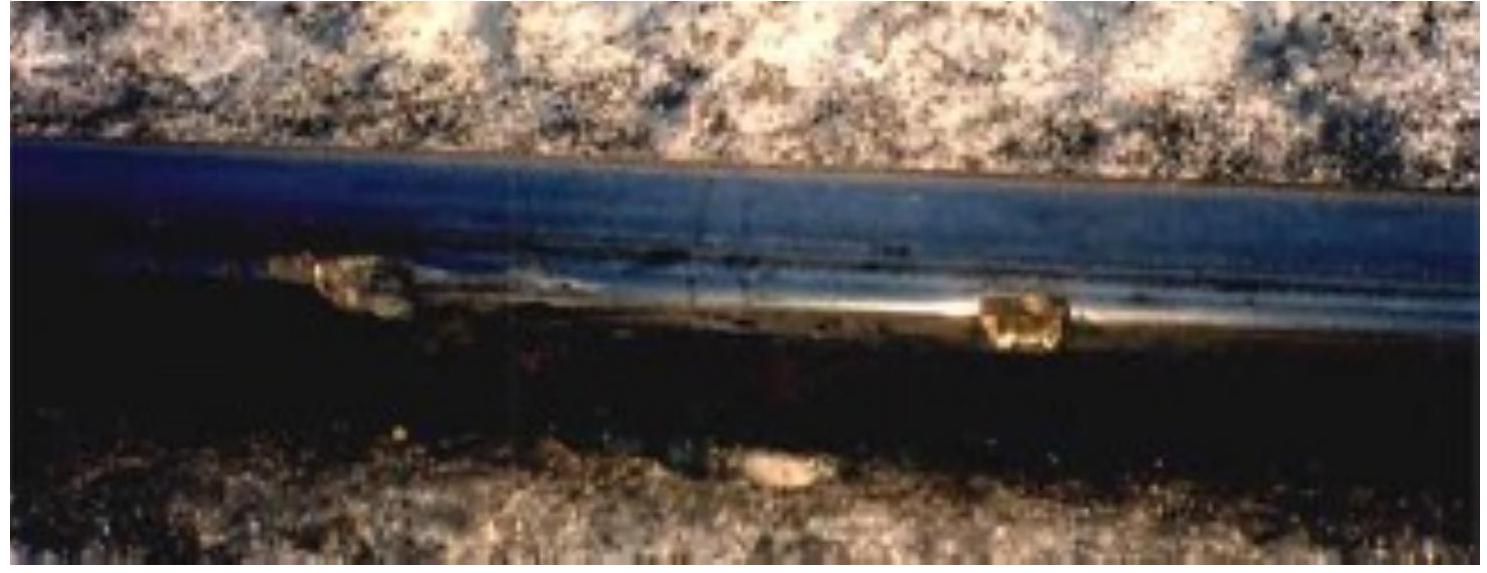
Shelling constitutes a defect analogous in nature but different in localization and manifestation. It occurs on the running table of rails forming the outer thread of horizontal curves, where the rail head flakes or even partially breaks. This defect occurs mainly in curves where, to mitigate excessive wear, rail lubricators have been installed in excessive quantity. This situation creates a zone of permanent maximum stress concentration never redistributed by wear, resulting in localized fatigue and material detachment.
Defects originating from service:
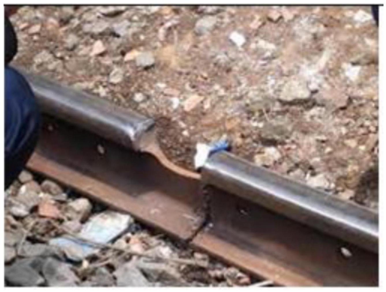
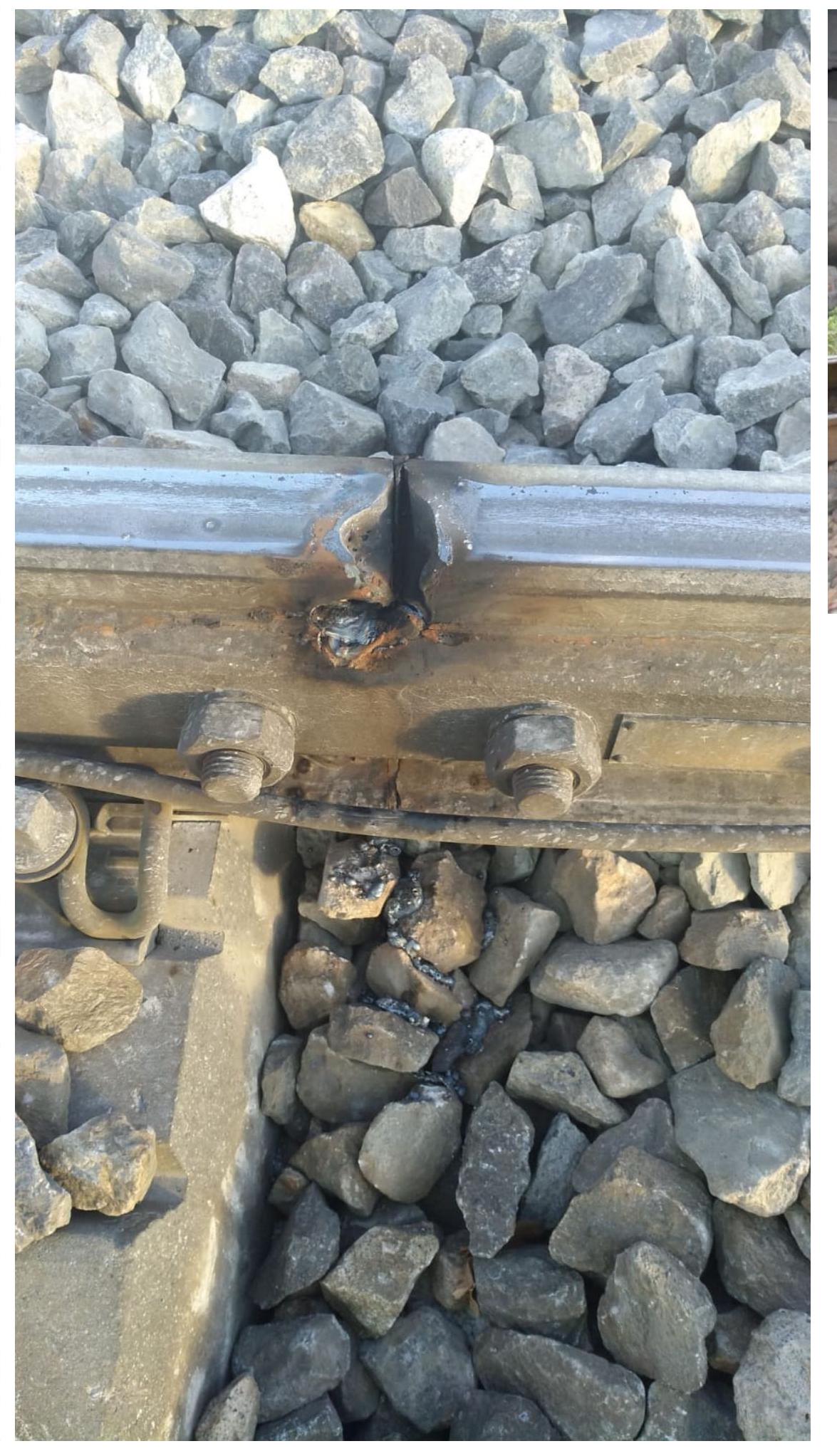
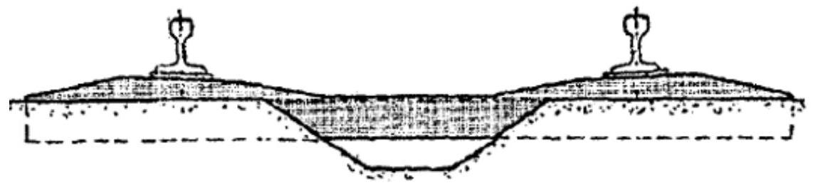
Impacts and bending produced at rail joints constitute a significant source of defects during service. At rail ends, where geometric discontinuity exists due to the joint presence, the passage of rolling stock axles produces progressive crushing of the head surface. This crushing generates a running table unevenness progressing rapidly as traffic increases. Localized deformation progressively increases the “dip” in the joint zone, crushing of joint bar support edges occurs. Furthermore, joint bar fastening bolts maintain repetitive contact with the immediate vicinity of rail holes, locally hardening and embrittling the steel material.
This cascade of progressive deteriorations creates increasingly greater mechanical play in the joint-rail connection. Increased play increases material cyclic fatigue and provokes crack nucleation and propagation, particularly in joint bar holes and also in geometric agreement zones between foot and head.
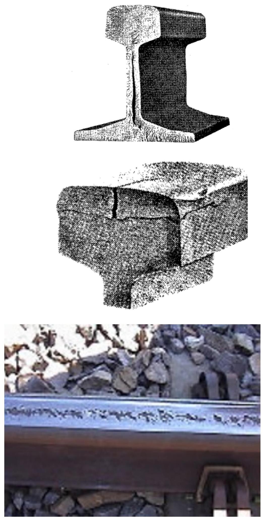
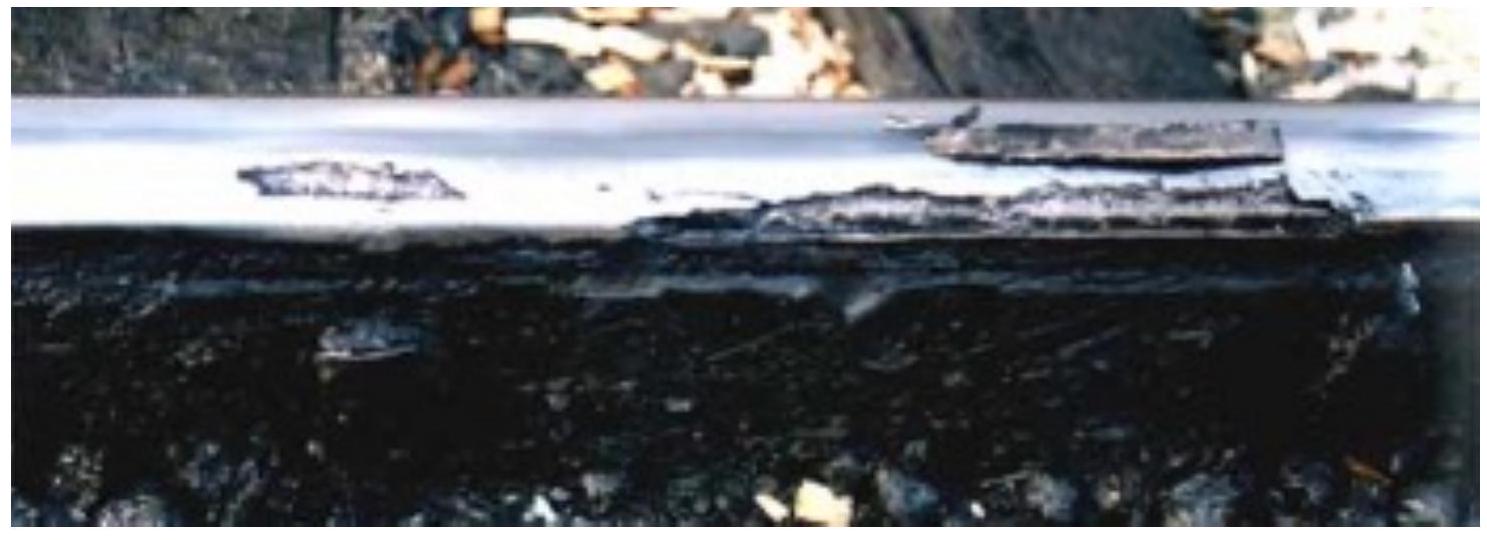
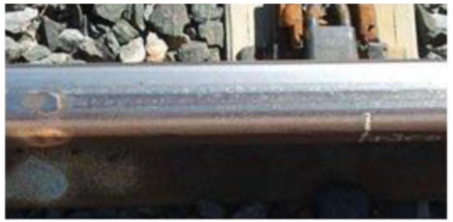
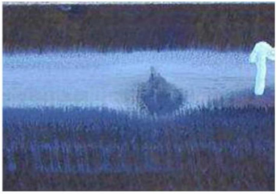
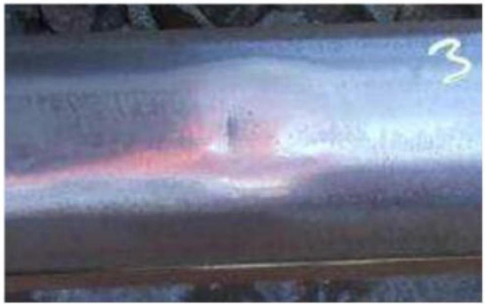
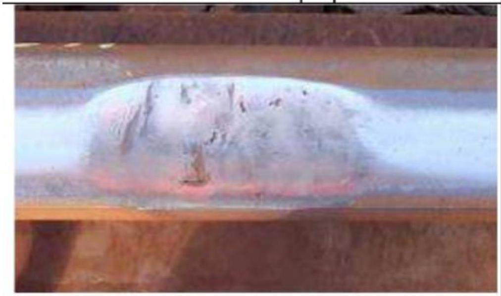
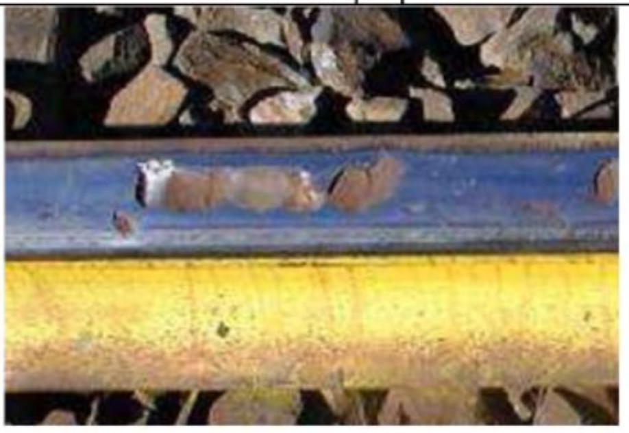
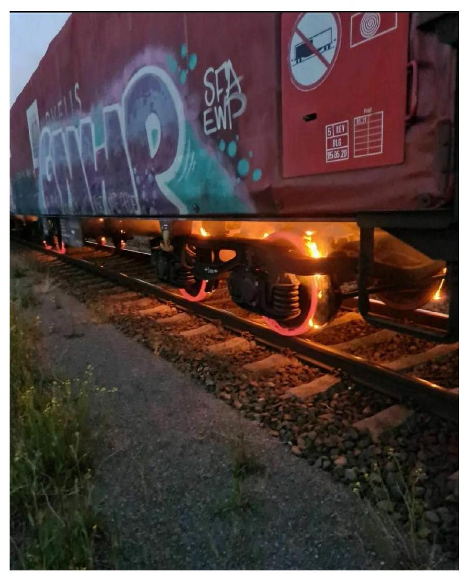
Surface self-tempering (wheel burn) constitutes a metallurgical degradation phenomenon produced by wheel slippage or locking during braking operations. During this phenomenon, rail steel heats up by friction to temperatures exceeding the critical phase transformation point, suffers rapid stretching by compression, and cools abruptly by convection towards the adjacent cooler steel mass. This thermal cycle produces local tempering in the affected zone, originating brittle surface crack formation on the running path, creating a very characteristic appearance called “snake skin”. These surface cracks can propagate progressively towards the material interior, compromising its structural integrity.
This damage typically presents in start-up zones of very heavy trains, frequently located immediately before railway signals where acceleration begins. It can generate local unevenness in the rail head up to 4 millimeters deep distributed over a length of several centimeters. When this magnitude of deterioration is reached, replacing the rail becomes necessary.
Running surface crushing constitutes another important service defect, although with distinct characteristics from self-tempering. Repeated load passage over the rail acts as a cold rolling process: it compacts the crystal grain, similar to any forging operation, hardens the rail surface on the running table, and produces surface fatigue cracks.
However, these cracks do not propagate rapidly towards the rail interior, making it comparatively less dangerous than self-tempering. Likewise, it does not generate the deep superficial crystal structure alteration characteristic of self-tempering.
010501 Mild running surface crushing [10]
010503 Severe running surface crushing [40]
010502 Moderate running surface crushing [40]
010504 Very severe running surface crushing with detachments [40]
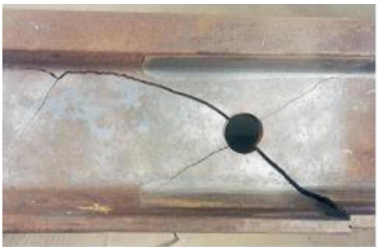
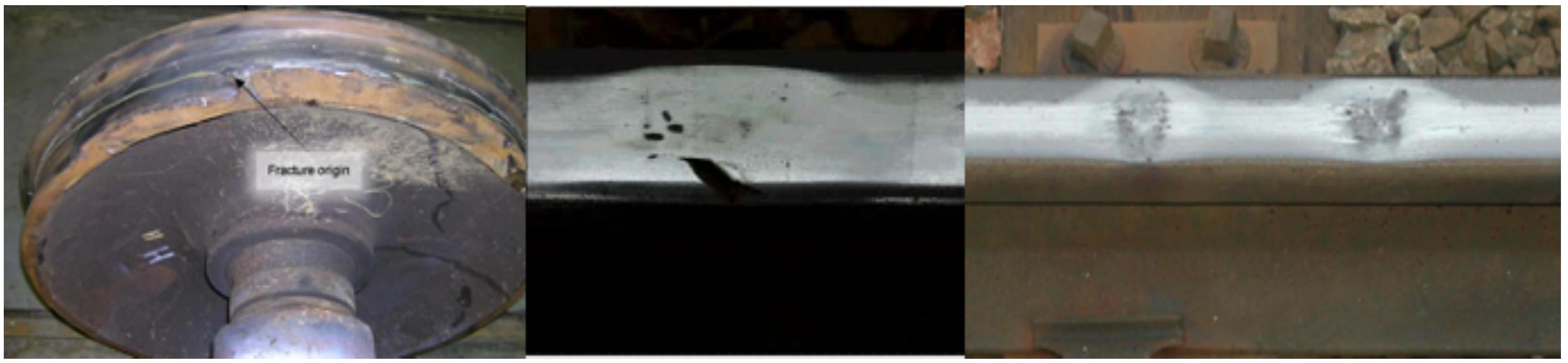
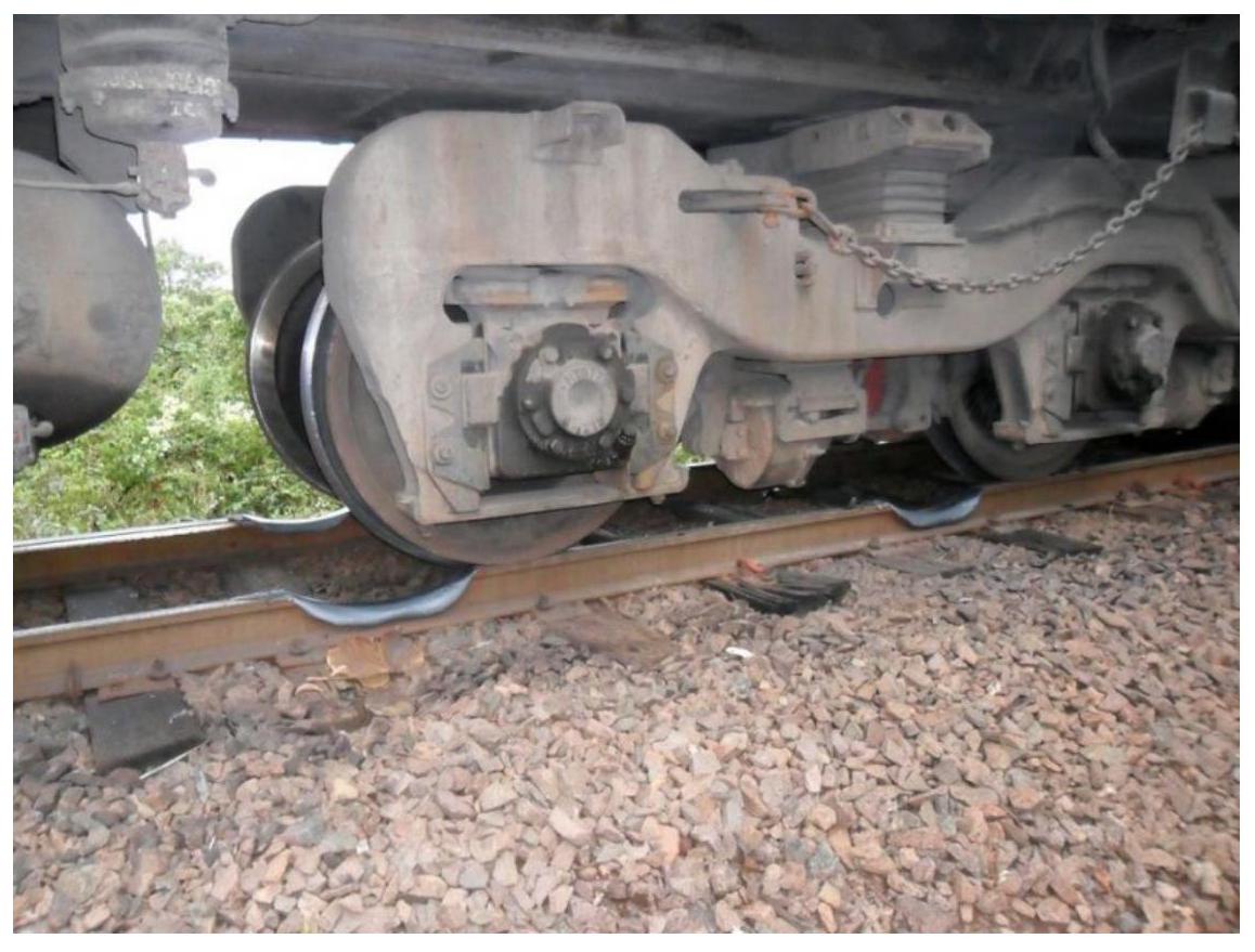
Breaks due to wheel flats constitute a significant cause of accelerated damage in rails. Rolling stock conservation regulations establish tolerance thresholds for these flats: up to 3 millimeters of sag are allowed in freight wagons, while in passenger cars it is limited to 1 millimeter. An illustrative historical case occurred on January 30, 1947, on the Montpellier-Nimes line, where a car with a wheel presenting a flat of 20 millimeters sag in an 18-centimeter chord caused 267 simultaneous rail breaks. This incident occurred at a temperature of -10°C, a condition under which hard steel brittleness increases dramatically, multiplying impact severity.
II.11. Rail wear
Rail wear is designated as the progressive change of profile dimensions, characterized by the gradual removal of material in the head profile via the erosive action of moving vehicle wheels.
During rolling on rails, rolling stock wheels generate a multiplicity of simultaneous mechanical stresses on the rail: compressions normal to the running plane, longitudinal tractions, bending, torsion, and repeated impacts in very high numbers. In the local contact zone between wheel and rail, the material’s elastic limit is exceeded, producing progressive plastic deformations. Of particular importance are lateral stresses exerted by wheel flanges against rail guide faces.
The set of these stresses produces progressive erosion of both the running surface and the internal lateral face of the rail head, generating wear that can vary in speed depending significantly on specific conditions in which railway service develops: track layout geometry (straight line versus curves), track structure typology and stiffness, circulation speeds, load magnitude, presence of wheel slips, among other determining factors.
Rail wear can be divided into two main categories: normal or ordinary wear, occurring as regular service consequence, and corrugation (undulatory wear), corresponding to a particular accumulated fatigue phenomenon.
II.11.1. Normal or Ordinary Wear
Vertical wear constitutes the most common modality, producing progressive loss of rail head height. This wear results from two complementary mechanisms: physical abrasion caused by contact with wheels, and more significantly, chemical corrosion of steel. Corrosion is particularly important because, by eliminating the protective oxide layer naturally forming in traffic absence, it continuously exposes fresh metal to atmospheric corrosive agents. As a reference order of magnitude, it can be established that the passage of one hundred thousand trains produces approximately one millimeter of head height loss.
Track maintenance regulations, such as NAV 7-6-0.1 of Instructions for Track Repairs, establish precise rail disablement criteria. It is considered that a rail seated in track with the standard configuration of 1,667 sleepers per kilometer is technically useless when:
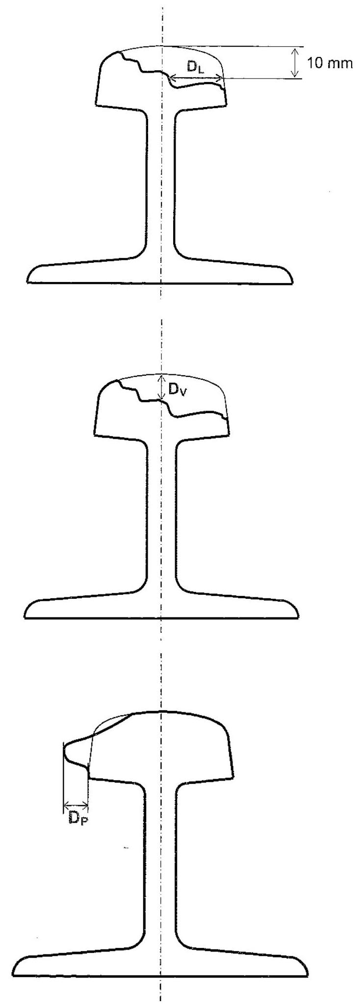
Total accumulated wear exceeds 21 millimeters in RN-45 model rails, 24 millimeters in UIC-54, or 27 millimeters in UIC-60.
Lateral wear exceeds 8 millimeters in RN-45, 10 millimeters in UIC-54, or 12 millimeters in UIC-60.
Lateral wear reaches the lower edge of the head, leaving the rail without effective guide material.
Lateral wear presents a pronounced rounding on its lower edge in the formed chamfer, indicating deep cutting.
Lateral wear is such that it allows wheel flanges to rub directly against joint bars, eliminating lateral protection.
Web wear exceeds 4 millimeters in RN-45 rails, 7 millimeters in UIC-54, or 7.5 millimeters in UIC-60.
There is a reuse practice allowing extension of service life for rails with lateral wear. Rails presenting lateral wear as described can be reused by inverting rail position, using the unworn side of its head as the new active running flank. When these rails are welded, it is critical to verify alignment quality of welds on the “non-active” flank before inverting it to “active” state, performing corresponding rectification grinding when technically feasible. Wear exceeding specified limits supposes definitive rail disablement, since inversion is not viable.
II.11.2. Corrugation (Undulatory Wear)
Months or years after initial placement of new rails on track, characteristic surface defects sometimes appear with regularly spaced wavelength. These manifestations of corrugation can present in three variants according to their wavelength:
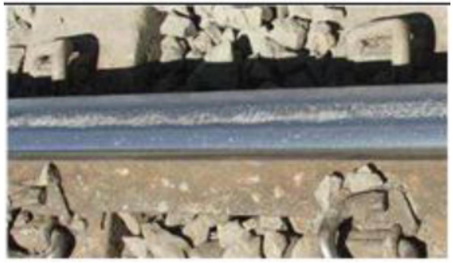
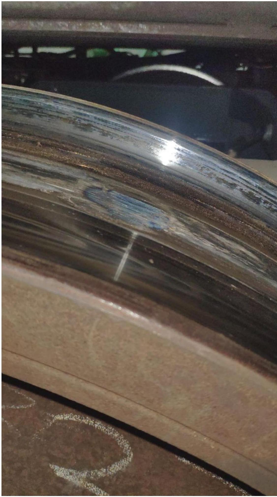
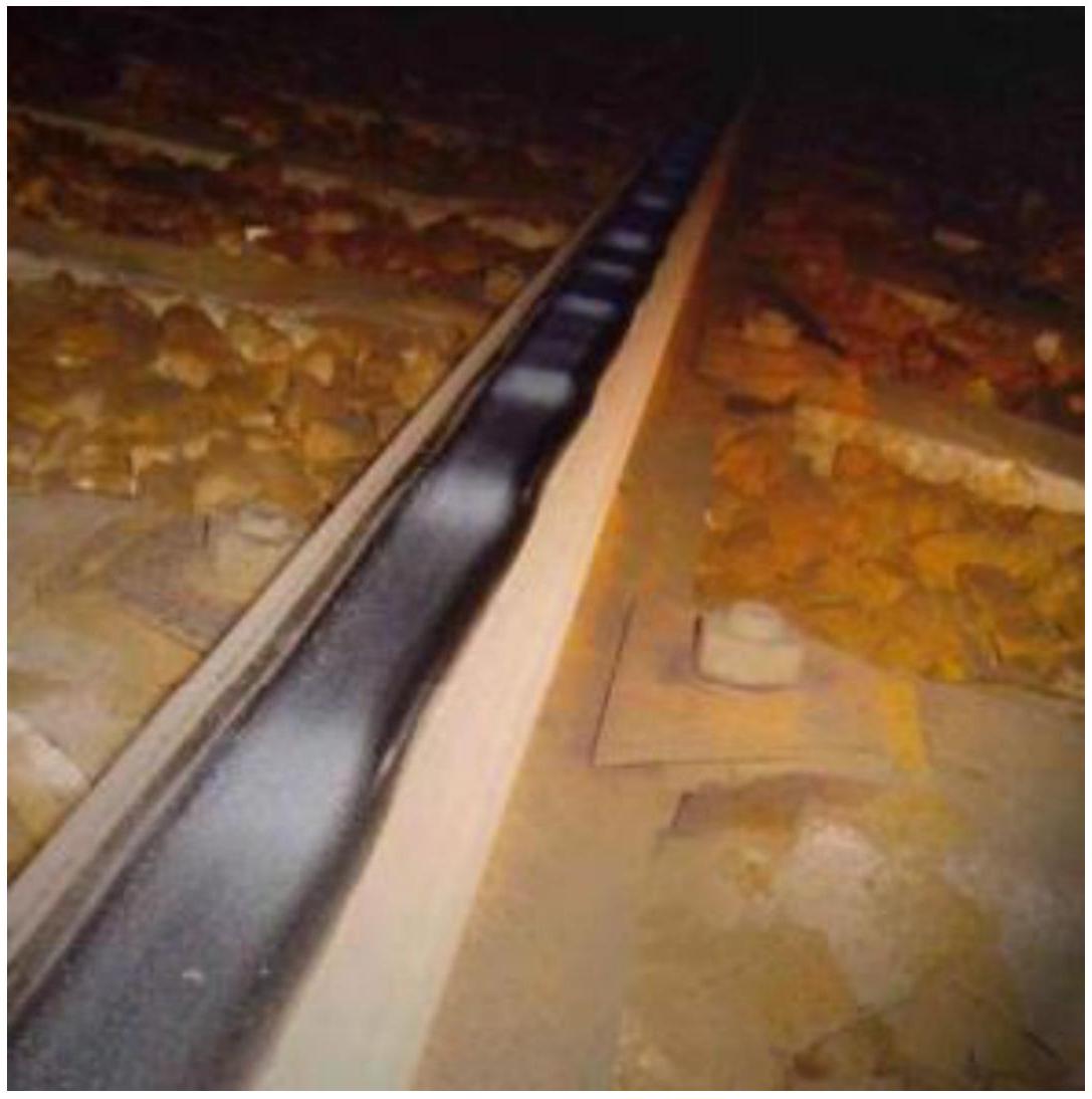
Short-wave wear (roaring rails) presents a typical wavelength of 60 millimeters, corresponding to undulation nodes. At these points, the rail has suffered localized surface tempering. The running path shows a series of shiny spots corresponding to these zones. The depth of “valleys” or depressions between nodes, although visually specific from 4 or 5 hundredths of a millimeter, can reach values of 2 or 3 tenths of a millimeter in advanced cases.
Medium-wave wear is an intermediate condition between short-wave and long-wave extremes.
Long-wave wear presents wavelengths in the range of 60 centimeters to 2 meters. It is difficult to observe in simple visual inspections since the rail does not present a tempered zone that has suffered cementation observable to the naked eye.
Short-wave corrugation is of greatest practical incidence on current railway lines. It generates vibrations in the track superstructure and simultaneously in vehicles circulating on it, harming both elements and significantly increasing maintenance costs. As circulation speed increases, dynamic loads derived from undulations increase, being able to equal static loads in magnitude under certain circumstances. Although generated stresses are damped relatively quickly in sleepers, they produce very severe deteriorating consequences on sleepers themselves and on the rail than on general track leveling problems.
Medium-wave wear generally appears in curves with radius less than 500 meters, particularly on the low thread of the curve. It mainly affects lines where vehicles with very high axle loads circulate.
It can be solidly affirmed that the existence of corrugation in the rail appreciably reduces the complete service life of the track superstructure and rolling stock, significantly increases noise levels, markedly decreases comfort perceived by passengers, increases traction force necessary to tow rolling stock, multiplies conservations costs of the integrated wheel-rail system, and reduces the operational safety factor of circulations.
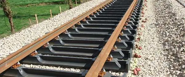
Chapter III The Sleeper
Sleepers constitute essential structural elements arranged in a transverse direction perpendicular to the track longitudinal axis. They function as support elements on which rails are placed, and critically, act as a connecting link between rail and ballast via specialized fastening systems. Together with rails, sleepers form the structural frame or grid of the railway track.
III.1. Functions
Sleepers fulfill multiple and critical functions for correct railway infrastructure functioning. Their primary function is to transmit and distribute loads derived from rolling stock from rails to the ballast, distributing these forces over a wide surface to minimize contact pressures.
A second fundamental function is to secure and maintain the required track gauge, transversely bracing the two rails to prevent their approach or separation. This function is critical for operational safety.
A third important function in Vignole rails is to provide necessary rail inclination (typically 1/20 towards the curve interior in curved lines). This inclination is mandatory in railway systems utilizing truncated cone tires on their wheels, inclination compensating natural vehicle overturning tendency derived from tire geometry. This function can be performed via two methodologies: adzing (direct recess in sleeper) or via specially manufactured baseplates.
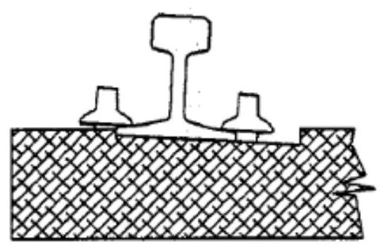 Inclined adzing
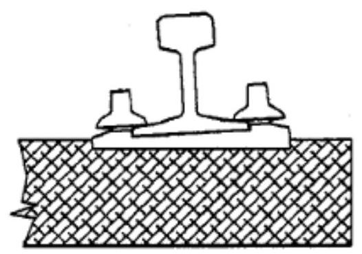 Baseplate
Beyond these specific functions, the sleeper must maintain general track stability in all its directions: both in the horizontal plane (considering longitudinal and transverse displacements) and in the vertical plane. This stability must be effective against static stresses proceeding from structure own weight and thermal variations producing expansions and contractions, as well as against dynamic stresses derived from passing loaded trains at speed. On railway lines equipped with signaling circuits, the sleeper must fulfill an additional function: electrical insulation of the two rail threads to allow functioning of track occupancy detection systems and traffic control systems.
Regarding track geometric stability, sleeper dimensions to consider are multidimensional:
- Stability in vertical plane: determined fundamentally by sleeper length and width.
- Stability in lateral plane: determined by sleeper width, height, and weight.
- Stability in longitudinal plane: determined by the three main dimensions and total sleeper weight.
Since origins of modern railway in 19th century, after a brief initial period in which natural stone blocks were used as rail support elements, wood imposed itself as predominant material for sleeper construction. Wood species employed historically include oak, beech, pine, fir, birch, cedar, eucalyptus, and a variety of tropical woods especially apt for this railway use. Wood demonstrated possessing ideal properties for this application.
Only in periods of critical wood shortage in certain regions or specific eras, were railways driven to experiment with alternative substitute materials, such as steel and reinforced concrete. Throughout the 20th century, concrete sleepers gradually evolved in technical sophistication, culminating in current prestressed concrete sleepers, offering durability and performance characteristics much superior to early versions.
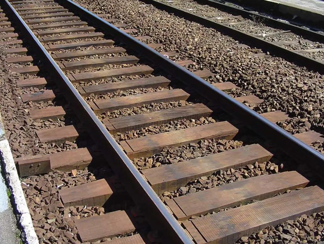
III.2. Wooden sleepers
Wooden sleepers enjoyed great acceptance since the very origins of commercial railway, founded on their extraordinarily favorable characteristics: elevated elasticity allowing effective impact absorption, excellent nail-holding ability facilitating rail fastening via spikes or screws, relative ease of conservation and repair via simple carpentry works, high electrical insulation making them ideal for lines with track signaling systems, and their general abundance on the planet with good geographic distribution.
Additionally, wooden sleepers present great resistance to all kinds of stresses. When solicited locally, as in derailment events, they do not break in a brittle manner but develop progressive notches. They offer good resistance to sliding on ballast via slight encrustation of ballast material in their surface. They possess relatively reduced weight facilitating manual handling and significantly reducing transport costs. They can be reused in secondary or service tracks via mechanical recovery treatment. Their manufacturing process is economic and relatively simple. They present structural toughness without being brittle, good resistance to weather and atmospheric agents, and admit small bending deformations at their midpoint without catastrophic fracture.
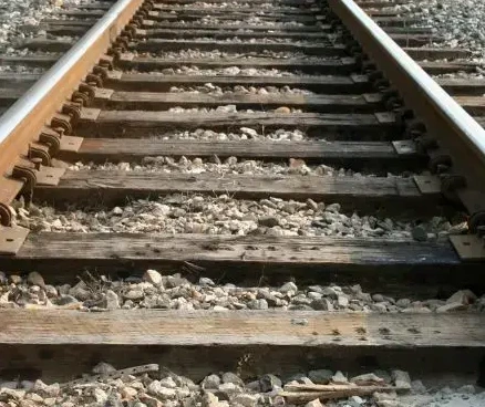
However, wooden sleepers also present significant disadvantages: progressive aging during service with substantial changes in their primitive characteristics of elasticity and resistance, limiting their typical service life to 20-25 years. They are susceptible to combustion in case of fire. They degrade by attacks from microorganisms, fungi, woodworms, and termites, especially in humid or tropical climates. Fastenings weaken progressively over time. They possess relatively low weight (70-80 kilograms), which although facilitating handling, results insufficient to provide necessary stability on very intense traffic lines.
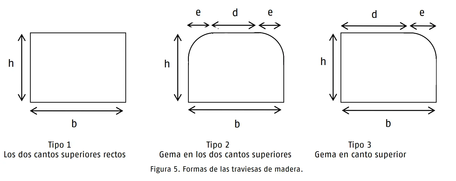
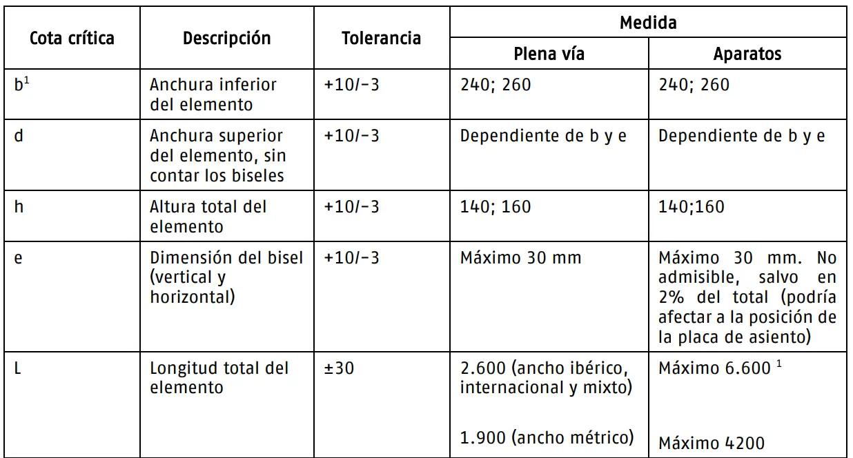
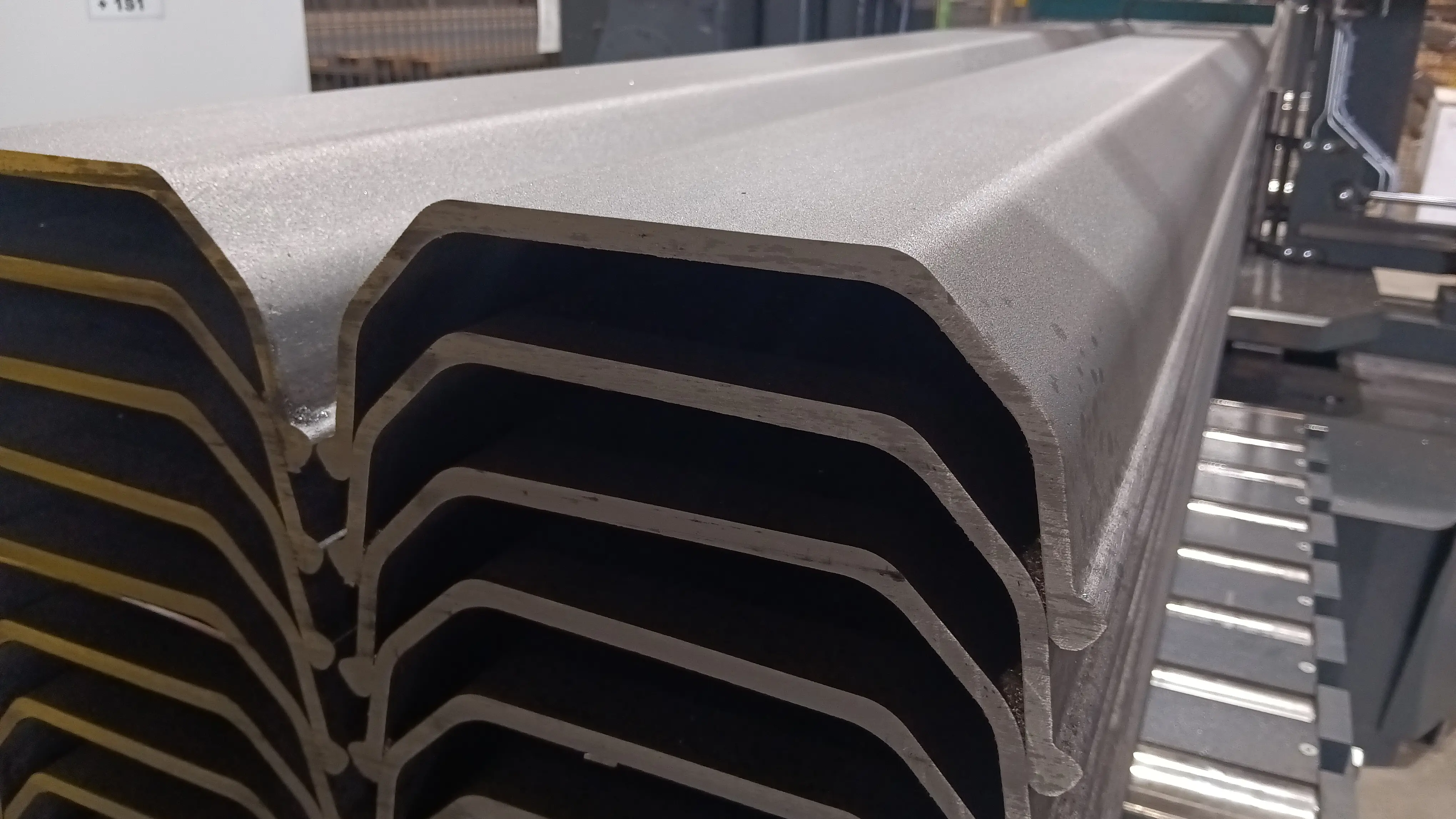
Diverse geometric configurations of wooden sleeper cross-section are standardized in general lines by UIC, requiring the lower face to be completely flat, lateral faces sensibly perpendicular to this base, and upper face presenting horizontal flat zones in specific locations destined to support rails or to allow inclined adzing. The resulting shape is approximately parallelepipedal.
UIC Technical Specification establishes specific dimensional parameters: lower face width must be between 0.26 m and 0.22 m, height between 0.16 m and 0.13 m, and upper face support zones between 0.20 m and 0.13 m.
 Adif wooden sleepers ET 03.360.540.3
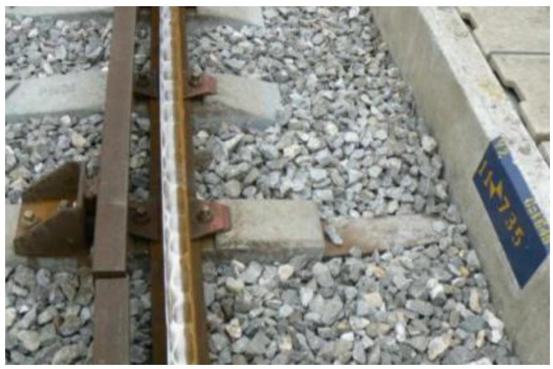
III.3. Metal sleepers
The metal sleeper constitutes a manufactured industrial product via relatively simple rolling processes. Its structure is based on a rolled profile in inverted U shape, complemented with special flanges at its ends forming structures similar to hoes. These flanges are designed specifically to allow the sleeper to drive into the ballast, opposing effectively transverse track displacement, thus achieving highly effective embedding in ballast material.
The rail is fixed to the sleeper via specialized clips resting on the rail foot edge. Clips are held using nuts screwed onto through bolts. The combination of two or three distinct type of clips of different dimensions allows achieving gauge widening adjustments demanded by different track configurations. It is possible to adapt complementary elastic devices to improve damping capacity.
The metal sleeper is relatively light (approximately 80 kilograms) and easy to place on track. However, this low weight characteristic, which could be considered advantageous from handling point of view, results negative in very heavy circulation and high speed tracks. The metal sleeper is inherently noisy during passage of circulations. Additionally, it is electrically conductive, presenting the inconvenience of not allowing electrical insulation of two rail threads, unless special insulation devices are installed with consequent investment cost increase.
Metal sleepers can be manufactured in both steel and cast iron. Cast iron sleepers vary better regarding corrosion and are simpler to manufacture industrially. However, rolled steel sleepers are more widely used because rolling turns out economically more advantageous than casting process.
In Western Europe, the metal sleeper did not reach generalized acceptance, due fundamentally to available forest resources being abundant. Nevertheless, in desert or semi-desert zones, particularly in North Africa, Southern Asia, and India, use of metal sleepers was very important. The old Central of Aragon railway in Spain was a notable example of metal sleeper utilization, where they still persist on secondary tracks. They are also found in networks of Switzerland, Austria, and Germany. Due to their very effective embedding capacity in ballast, they have frequently been used in special railways like funiculars and rack railways (such as Nuria railway), where they offer superior elastic retention.
Metal sleepers present serious corrosion problems by oxidation in high relative humidity zones: tunnels, deep trenches, swampy or poorly drained terrains. They are especially vulnerable to chemical attack from saline air in maritime coast proximities, sulfur vapors from blast furnace slag ballast, or acidic vapors emitted by nearby chemical product factories.
In lines equipped with electric traction, they present the serious inconvenience of causing direct grounding (“frank earth”), which can result in stray current circulation dispersed through ground and in electrolysis phenomena of steel and other buried metals, with subsequent dangers for both structures and operational safety.
The main advantage of metal sleepers is that of considerable temporal durability. Since their structural weak point are rail fastening connections, their operational life depends more on number of load cycles (circulations) than on their calendar age. In principle they turn out more advantageous on weak or moderate traffic lines, where wooden sleepers rot or significantly loose their mechanical characteristics before having completed their direct mechanical wear by compression.
 steel sleepers
III.4. Concrete sleepers
Depletion of forests in a series of countries and derived wood cost growth, as well as wide consumption of wood as raw material in industrial branches, such as chemical, cellulose and paper, furniture, etc., where its use is more adequate, from economic point of view, maintained permanent interest towards results of trials with concrete sleepers.
Tests with reinforced concrete sleepers reached considerable development during First World War, due to supply problems, but results were unsatisfactory.
For same reasons, interest re-develops during Second World War, but now with backing that prestressed concrete technique supposes for reinforced concrete.
At beginning of their utilization, they imitated wooden sleeper shape, i.e., were parallelepipedal. Problem: with load passage, aggravated by sleeper great rigidity, ballast rarefaction occurs and, conversely, concentration thereof in sleeper center. Over time phenomenon accentuates much, sleeper ends settle more than their central part and in this part great negative bending moment arises, supposing concrete works in tension in sleeper central part: cracking.
To avoid this situation various solutions were devised:
- Reinforce reinforcements.
- Acted not on sleeper, but on ballast, practicing longitudinal furrow in track central part, to avoid sleeper resting in that zone.
- Symmetric solution was also attempted, i.e., create furrow in sleeper thinning its edge in central part.
- Symmetric solution was also attempted, i.e., create furrow in sleeper thinning its edge in central part.
- Thin central part of sleeper, not its edge, but its width, so due to ballast support reaction distribution on sleeper, bending moment in central part decreases.
Advantages of concrete sleepers are:
- Elevated service life: can be estimated two to three times corresponding to wooden sleeper (treated).
- Permanence of their elastic characteristics: due to very important homogeneity in physical state of material constituting them throughout entire period of their utilization, we have great homogeneity of elastic characteristics of support under rail.
- Elevated track stability: due to their great weight, which can be 300 kp against 80 kp of wood. This stability in longitudinal sense, helps utilization of long welded rail. And in transverse sense, decreases buckling risk.
- Adaptability of their design: of their shape to most convenient to support service stresses.
Inconveniences regarding wooden sleeper:
- They are more expensive.
- Conduct electric current better, with subsequent problem of insulation of two rail threads when this is necessary due to existence of track circuits.
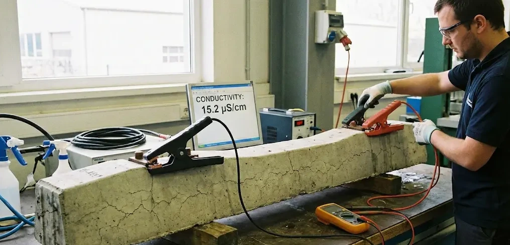 Conductivity Test
III.5. Mixed two-block sleepers
Consists of replacing problematic central part with a metal beam, whose profile is sufficiently rigid to ensure maintenance of track gauge and rail inclination and, at same time, elastic enough to absorb (without danger for concrete pieces in which it is embedded by adherence) torsion or flexion stresses caused by tamping inequality under both heads or by unevenness of one regarding other.
Although simple in construction which motivated their important development, they present inconveniences such as:
- great steel consumption, that of tie bar
- poor track gauge conservation, gauge widening of 10 mm and more, making it inadequate for important speeds (greater than \(140 \mathrm{~km} / \mathrm{h}\) ), due to their small vertical and transverse rigidity;
- tie bar corrosion
- bad behavior in derailments
- tie bar breakage, etc.
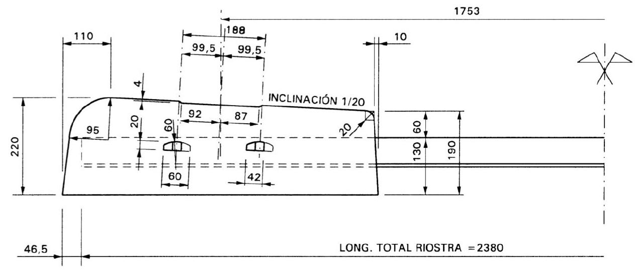
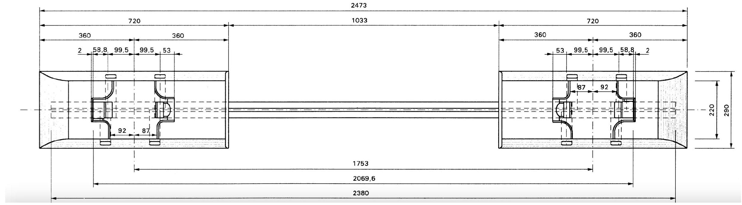
Appear around 1925, and among them are Vagneux sleeper, which is mixed steel and concrete sleeper of semi-rigid type. Central part is metal beam, of I-beam profile, embedded by adherence in two concrete blocks or heads, 70 cm long by 25 to 35 cm wide.
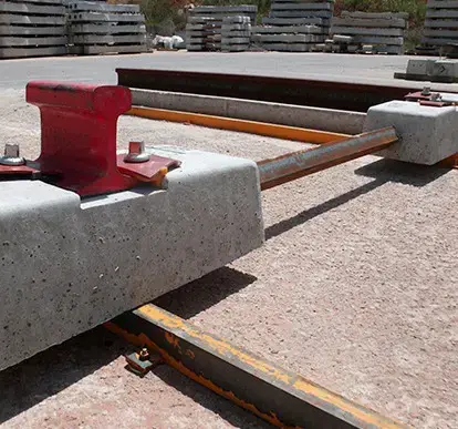
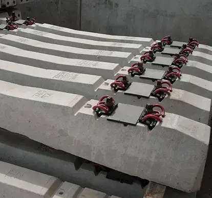
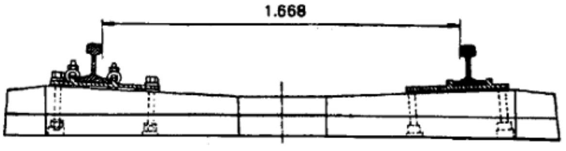
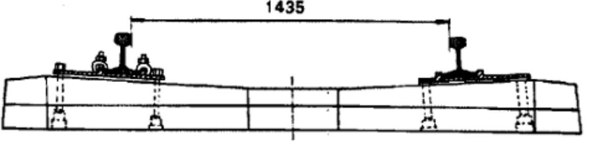
In Spain in 1965 first experiences began in RENFE on two-block sleepers, of reinforced concrete, type R.S. (in image). Subsequently variations were developed: Bi-block sleepers - RENFE (BR-94); Polyvalent bi-block sleepers (PB-91) capable of being installed in both track gauges; Special sleepers, in concrete slab, monovalent Stedef, for RENFE gauge or for international gauge; Special sleepers, in concrete slab, polyvalent Stedef, for broad gauge of 1,668 mm and for international track of 1,435 mm.
 ELEVATION-SEMISECTION
ELEVATION-SEMISECTION
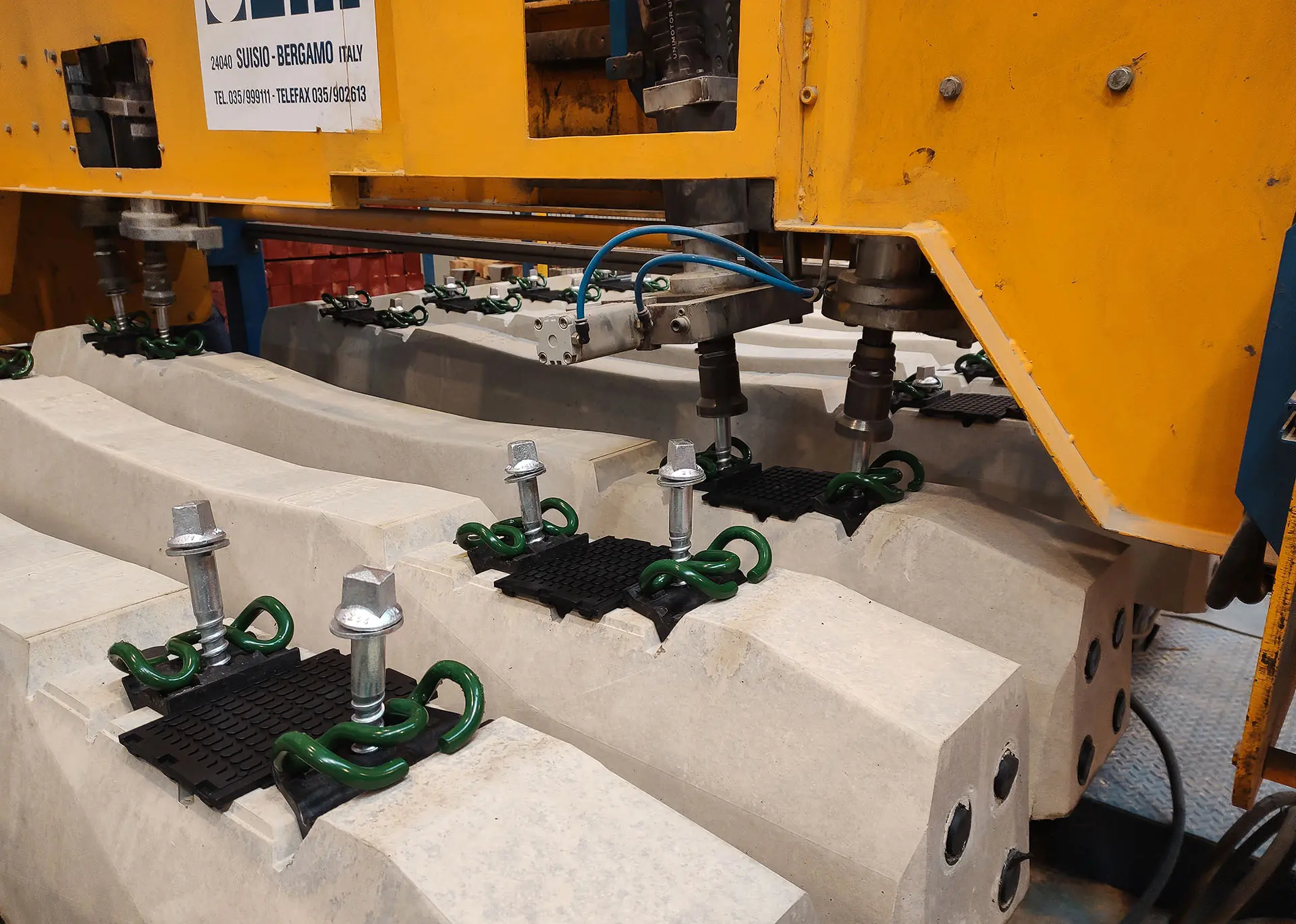
III.8. Prestressed concrete monoblock sleepers
Appear around 1950 and is seductive solution, since it allows:
- Obtain better resistance to alternating stresses, since concrete always works in compression.
- Decreases sleeper thickness (regarding monoblock), particularly in its center, since reinforcements must not, as in ordinary reinforced concrete, be situated as far as possible from neutral fiber. Risk of ballast concentration in central part, which was very serious in reinforced concrete monoblock, is very reduced in this sleeper. Very close position of neutral fiber of reinforcement wires, allows notably lowering sleeper inner face in its central part.
- Decrease necessary steel
III.8.1. Characteristics:
- Approx. weight: 300 Kg
- Excellent longitudinal and transversal track holding
- Favors track geometry conservation (less maintenance)
- Recommended for tunnels and humid environments
- Suitable for large loads and speeds. Ideal for track with LWR (used in High Speed).
- Rigidity:
- Need for greater ballast thickness
- Need for elastic baseplates
In order to solve problems presented by R.S. sleeper, and at same time to satisfy superior needs that infrastructure presents facing forecasts of speed, traffic and comfort, Renfe decided to adopt monoblock sleeper (monobloc) and among existing ones, for technical-economic reasons, German Dywidag (D.W.) sleeper and fastening of Vossloh Werke house, type HM, which is direct and elastic.
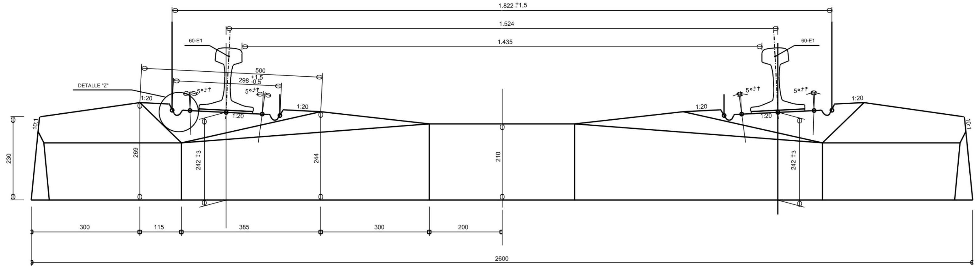
With object of being able to perform track gauge change operation of Spanish network from 1,668 mm to 1,435 mm, a series of polyvalent sleeper designs have been developed, whose main characteristic is allowing fixation of two rail threads in two different positions, remaining in one of them track with national gauge (1,668 mm) and in other with international gauge (1,435 mm).
There also exist three-thread sleepers, allowing Iberian and international track gauge at once (Not polyvalent). Some
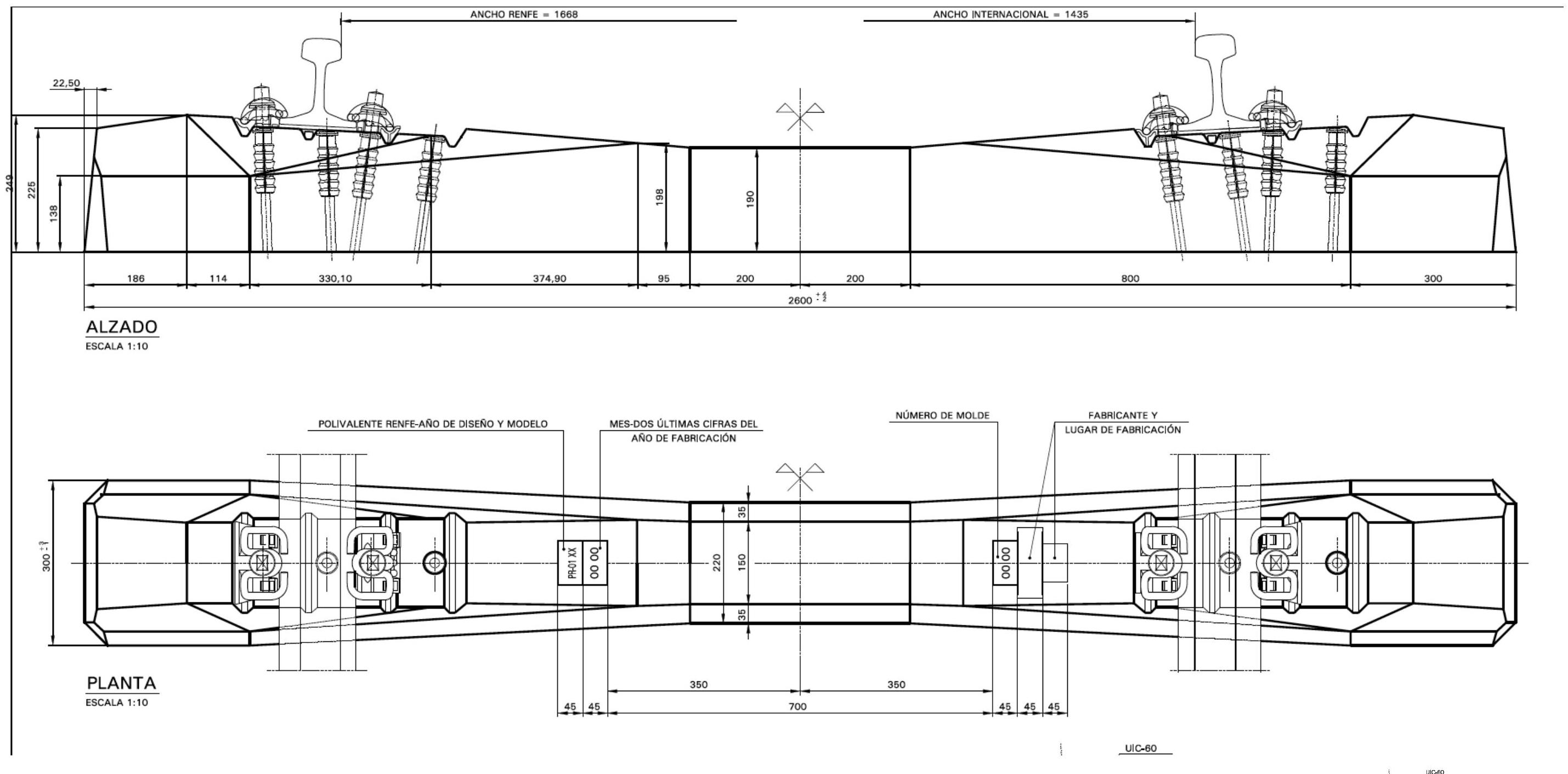
For High Speed in international gauge, sleeper employed is AI 04.
| Sleeper type | Nominal gauge | Rail profile | Other characteristics |
|---|---|---|---|
| MR | 1,668 | 54E1/60E1 | Monovalent and symmetric. Length 2,600 mm |
| PR | 1,435 or 1,668 | 54E1/60E1 | Polyvalent and symmetric. Length 2,600 mm |
| AI | 1,435 | 60E1 | Monovalent and symmetric. Length 2,600 mm |
| AE | 1,435 | 60E1 | Monovalent, symmetric and with optimized geometry facing ballast flight. Length 2,600 mm |
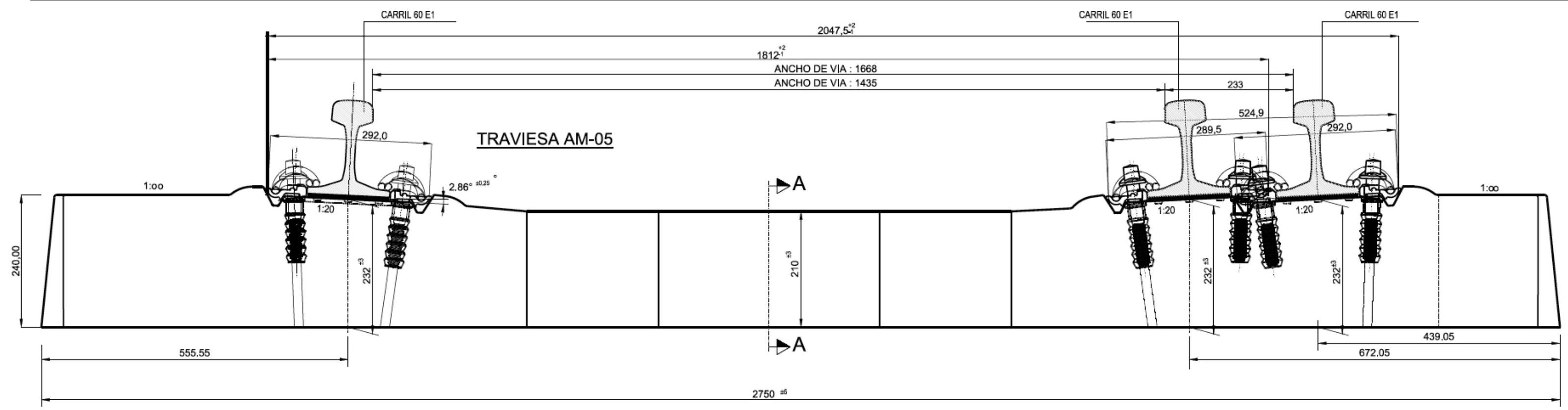
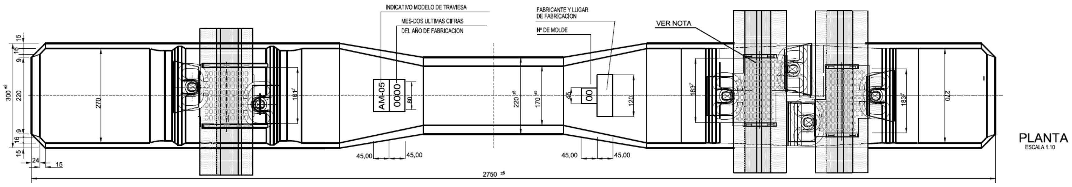
| AM | 1,435 and 1,668 | 54E1/60E1 | Multiple gauge, asymmetric in both gauges and with 3 threads. Length 2,750 mm |
| SR | 1,435 and 1,668 | 54E1/60E1 | Multiple gauge, symmetric in 1668 (allows two positions in 1435) and with 4 threads. Length 2,750 mm |
| SI | 1,435 and 1,668 | 54E1/60E1 | Multiple gauge, symmetric in 1435 (allows two positions in 1668) and with 4 threads. Length 2,750 mm |
| MM | 1,000 | RN45/54E1 | Monovalent and symmetric. Length 1,900 mm |
| Sleeper model | ||||||
|---|---|---|---|---|---|---|
| AI/AE | PR | AM/SR/SI | MR | MM | ||
| Use conditions | Rail profile | 60E1 | 54E1 or 60E1 | 54E1 or 60E1 | 54E1 or 60E1 | RN45 or 54E1 |
| Rail inclination | 1/20 | 1/20 | 1/20 | 1/20 | 1/20 | |
| Fastening system | VM or VE | VO, VM or VE | VM or VE | VO, VM or VE | VO, VM or VE | |
| Nominal gauge (mm) | 1,435 | 1,435 or 1,668 | 1,435 and 1,668 | 1,668 | 1,000 | |
| Design gauge (mm) | 1,437 | 1,437 or 1,668 | 1,437 and 1,668 | - | - | |
| Load per axle (t) / speed (km/h) combination | 25/160 or 22.5/350 | 25/160 or 22.5/350 | 25/160 or 22.5/350 | 22.5/220 | 20/120 |
Note: when rail profile is 54E1, circulations of 25t/axle cannot exceed \(150 \mathrm{~km} / \mathrm{h}\)
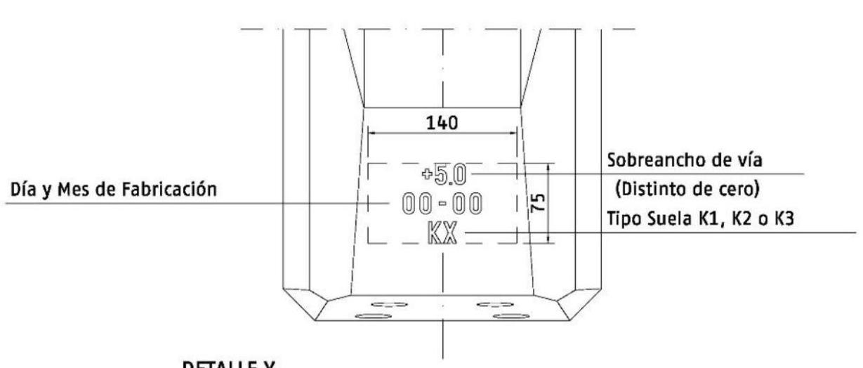
DETAIL Y
 Traviesa AI-04
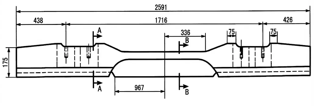
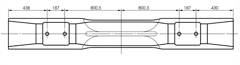
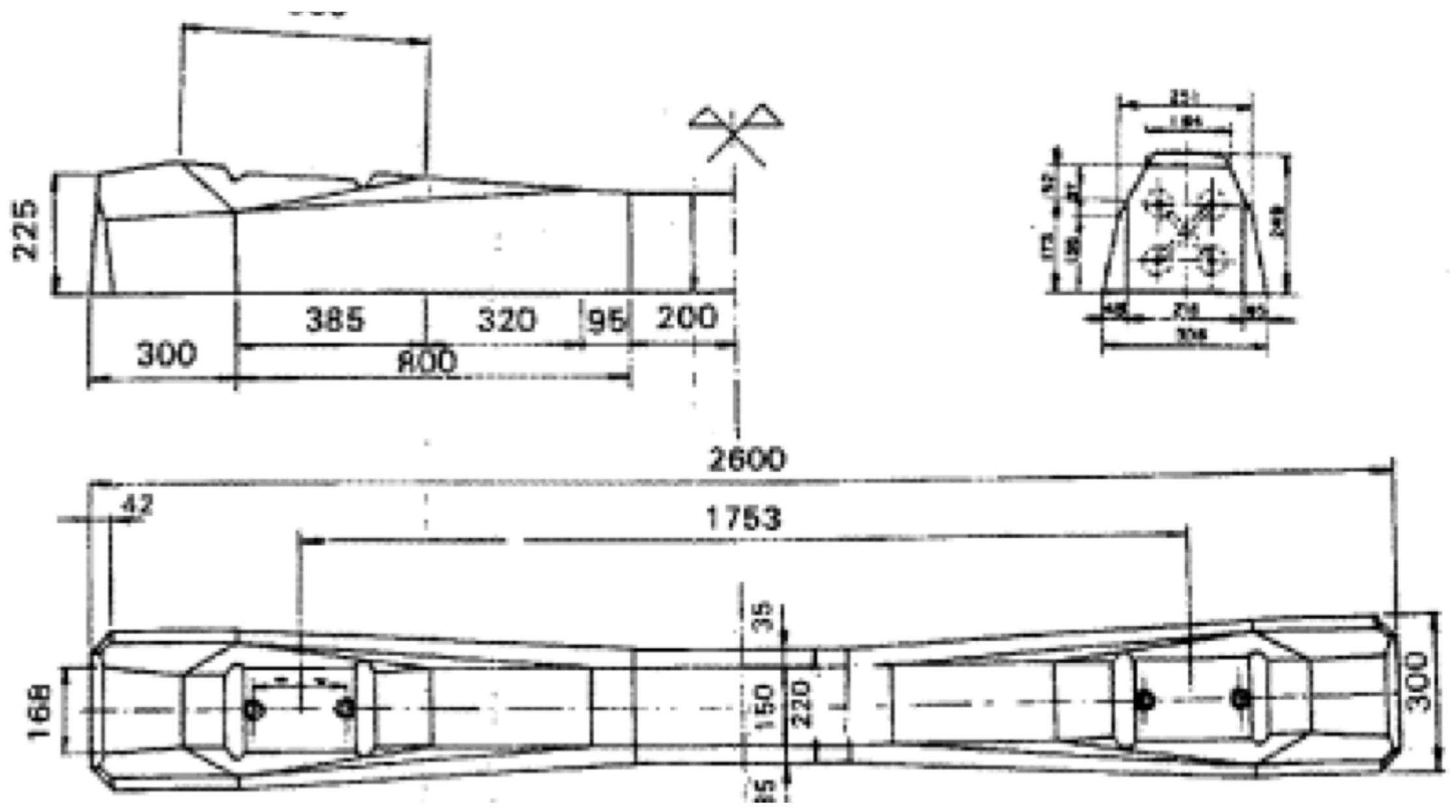
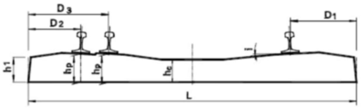
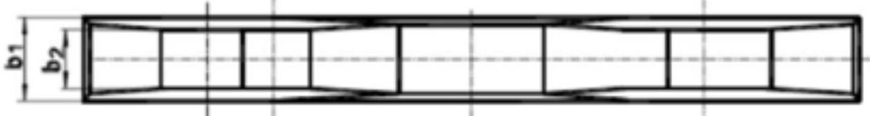
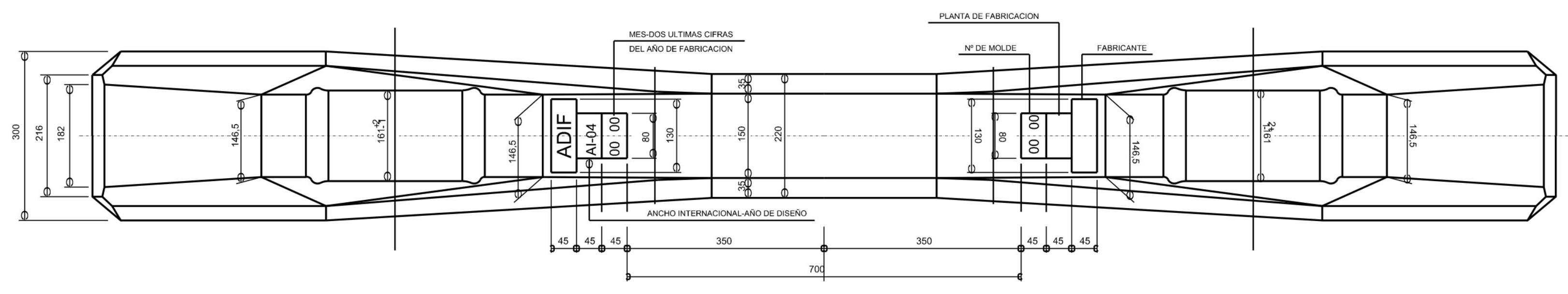
III.8.2. PR-01 Sleeper
Among diverse prestressed monoblock sleeper designs developed to satisfy demands of modern railway infrastructure, PR-01 sleeper represents particularly versatile solution. This polyvalent prestressed concrete sleeper was conceived to allow operation in two distinct track gauges: Iberian gauge of 1,668 mm and international gauge of 1,435 mm. Fundamental characteristic defining this sleeper is its capacity to maintain fixation of both rails in alternative positions, which facilitates significantly track gauge conversion operations in railway networks requiring compatibility with both standards.
PR-01 sleeper geometry has been optimized to provide symmetry facilitating its orientation in travel direction, thus reducing installation errors. Internal structure of prestressing wires follows carefully calculated pattern to distribute uniformly compressive tensions in concrete interior, guaranteeing consistent behavior independently of chosen mounting position. Anchor design allows accommodating direct and elastic fastening systems, facilitating secure rail fixation in any of the two gauge positions.
REFE GAUGE MOUNTING DETAIL
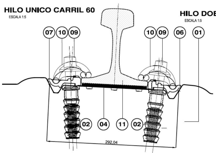 DOUBLE 60 RAIL THREAD
SCALE 1:5 E 60 RAIL
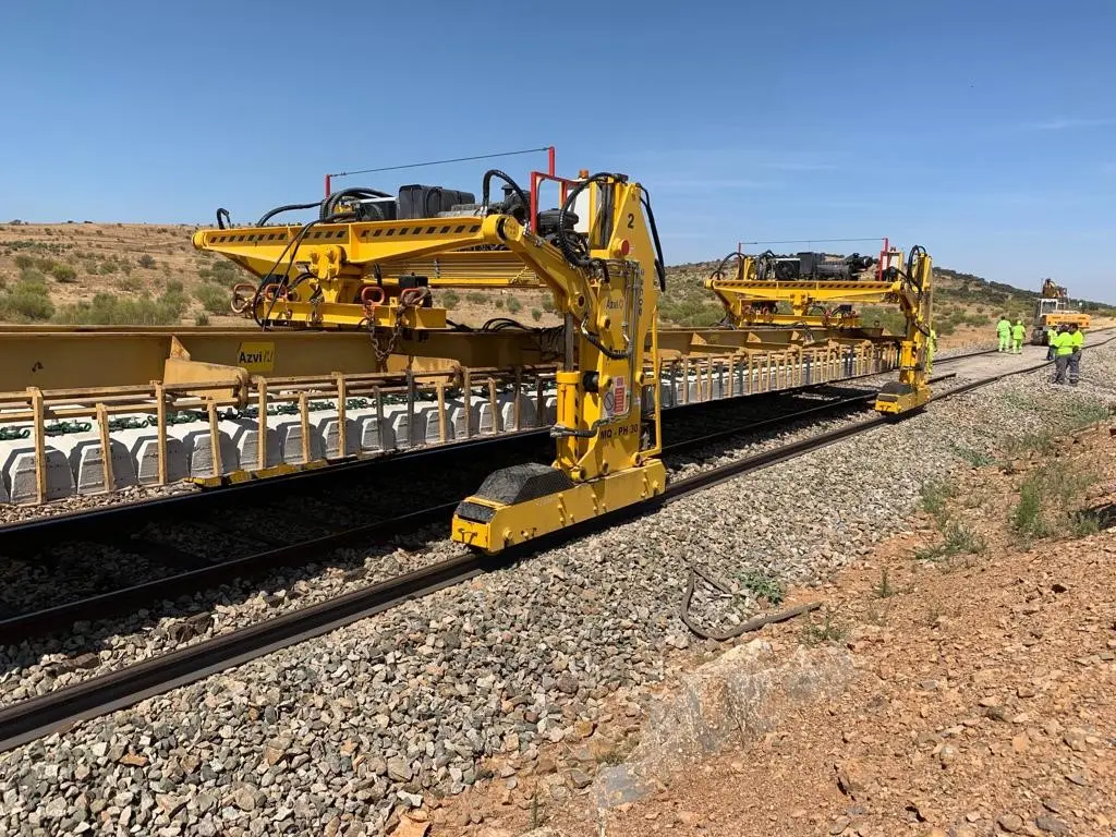
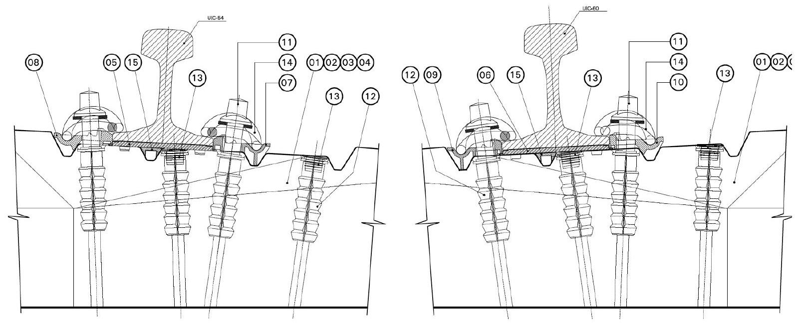
III.9. Rail + sleeper
Integral understanding of track behavior requires analyzing not only individual components—rails and sleepers—but also dynamic interaction between these two fundamental elements. Rail-sleeper system constitutes minimal functional unit through which all dynamic loads generated by rolling stock are transmitted towards ballast layer and, finally, to infrastructure platform.
Rail-sleeper interaction is governed by series of critical parameters determining quality and durability of railway service. Rail profile must be compatibilized with fastening system and sleeper geometry, so that uniform force distribution is achieved without generating stress concentrations capable of causing premature breaks. Relative stiffness between rail and sleeper determines joint deflection under load, which influences directly travel comfort, maximum permissible speed, and service life of both components.
In context of high-speed lines and large freight traffic, rail-sleeper pair selection is critical. A UIC-60 or UIC-54 rail of most modern specifications must necessarily be associated with prestressed concrete monoblock sleepers providing sufficient vertical rigidity and balanced load distribution. Fastening system must be direct and elastic, allowing small displacements absorbing vibrations without damaging prestressed concrete structure.
Technical schemes figuring below show diverse mounting configurations, geometric relationships between components, and constructive details guaranteeing compatibility and good functioning of rail-sleeper set in different railway exploitation contexts.
Review questions
What are the three fundamental elements composing the railway superstructure?
The superstructure is formed by rails (guidance and running), sleepers (transverse elements maintaining gauge), and ballast (elastic bed distributing loads).
Why was Vignole rail imposed over Bull-head rail in most railway networks?
Vignole rail has a flat foot allowing more stable and economic support directly on sleeper, eliminating need for expensive chairs required by Bull-head.
What is the defect known as “silver oval spot” or transverse fissure in rails?
It is a serious internal fatigue break propagating from inside head, characterized by a silver surface resulting from rubbing between crack faces.
What functions does the sleeper fulfill besides supporting train vertical load?
Maintains constant track gauge, provides rail transverse inclination (1/20), ensures track transverse stability, and allows electrical insulation between threads.
What special characteristic defines PR-01 monoblock concrete sleeper?
It is a polyvalent sleeper designed to allow rail mounting in both Iberian gauge (1,668 mm) and international gauge (1,435 mm) by changing fastening position.
Bibliography
- Díaz de Villegas, J.M. (2003) Ferrocarriles. Apuntes de clase. E.T.S. Ing. Caminos, Canales y Puertos Santander.
- García Álvarez, A. (2022) Manual de ferrocarriles. El sistema ferroviario español. Ed. Garceta.
- Villaronte Fernández-Villa, J.A. (2009) Ingeniería y Tecnología Ferroviaria - Tecnología de la vía. Delta Publicaciones.
- Adif: normativa técnica: http://descargas.adif.es/ade/u18/GCN/ NormativaTecnica.nsf