Rail Fastening and Joint Systems in Railway Infrastructure
Table of contents
Chapter I Fastenings
Fastening systems are the fundamental components responsible for keeping rails in an optimal and stable position relative to the sleepers. When working with reinforced concrete sleepers, which are designed for extended service periods ranging from approximately 40 to 50 years, the fundamental purpose is to achieve a long-lasting fixation that guarantees the integrity of the system.
The main functions of these fastenings are varied and interdependent. Firstly, it is essential to keep the rail and sleeper solidly united, avoiding any separation that would compromise structural continuity. Furthermore, these elements must be capable of absorbing the dynamic loads generated by rolling stock and transmitting them efficiently to the lower infrastructure. Simultaneously, the fastenings are responsible for preserving the correct track geometry, maintaining the stipulated gauge between both rails. Another critical aspect is to prevent overturning or lateral displacement of the rail under transverse stresses. Finally, in electric traction systems, these fastenings must provide the necessary electrical insulation for signaling circuits and return current.
From the point of view of structural behavior, in straight sections of railway infrastructure, the rail experiences not only vertical loads resulting from the weight of rolling stock but also horizontal lateral forces originating from the sinusoidal movement of the axles, a phenomenon known as hunting oscillation. In curved sections, the situation is significantly modified by the introduction of additional forces generated by contact between wheel flanges and the outer rail thread.
During braking and acceleration operations, the system is subjected to significant longitudinal forces, which are complemented by internal tensions generated by seasonal thermal variation of the steel. The capacity of the fastening system to maintain rails and sleepers in their designed positions depends, in essence, on its ability to absorb all these complex and multidirectional forces, facilitating their orderly transfer to the support structure.
Therefore, the fundamental challenge facing fastening design lies not simply in finding a technical solution that satisfies the cited functional requirements, but in ensuring that said solution achieves proposed objectives while minimizing both initial installation costs and operation and maintenance costs, aspects which frequently maintain an inversely proportional relationship.
It should be noted that fastenings constitute the most abundant elements in the track superstructure, making the technological simplicity of their manufacturing process acquire considerable importance in terms of economics and industrial viability.
In the specific case of reinforced concrete sleepers, there are fundamental particularities related to their physical and chemical properties that directly affect fastening design and operation. The significant electrical conductivity of reinforced concrete forces the creation of individual electrical insulations on each sleeper. Additionally, the high rigidity characteristic of reinforced concrete as a construction material requires the incorporation of elastic cushioning plates or pads between the rail foot and the sleeper, in order to ensure impact-free transmission of dynamic forces from rolling stock and guarantee greater system durability.
Generally, the design and manufacturing process of fastenings must consider multiple technical and functional aspects. Firstly, it must reliably ensure the projected stability of rail position, both in terms of track gauge and cant, as well as the absence of longitudinal movements, under the action of all forces derived from the passage of rolling stock and ambient temperature changes.
Likewise, the system must demonstrate sufficient elasticity in both vertical and horizontal directions, reducing as much as possible the loss of tightening under repeated loads. The fastening must allow simple and precise placement of rails on standard gauge track, facilitating infrastructure leveling at any time of year, admitting track widening according to established standards, as well as the placement of rails with different foot widths without needing to modify sleeper dimensions or alter the fixation system.
Assembly and disassembly of rail pairs must be performed easily and quickly, without the need for complicated mechanisms, being desirable that it be compatible with high-performance track machinery. Design should prioritize constructive simplicity, maintaining minimum weight and reducing the number of component parts to the maximum, allowing economical and efficient manufacturing processes, adaptable to mass production.
Complementarily, installation of electrical insulation for signaling circuits must be comfortable and reliable. Control and maintenance of the fixation state must be accessible and quick, allowing replacement of defective parts without altering sleeper position or deteriorating them. Finally, it should not significantly compromise the cross-section of the sleeper nor introduce unnecessary complexities in its manufacturing technology.
General Structure of a Fastening
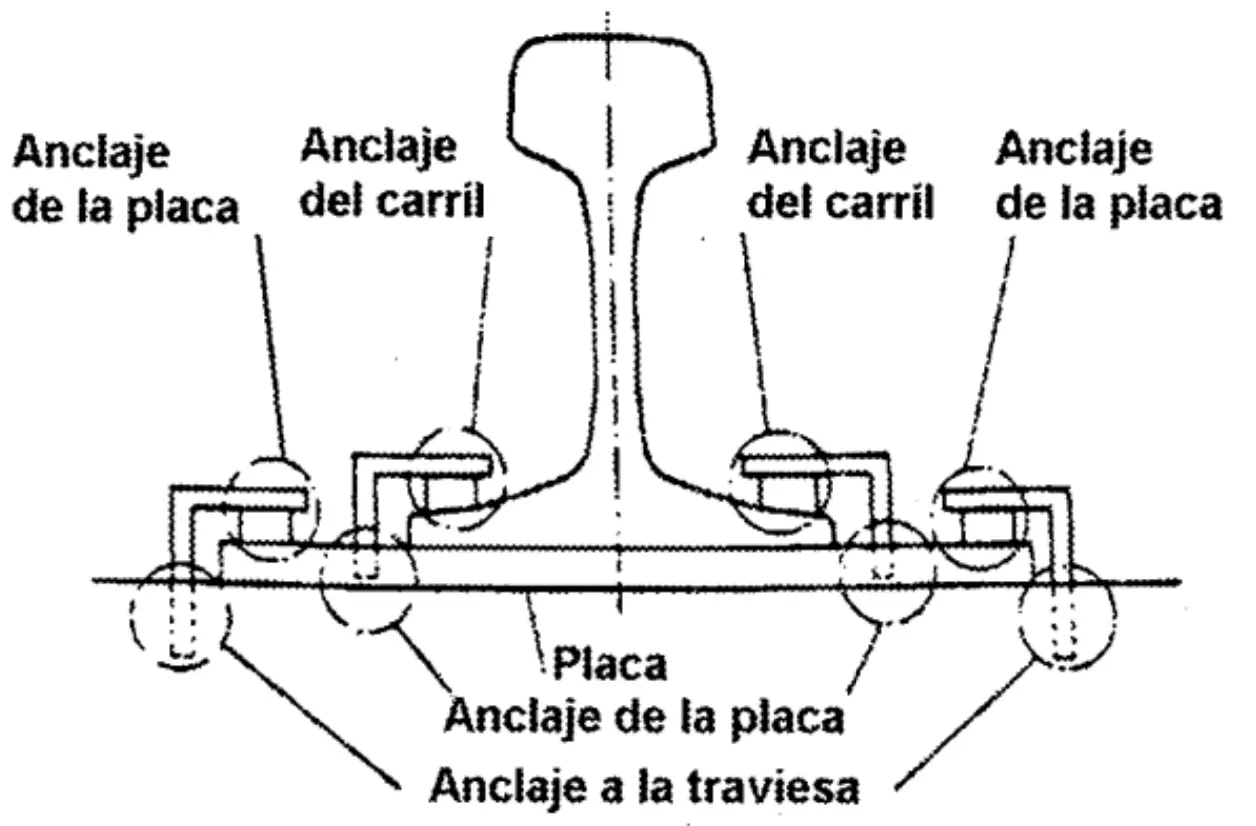
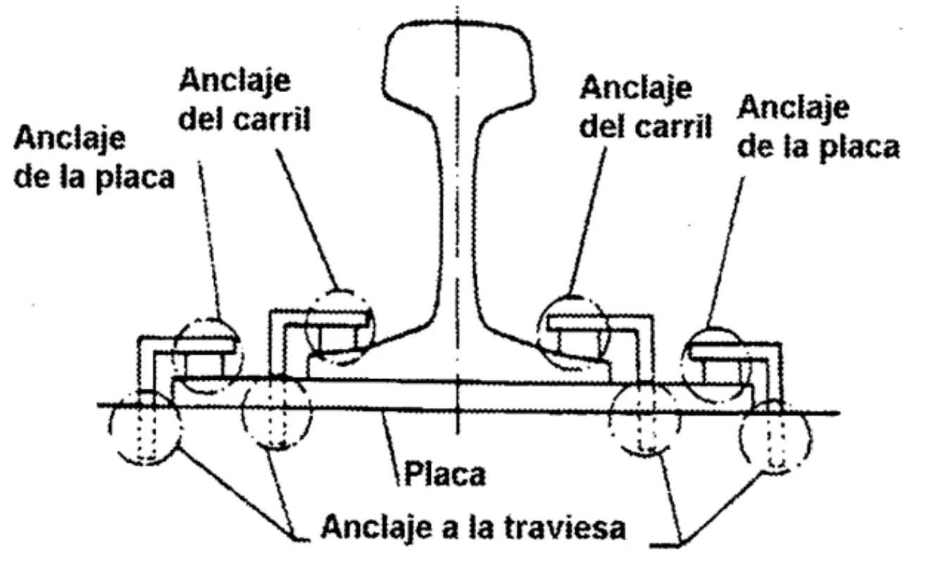
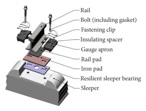
From a constructive perspective, every fastening can be decomposed into a series of specific functional elements. Anchoring elements to the sleeper provide the fundamental mechanical connection with the base structure. The baseplate constitutes the contact interface between rail and sleeper. Plate anchoring elements ensure its position relative to the sleeper. Elastic, insulating, and rail guide elements are responsible for providing system elasticity, insulation, and positional control.
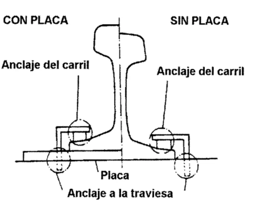
Direct fastening
 Indirect fastening
 Mixed fastening
I.1. Elements: Baseplate
The baseplate constitutes the fundamental transition element that channels loads and movements between the rail foot and the sleeper. Its functions are multiple and interdependent: firstly, it must distribute the load transmitted by the rail evenly onto a larger support surface on the sleeper, reducing pressure concentrations that could be harmful. Additionally, the plate must ensure correct rail positioning, providing adequate inclination and preserving the specified track gauge. Finally, it must prevent longitudinal displacement of the rail under dynamic stresses.
The classification of baseplates is established fundamentally according to the nature of the material used in their manufacture. Metal plates, typically made of steel, have the main function of distributing the load transmitted by the rail through the foot towards the sleeper over a considerably larger contact surface. These elements simply increase the available support surface without experiencing significant deformation under normal load. Conversely, elastic plates, manufactured with rubber, synthetic materials, or wood, provide elasticity to the track system, dampen vibrations transmitted from the rail to the sleeper, and contribute to preventing longitudinal displacement of rails under traction-compression forces.
According to operational and technological criteria, fastenings can be classified into several main types: classic rigid fastenings, elastic spikes, elastic blade or clamp fastenings, elastic clip fastenings, and support fastenings with floating rail, each with particular characteristics and applications.
I.2. Rigid Fastenings on Wooden Sleepers
Spikes (Escarpias)
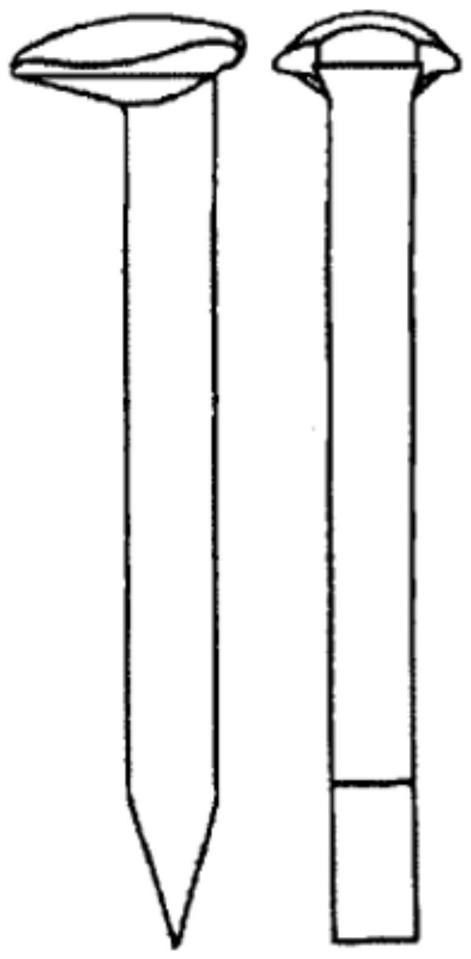
Special nails called spikes represent one of the oldest and traditionally most employed solutions in the railway industry, having been widely used in most railways in the United States and Canada since the origins of the railway system. They are elements of square or octagonal cross-section, with an approximate length of 160 mm, thickness varying between 15 and 18 mm, and weight ranging between 250 and 400 grams. Manufactured in high-quality steel, they are placed by hammering into pre-drilled holes with a diameter equivalent to approximately two-thirds of the spike thickness.
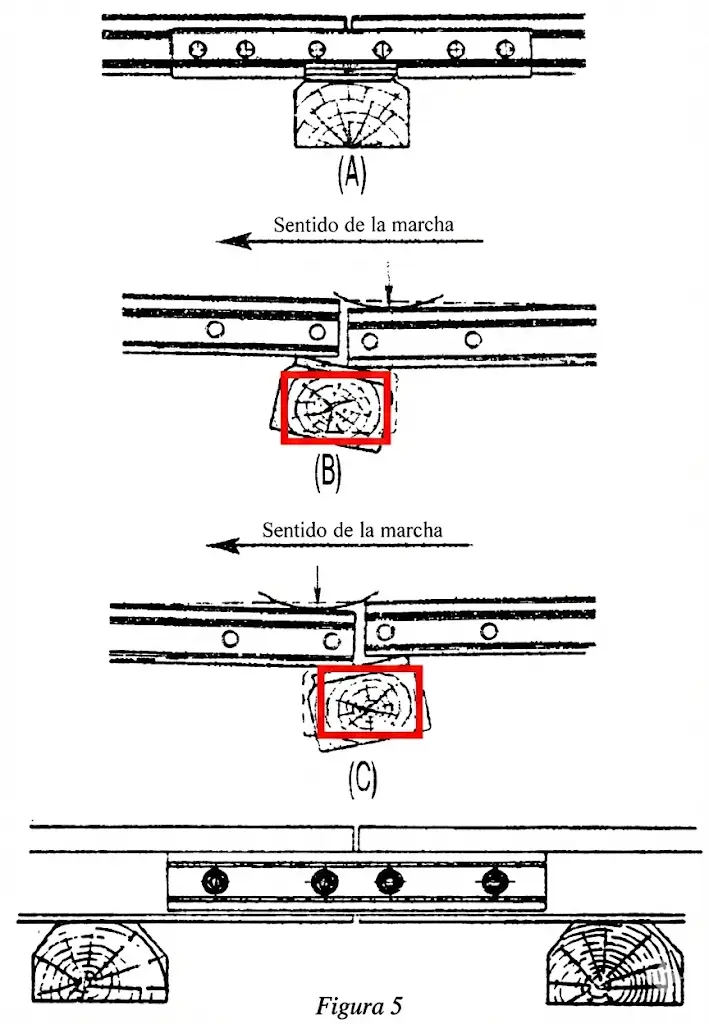
The fastening mechanism of these elements relies fundamentally on the friction generated between the driven part and the sleeper wood. However, over time and under the repeated action of rolling stock loads, the experienced holding force progressively decreases, sometimes even disappearing completely. This loosening phenomenon has multiple causes. One of them is the presence of transverse forces acting on the rail head, which generate overturning tendencies supported by the inner spikes. Additionally, under the concentrated weight of the wheel, the sleeper experiences temporary vertical deformation (effect known as pumping), so that when the load is removed, the rail tends to lift, pulling the sleeper upwards, which causes gradual loosening of the fastening.
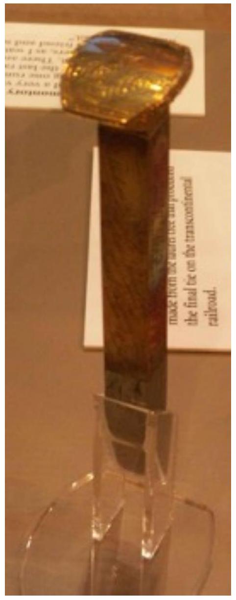
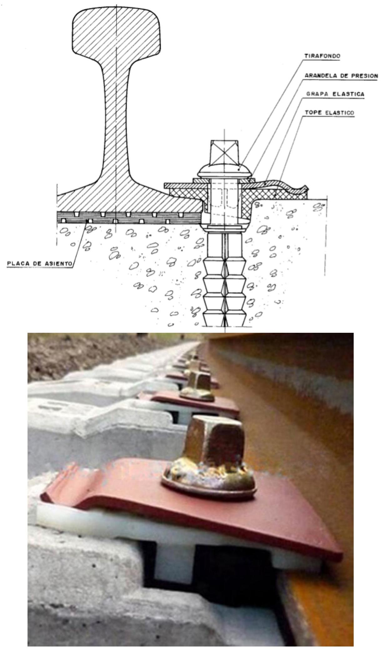
Coach Screw (Tirafondo):
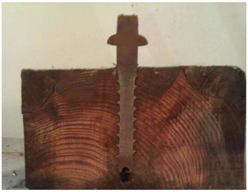
Coach screws are threaded fastening elements, manufactured in galvanized steel, which can present conical or cylindrical geometries. Their most distinctive characteristic is that they possess a considerably widened head compared to the shank, providing a larger contact surface with the rail foot. The head ends in a square or rectangular prism shape that fits into the cavity of the tightening wrench used for its installation in the sleeper.
The screw thread presents a special geometry, typically consisting of a scalene triangle whose upper side is practically perpendicular to the screw axis, a configuration that provides greater resistance to pull-out. The diameter of the hole previously drilled in the sleeper has a decisive influence on the pull-out resistance of the coach screw. This diameter should not considerably exceed the diameter of the screw body, with greater tolerances being admissible in hardwoods than in softwoods; the insertion process is significantly facilitated when the screw has been previously dipped in grease. Once the screw head establishes contact with the rail foot, tightening should not be continued, since a single additional turn can destroy the wood fibers inside, drastically reducing pull-out resistance.
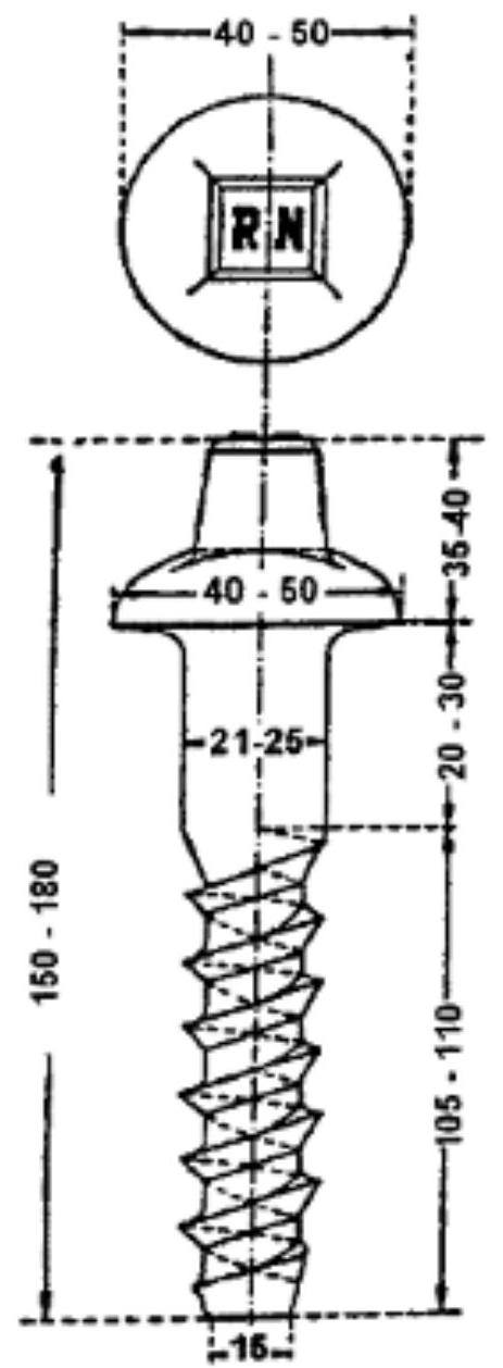
To avoid incorrect installation attempts by percussion, the initials of the railway network or a small pyramid are embossed on the screw head, which would reveal by its deformation any attempt at hammering. Coach screws offer greater resistance than spikes against vertical forces exerted by the foot and are less easily pulled out under forces tending to overturn the rail, this superiority being more pronounced in hardwoods. However, it is estimated that spikes, thanks to their square section, are effective for maintaining track gauge.
The initial pull-out resistance of a new coach screw is high because anchoring is achieved through the screw thread in the helix made in the wood, unlike the spike which is held exclusively by surface friction.
I.3. Rigid Fastenings on Concrete Sleepers
The first attempts to resolve the fixation of rails to reinforced concrete sleepers consisted of adapting the coach screws traditionally used in wooden sleepers, screwing them into wood spikes or blocks embedded in the concrete mass. However, this solution showed significant limitations, as it is not possible to achieve a rigid and durable union between concrete and wood, due to the negative influence of environmental humidity and differences in thermal expansion coefficients of both materials.
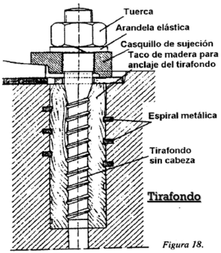
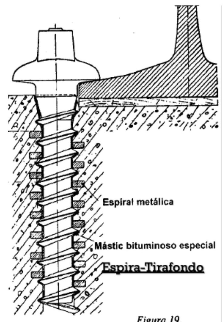
To improve this solution, the use of wooden spikes threaded into a metal spiral housed in the concrete was devised. Subsequent evolution led to the development of the screw-spike, which consists of inserting a metal spiral embedded in the concrete mass, providing a reliable thread for the coach screw. An alternative, although more costly, is to use a cast iron sheath threaded inside, completely embedded in the concrete during its construction, although this solution requires very rigorous manufacturing precision.
I.4. Elastic Fastenings
An elastic fastening is defined as one in which the fixation of the rail to the sleeper is achieved by means of an element that experiences reversible deformation under the action of the stresses transmitted by the rail, being capable of recovering its original shape when said stresses cease. In the track configuration without a rigid baseplate, the elastic element is arranged in such a way that it fixes the rail elastomerically to the sleeper.
Depending on the number of elastic elements working in opposite directions (upward and downward vertical), fastenings are classified as simply elastic or doubly elastic. These fastenings can be grouped into two main categories: elastic blade or clamp fastenings, and elastic clip fastenings, each with specific constructive and functional characteristics.
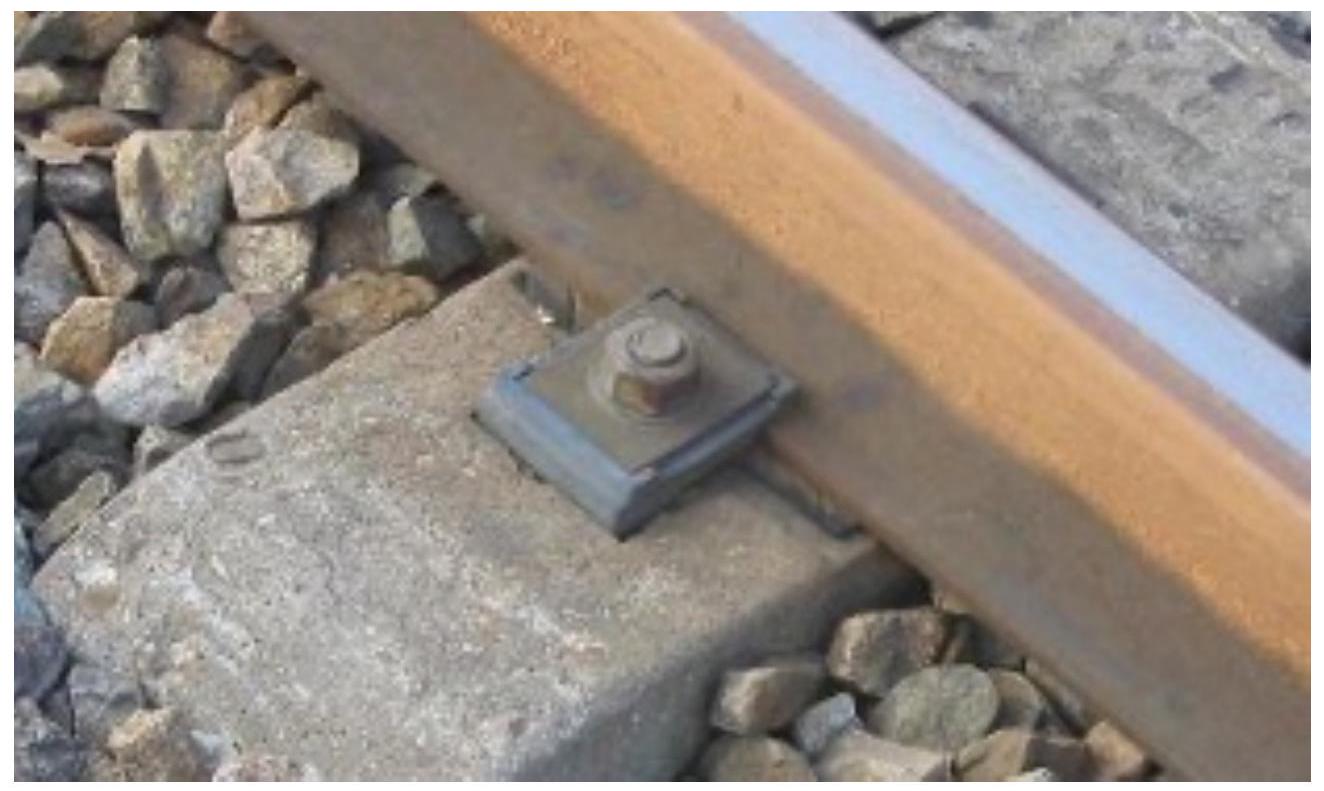
I.4.1. Elastic Clamp Fastenings
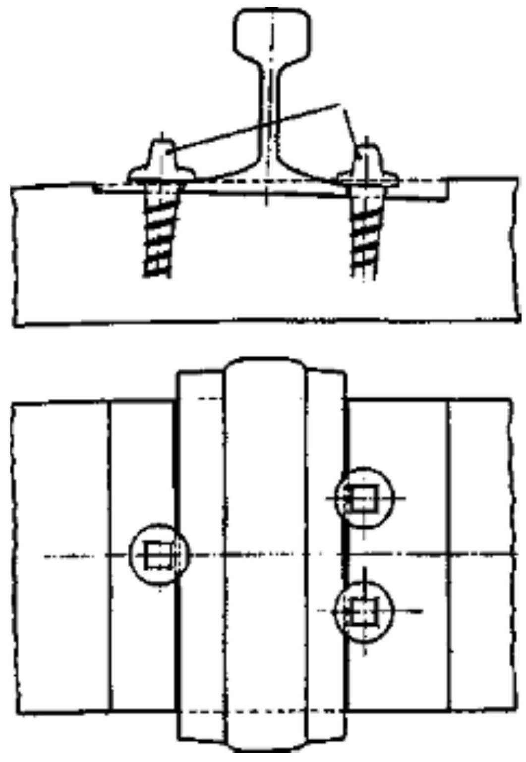
Elastic clamp fastenings provide rail fixation not by means of the head of a traditional coach screw, but by means of a clamp or blade applied over the rail foot, held by a nut threaded onto a bolt that constitutes the extension of the screw-spike shank, lacking the typical widened head. This solution presents the significant advantage of allowing the use of the same sleeper for rails with different foot widths, simply by varying the dimensions of the clamp.
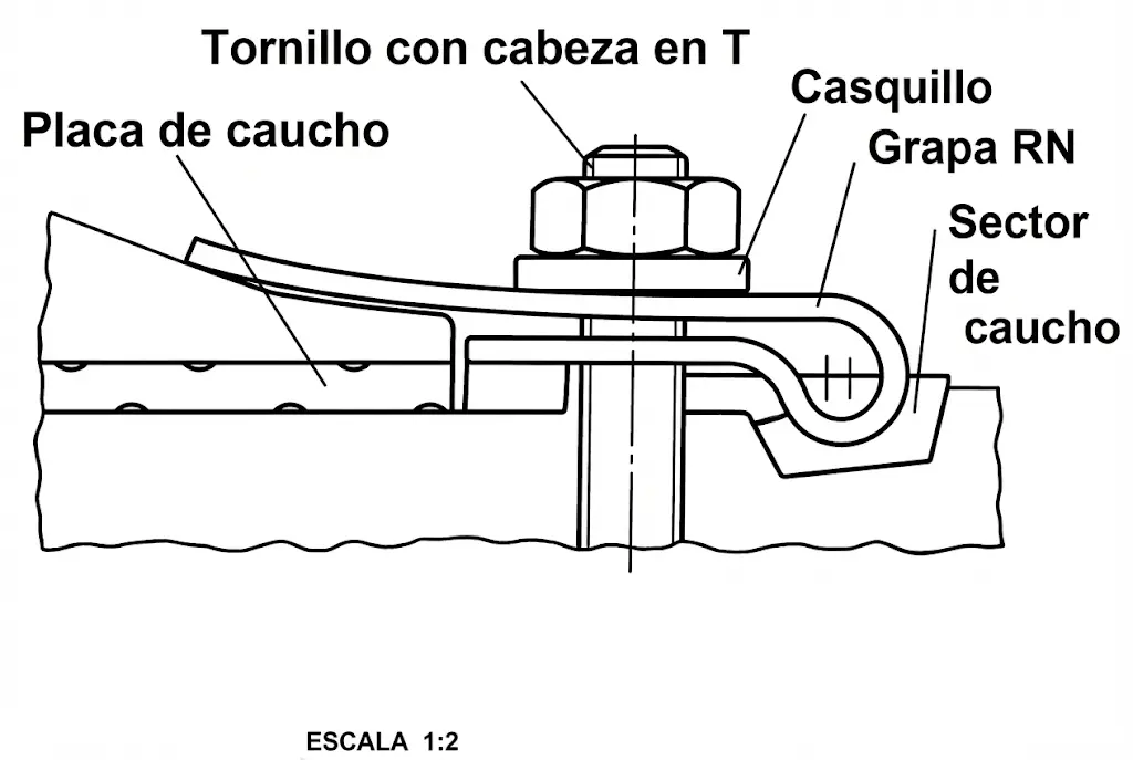
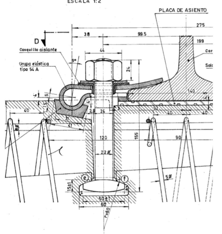
The fundamental structure of these fastenings comprises several components: the clamp or fastening plate, the tightening screw, a rubber sector, and rubber plates that provide the required elasticity. Periodic retightening continues to be necessary, although now it is the nut that experiences displacement. The fact that these periodic retightenings are necessary to compensate for the progressive crushing of the elastic baseplate suggests that it is a solution requiring continuous maintenance.
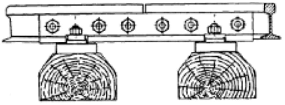
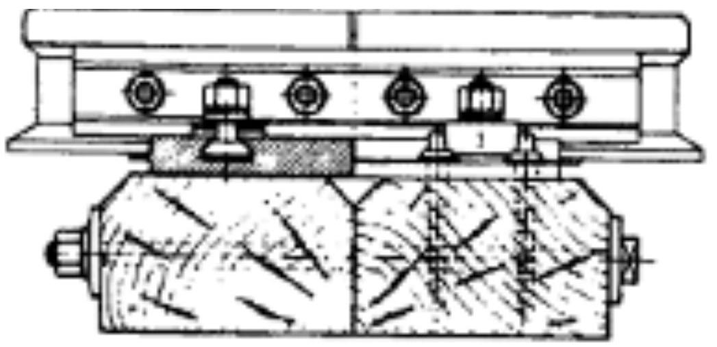
One of the most historically widespread clamp fastenings was the so-called RN, of French origin. This system works effectively on all types of sleepers, although its main application has been on RS sleepers (twin-block or mixed steel and concrete). The elastic components may lose their properties and function inadequately if, due to operational error, they are subjected to excessive tightening of the fixing screws, which generates tensions exceeding the elastic limit of the material, causing permanent plastic deformation. In such a situation, the fastening would behave as a rigid system with all inherent drawbacks.
The RN fastening presents some operational problems: it requires a complex tightening process, has limitations in maintaining track gauge, and provides insufficient electrical insulation. There is also a variant called G-4, designed specifically for wooden sleepers.
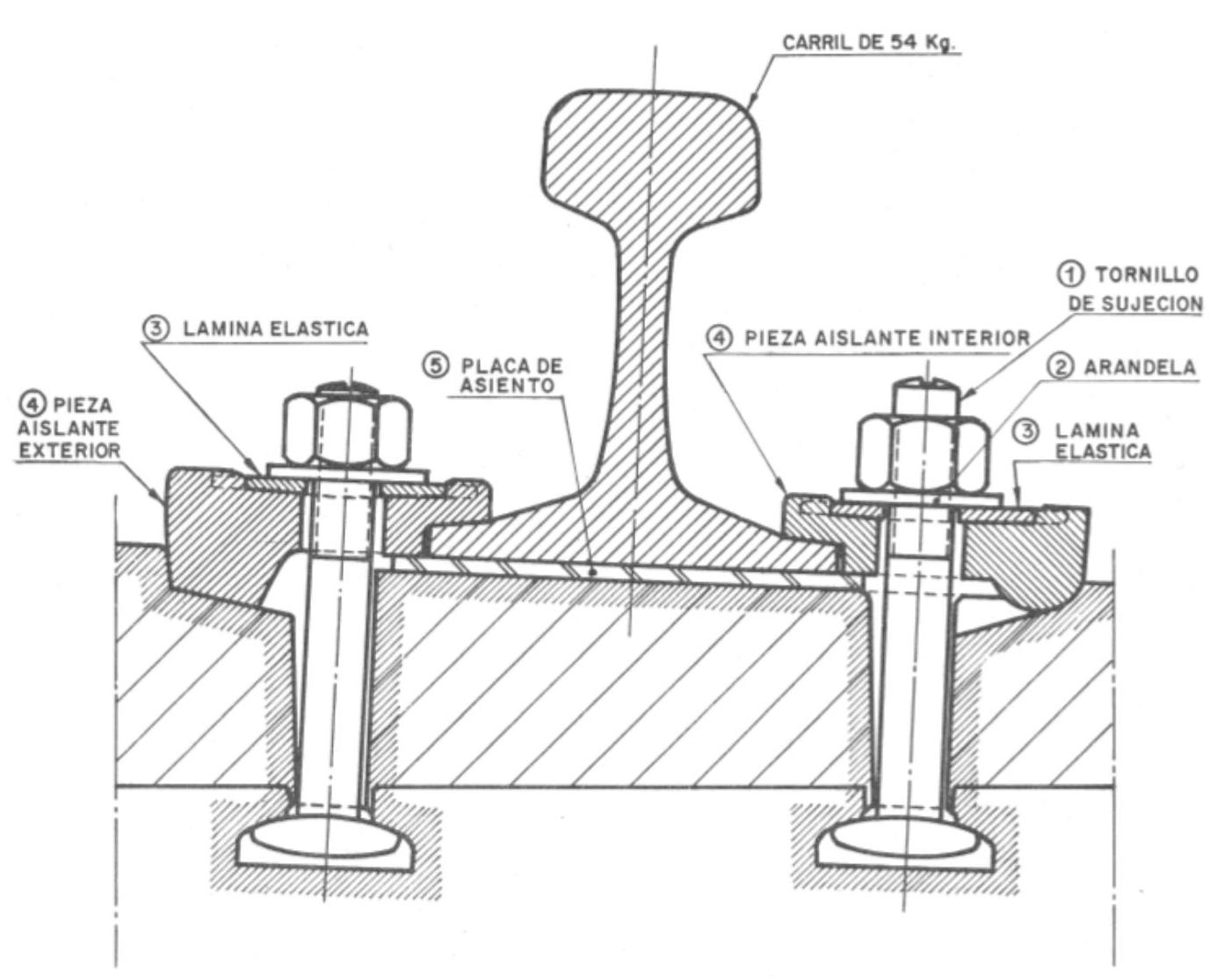
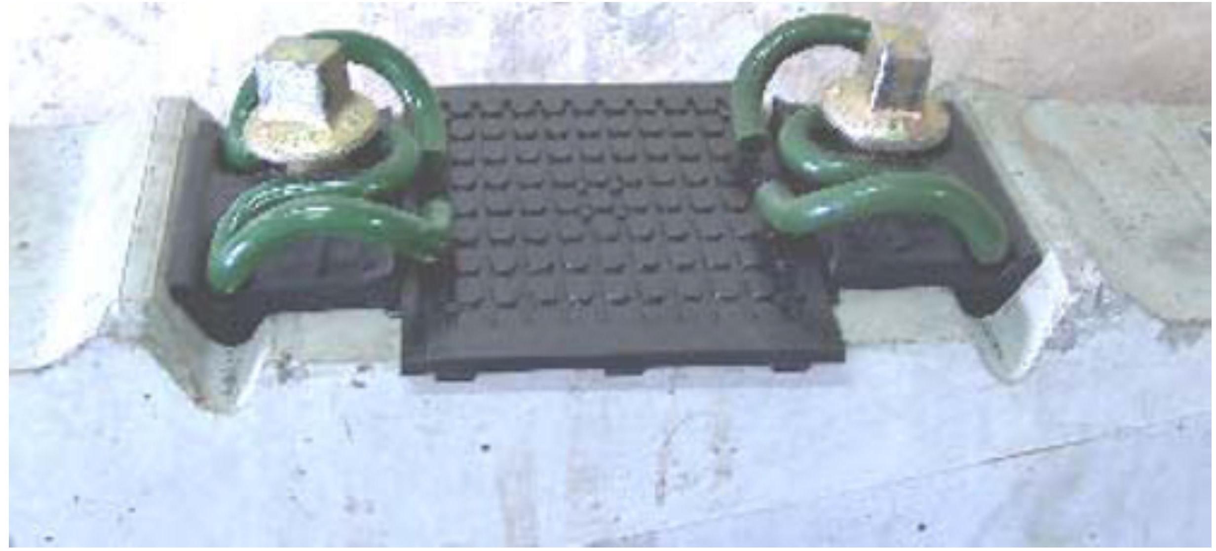
The P-2 fastening was developed in Spain in response to the requirements of high-speed lines, aiming to overcome the limitations presented by the RN fastening. This system effectively resolves the problem of electrical insulation even in unfavorable atmospheric conditions, and practically eliminates the track gauge variations that characterized the previous RN fastening.
The P-2 fastening is composed of two fixing screws to the sleeper that transmit their pressure to the rail foot by means of washers, elastic blades, and insulating pieces arranged internally and externally. Despite its advantages, it presents some significant disadvantages: experiencing loss of elasticity due to repetition of vertical forces which can lead to breakage of insulating clamps, manifesting greater sensitivity to fire action, and having a higher manufacturing price.
The J-2 fastening represents a significant evolution of the P-2 model. Its fundamental differential characteristic lies in preventing eventual contact between the metal plate and the plastic piece by interposing support steps on the upper face of the piece, thus improving durability and long-term behavior.
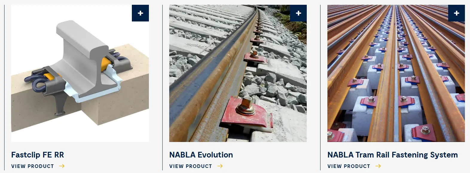
The NABLA fastening was developed in France as an alternative to the RN fastening, being widely used on high-speed train lines. The NABLA fastening design addresses the deficiencies noted in the RN fastening through several mechanisms: it completely ensures the electrical insulation of the track threads, totally eliminates track gauge variations, provides a simpler and more effective elastic union by replacing the clamp with a doubly elastic blade, and considerably simplifies the tightening procedure.
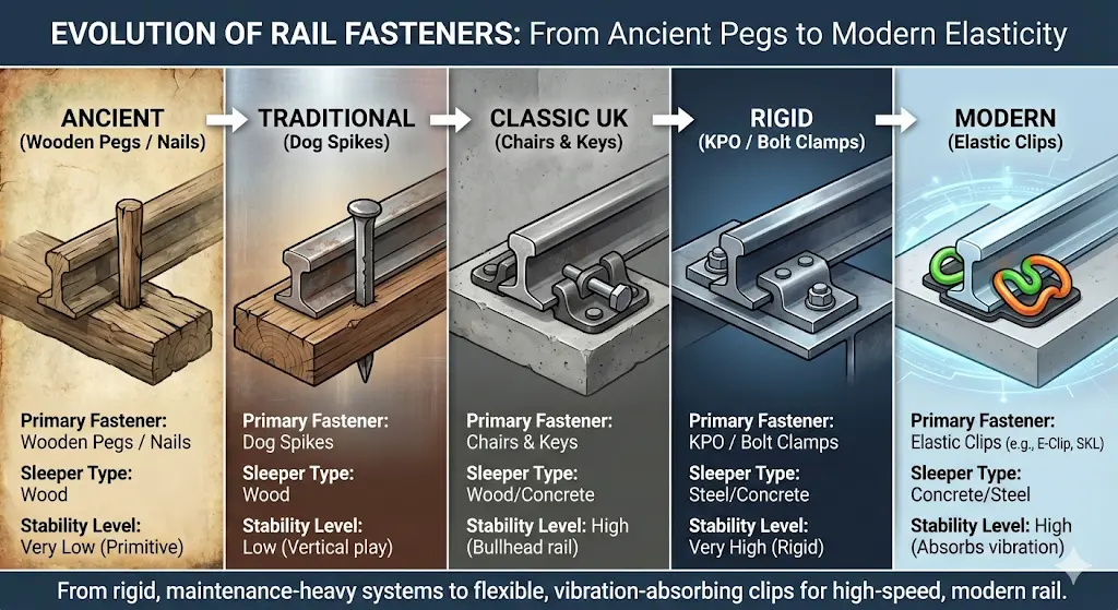
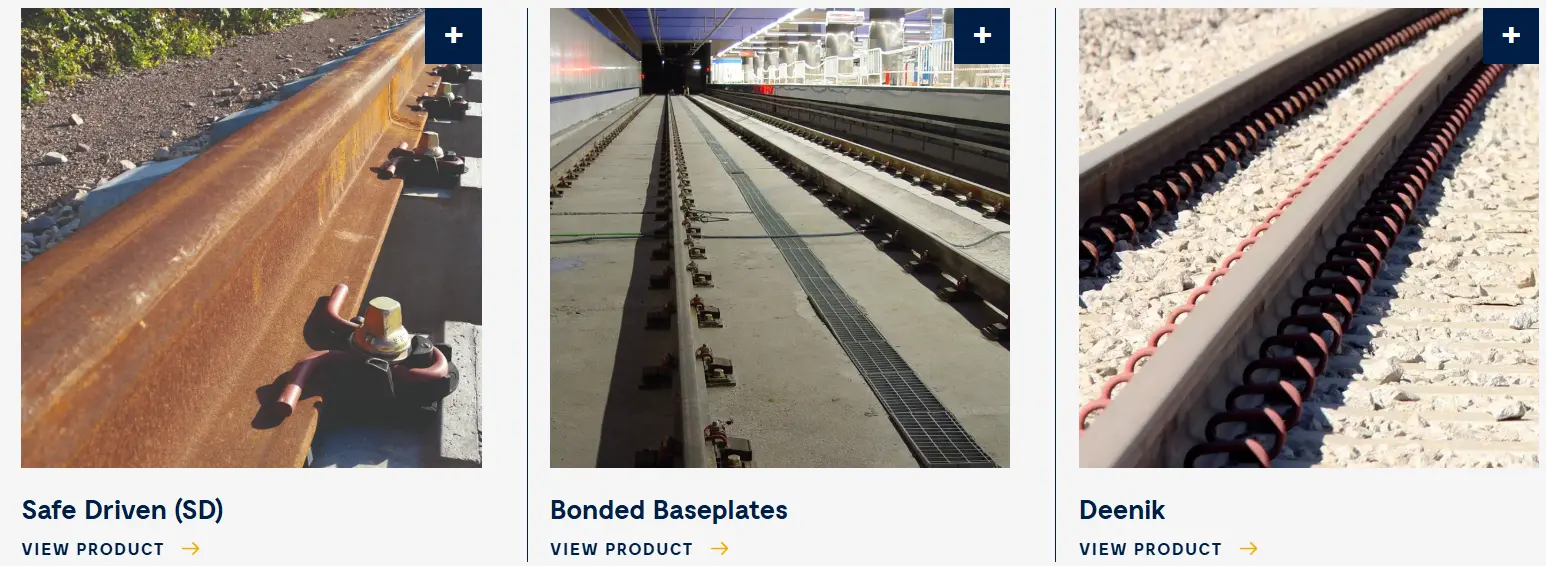
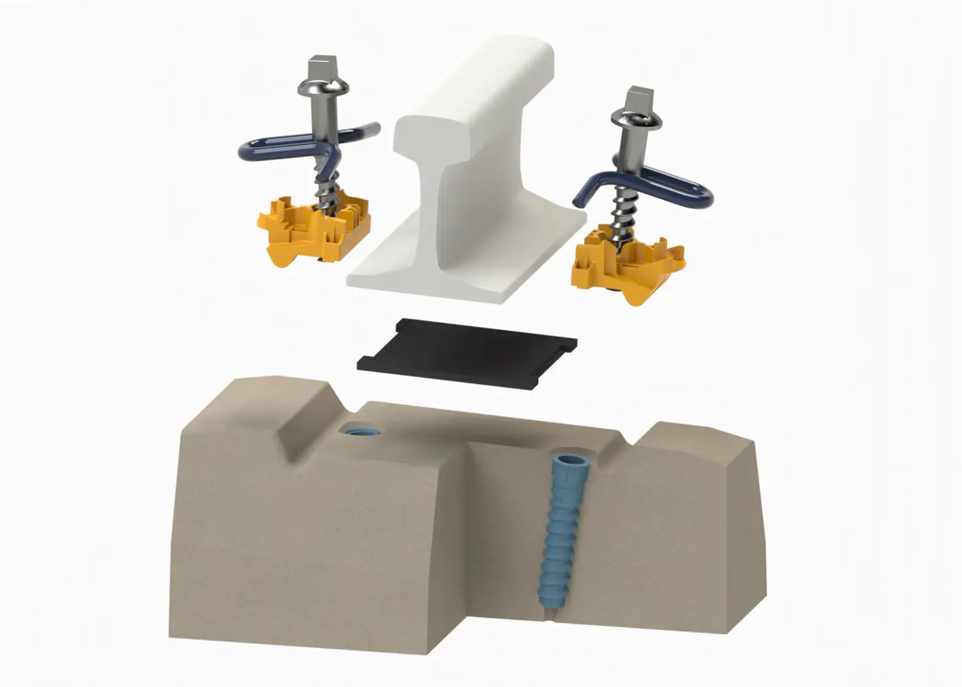
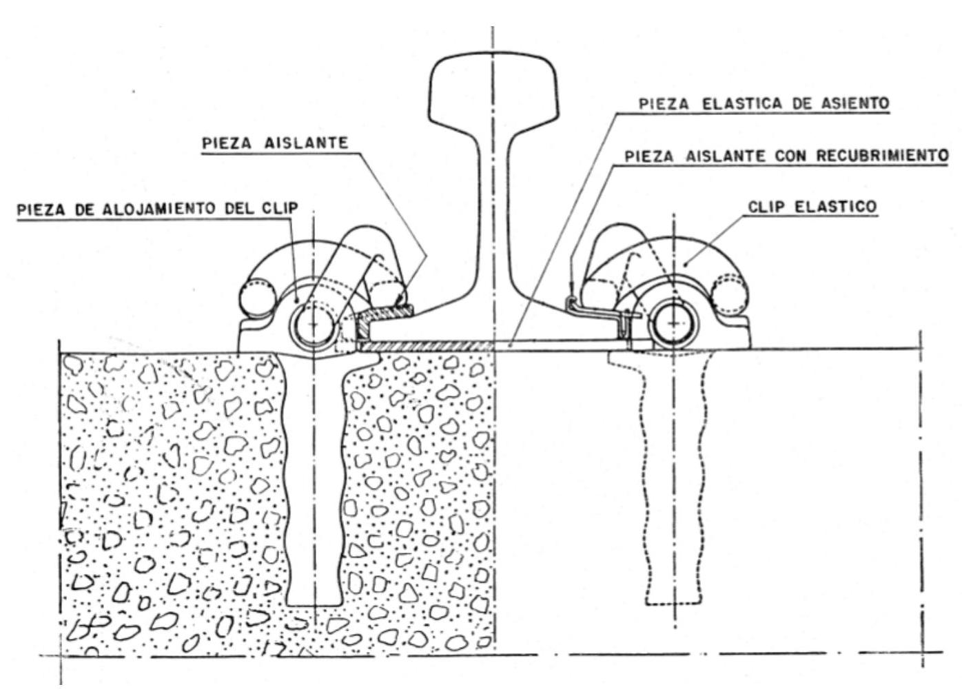
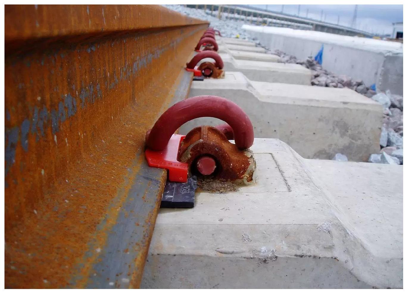
I.4.2. Elastic Clip Fastenings
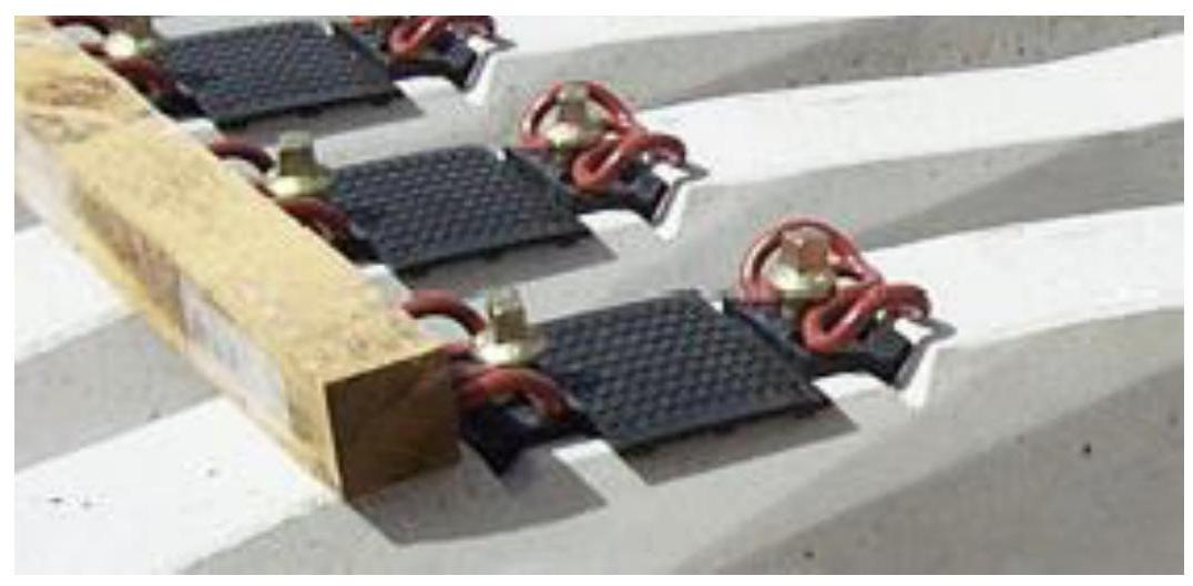
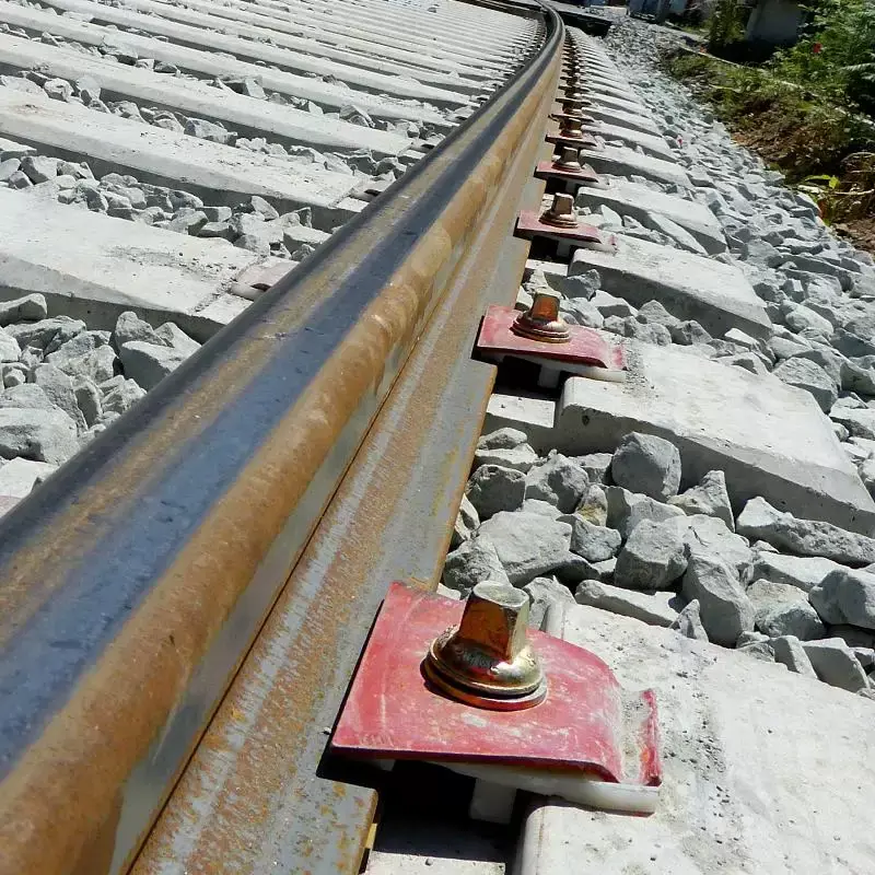
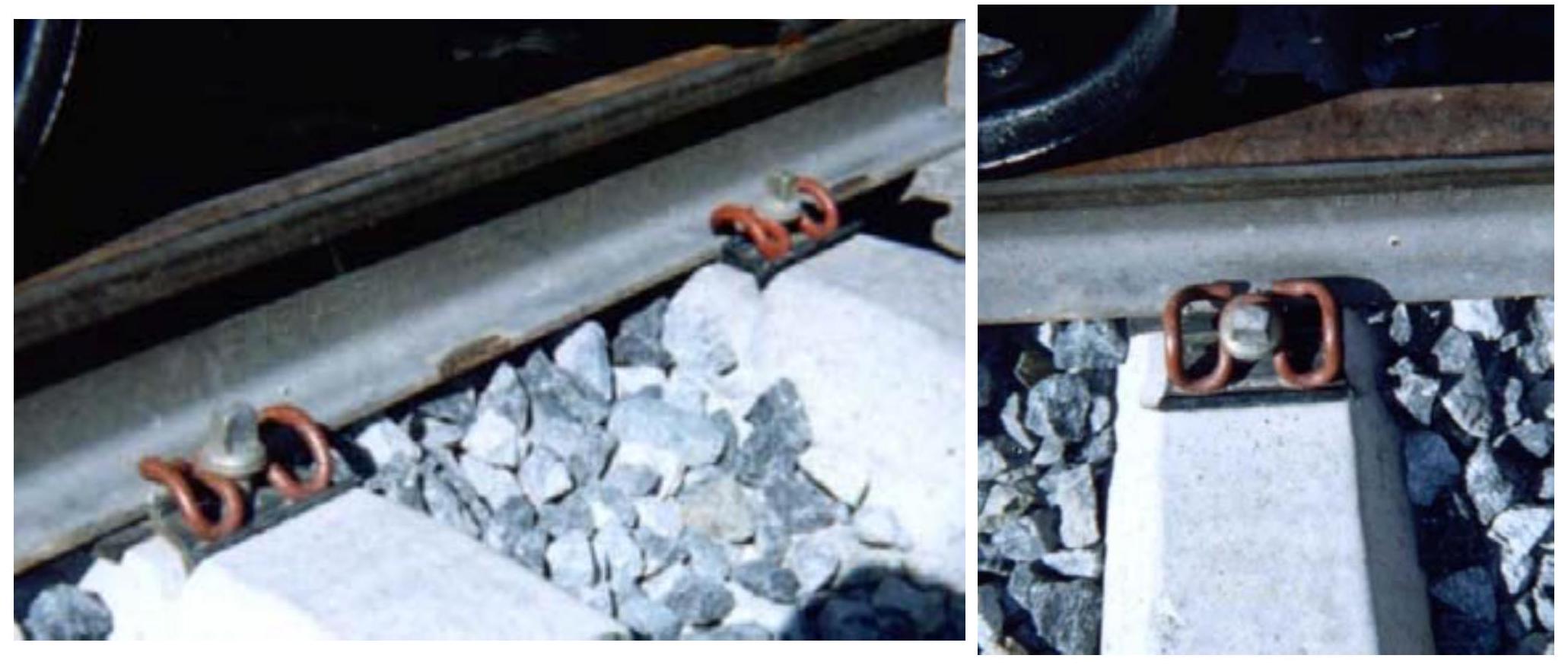
Clip fastenings offer as their main advantage practically maintenance-free operation. However, any deficiency in their construction, excessive material wear, or progressive loss of their elastic characteristics eventually leads to the need for total replacement of the fastening. Among clip systems, the PANDROL fastening has been widely disseminated and used worldwide. Its fundamental constructive characteristic is that it incorporates no threaded element for tightening, which considerably decreases maintenance requirements for the integral track system.
This type of fastening can be mounted on practically any sleeper typology, giving it great versatility. The main operational advantage of the PANDROL fastening consists of the extraordinary simplicity of its assembly and disassembly. As a direct consequence, specialized personnel is not required for these operations, significantly reducing labor cost in installation and maintenance. The robustness of the PANDROL fastening allows its useful life to be practically equivalent to the average life of the rail.
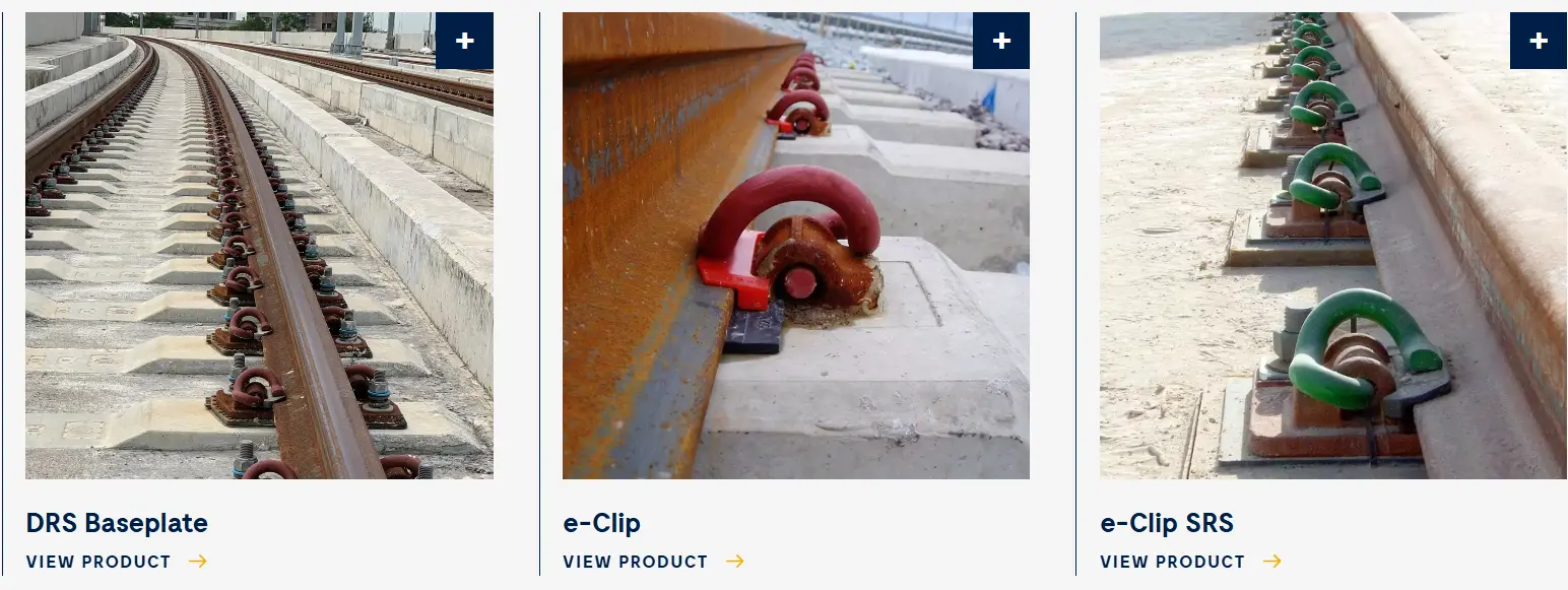
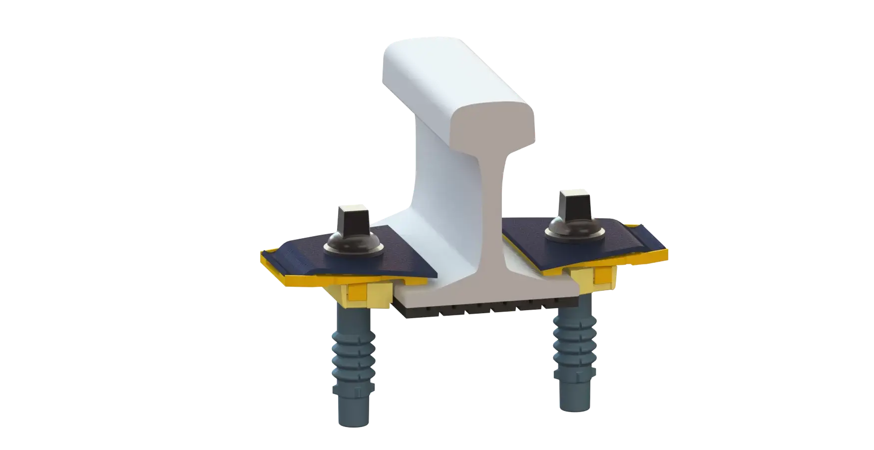
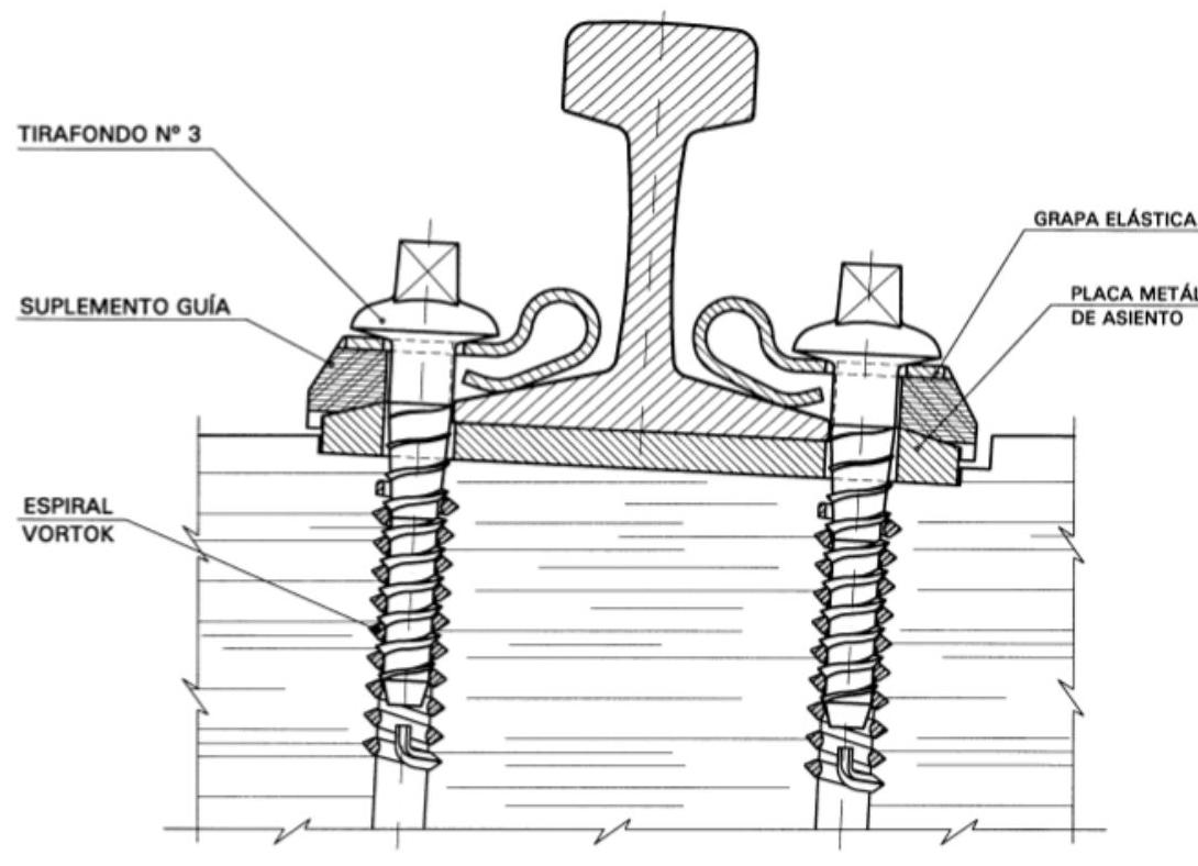
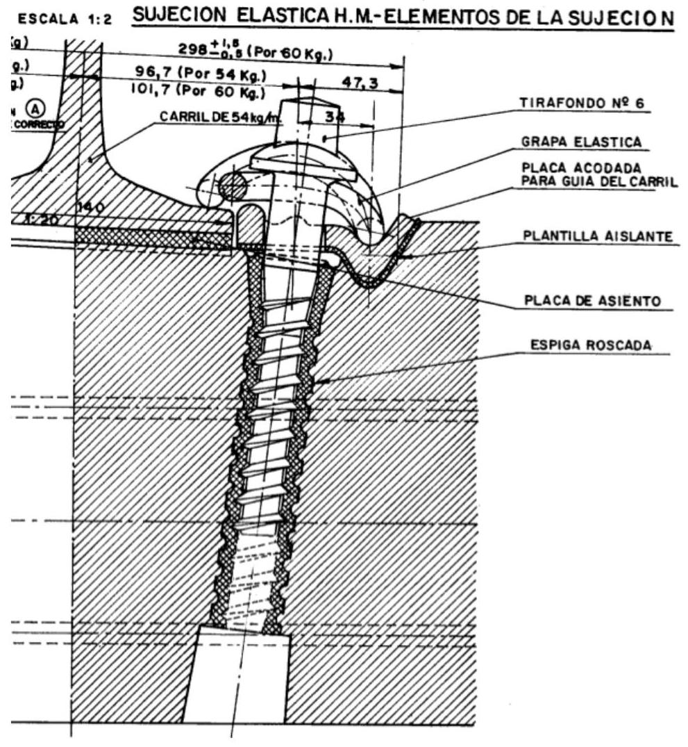
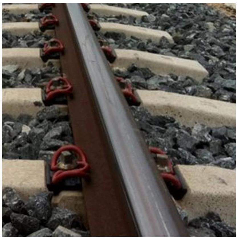
The HM-Vossloh fastening is of German origin and comes in several distinct versions. The SKL-12 variant is traditionally used on wooden sleepers, while in Spain, specifically on high-speed lines, the SKL-1 is used. The Vossloh fastening has achieved wide worldwide diffusion and is easily identified by its characteristic clip shape.
The SKL-1 fastening is designed to be placed on monoblock concrete sleepers, presenting two constructive variants: one for 54-kilo rails and another for 60-kilo rails. The HM clips present a distinctive geometry reminiscent of the Greek letter epsilon. The assembly provides a tightening-deformation curve appropriate for correct fastening operation and good insulation of track threads. Rail tightening results from the bending or torsion work of the clip, this tension being achieved by tightening the coach screw.
I.5. Use of Fastenings in Spain
| VELOCITY | FASTENINGS |
|---|---|
| ≤ 140 km/h | - In C.W.R.: Direct elastic type Vossloh SKL-1 Direct elastic J2. Indirect SKL-12 or G-4. - In jointed track: Direct rigid: coach screws. |
| 160 km/h | Direct elastic type Vossloh SKL-1. Direct elastic J2. Indirect SKL-12 or G-4. |
| 200 km/h | Direct elastic type Vossloh SKL-1. Indirect SKL-12 or G-4. |
| 200-300 km/h | Direct elastic type Vossloh SKL-1. |
| 350 km/h | Direct elastic type Vossloh SKL-1 of high elasticity. |
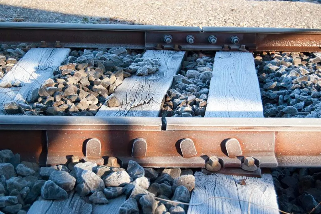
Chapter II Joints
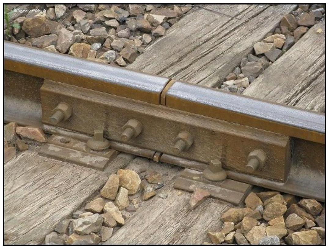
The mechanical connection between two consecutive rails is called a joint. This connection is made by means of specialized metal pieces called fishplates, which establish the longitudinal continuity of the rail. Between the ends of two contiguous rails there is always a small separation called expansion gap, a dimension that is fundamental to allow thermal expansions of the material.
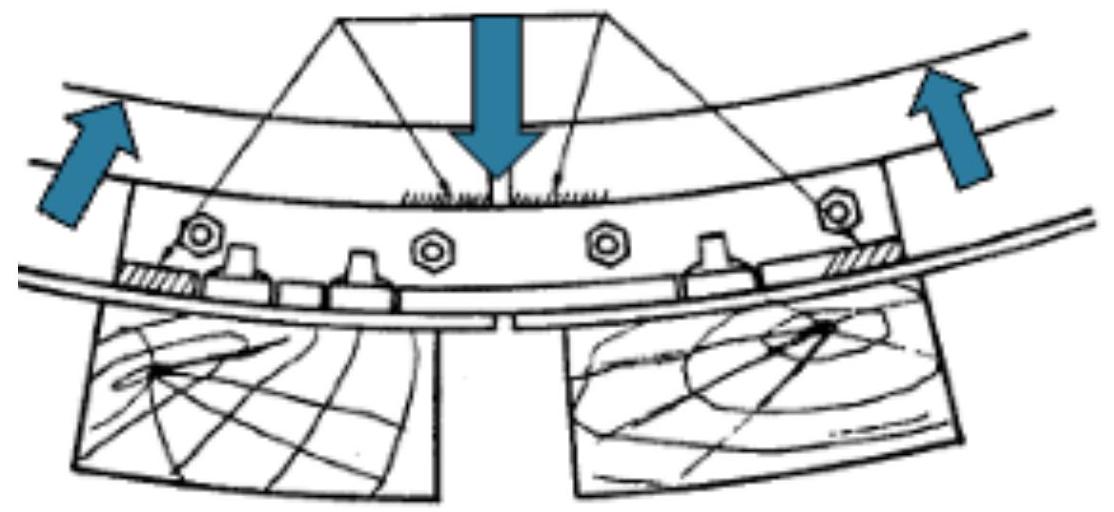
From the point of view of dynamic behavior, joints constitute the weak points of the entire track infrastructure. The fundamental cause of this vulnerability lies in the structural discontinuity they present. In the joint zone, there is a sudden variation in the moment of inertia available to resist bending, which causes abrupt changes in track rigidity, originating impact phenomena upon the passage of rolling stock.
The main function of joints consists of facilitating longitudinal expansion of the rail caused by seasonal variations in ambient temperature. These thermal fluctuations, together with the maximum admissible dimension of the gap, de facto establish the maximum permissible length of the rails. This length limitation is also imposed by industrial rolling technological processes and available transport capacities. Consequently, the presence of joints constitutes an inexorable reality in traditional infrastructure, it being imperative that certain objectives are achieved at these discontinuities. The rails must behave solidly, acting as a continuous beam. The joint must present a resistance to deformation equivalent or very similar to that possessed by the rails themselves. Any vertical or lateral movement of rail ends relative to their counterpart must be prevented, allowing only free longitudinal movement, a consequence of thermal expansion (which is why the diameter of the rail hole must be significantly larger than the diameter of the fishplate connecting bolt).
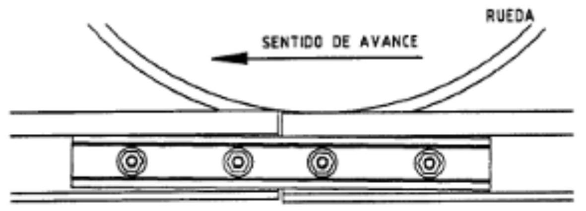
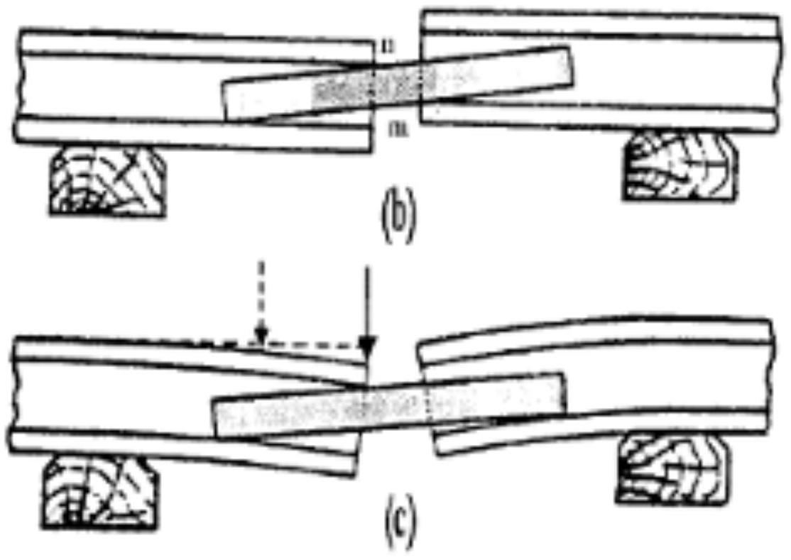
From the perspective of physical behavior, when an axle arrives in the immediate vicinity of the joint, the free end of the rail tends to flex as if it were a cantilever beam, causing a significant impact upon wheel passage. The effects of this phenomenon are multiple and harmful: they increase traction resistance experienced by trains, facilitating longitudinal rail creep, cause accelerated ballast deterioration by hammering, impose bending and deformations on the rail that can become permanent, and generate lack of ride comfort with consequences of fatigue in rolling stock.
Joints
II.1. Position
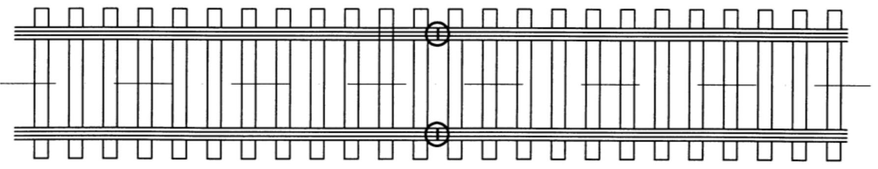
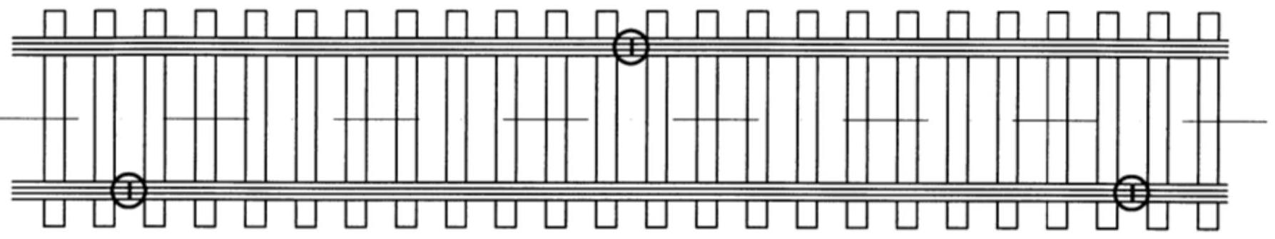
Joints can be classified according to diverse criteria. Regarding the relative position occupied by one rail with respect to the other, they can be square (parallel) or staggered. Square joints are characterized by perfect transverse alignment between both rails, which results in less rolling noise, although they present significant problems in curved sections. Staggered joints, on the contrary, present ends offset laterally, generate more noise, but provide greater geometric stability to the track.
Regarding their relative position with respect to sleepers, joints can be supported, suspended, or semi-suspended. Supported joints, also called joints on sleeper, rest directly on a sleeper. Impacts received by bending of the rail end cause tilting of the sleeper on its support seat, ballast becomes rarefied and displaced under it, resulting in a false support that makes the joint potentially dangerous.
Suspended joints, also known as air joints, are located between two contiguous sleepers. The sleepers on which the ends of the fishplates rest are called joint sleepers, and are typically placed closer together than conventional intermediate sleepers. This type of joint is preferred by most railway administrations, including Adif. It results more elastic than the supported version and avoids the harmful anvil effect that characterizes the previous configuration.
Semi-suspended joints constitute an intermediate configuration where fishplate length is such that it reaches the joint sleepers. This arrangement was conceived in an effort to increase the resistance of purely suspended joints. Certain specific types of fishplates can also be used to prevent longitudinal rail creep. It is fundamental to maintain appropriate separation between joint sleepers to allow track tamping movements.
A specialized variant is the semi-supported joint on juxtaposed sleepers, where the joint rests simultaneously on two sleepers instead of only one. These two sleepers are joined by pins, effectively forming a wider sleeper. This configuration partially mitigates the harmful effect described in simple supported joints, simultaneously facilitating tamping.
II.2. Parts
Structurally, every joint is composed of several functional elements. Metal fishplates constitute the fundamental component providing mechanical union between the ends of two rails. Specialized bolts ensure firm connection of fishplates to rails. Joint connections, when required, establish electrical continuity between the two joined rails, a critical aspect for traction and signaling systems.
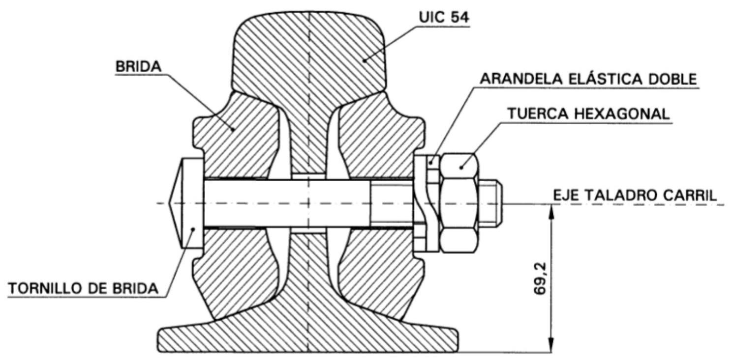
II.3. CROSS SECTION
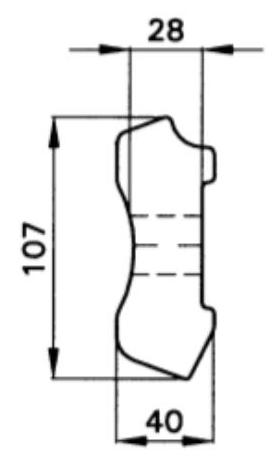
FISHPLATE
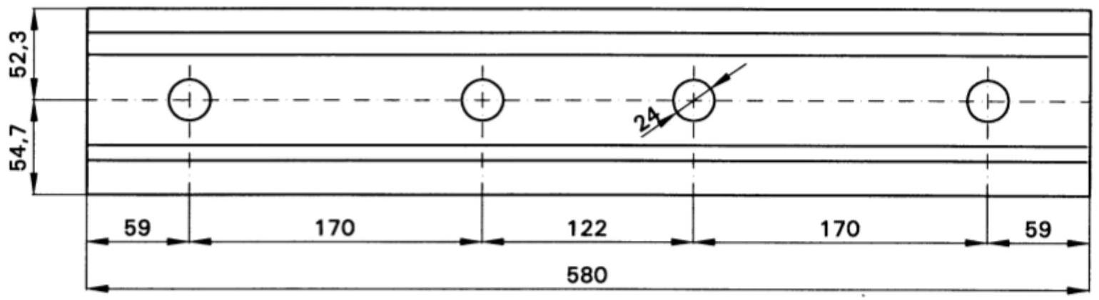
II.4. Fishplates
The metal fishplates fulfill the fundamental function of joining the ends of two consecutive rails so that their longitudinal axes remain coincident and the position of both is completely immobilized in both the horizontal and vertical planes. These elements withstand very significant stresses during operation. When an axle approaches the joint, the rail end tends to flex like a cantilever beam, but this flexion is prevented by the presence of the fishplate. The fishplate receives a considerable load applied approximately at half its length and transmits it to the feet of both rails through contact points at the fishplate ends.
To function correctly, the fishplate must be perfectly fitted between the rail head and foot. Considering that the force to be transmitted acts in a direction parallel to the vertical axis of the rail, it is evident that the rail head must present on the inclined planes located at the bottom the least possible inclination with respect to the horizontal, at least from this specific point of view. However, there is a counteracting effect: the progressive wear that occurs at joints.
Under the continuous action of bending and shocks characterizing joint behavior, relative movements are generated between rail and fishplate, causing wear affecting mainly the transmission zones of main forces.
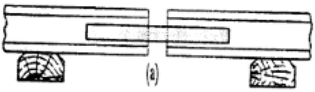
 In general terms, the union of components is secured by bolts passing through the rail and both fishplates solidly. In circumstances where it is not convenient to drill the rail (provisional jointing of very short duration) or sufficient time does not exist (emergency jointing), securing is performed by special “C” shaped pieces with a central tightening screw which, passing under the rail, embrace the pair of fishplates from the lower side.
Aspects constituting characteristic weaknesses in these elements can be synthesized in the following critical points: appearance of cracks in the fishplate, frequently initiated from the drilled holes; loosening of bolts or their deformation under load, reaching in extreme cases complete breakage; loss of electrical insulation in those fishplates that must fulfill this special function in track circuits.
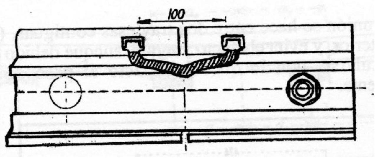
II.5. Electrical Circuit Continuity
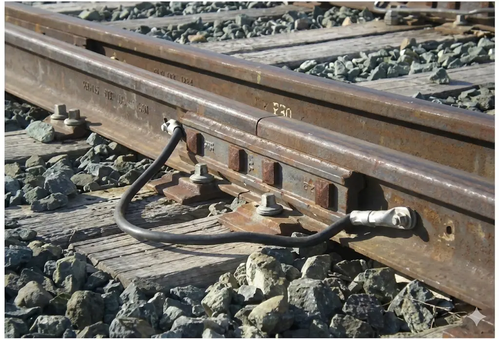
In electric traction systems, return current circuit continuity is generally not guaranteed in joint zones, or connection quality is insufficient. To ensure adequate conductivity, an electrical connection is made between two consecutive rails made by a copper cable of appropriate section whose terminals are introduced into steel sleeves. These sleeves are welded to the rail on its outer part on both sides of the joint. When conductivity is necessary only for signaling circuit requirements, the connection is simplified using welded wires of smaller section.
When it is necessary to achieve electrical insulation in a rail cross-section to allow track circuits used in signaling to operate correctly, specialized design insulated joints are used. These elements incorporate multiple insulation features: insulating linings arranged between fishplates and rail at the fishplate-rail interface; a rail cross-section composed of insulating material placed between the two consecutive rails to break rail-rail continuity; and insulating cylinders placed around bolts to prevent any electrical contact through holes drilled in the rail web.
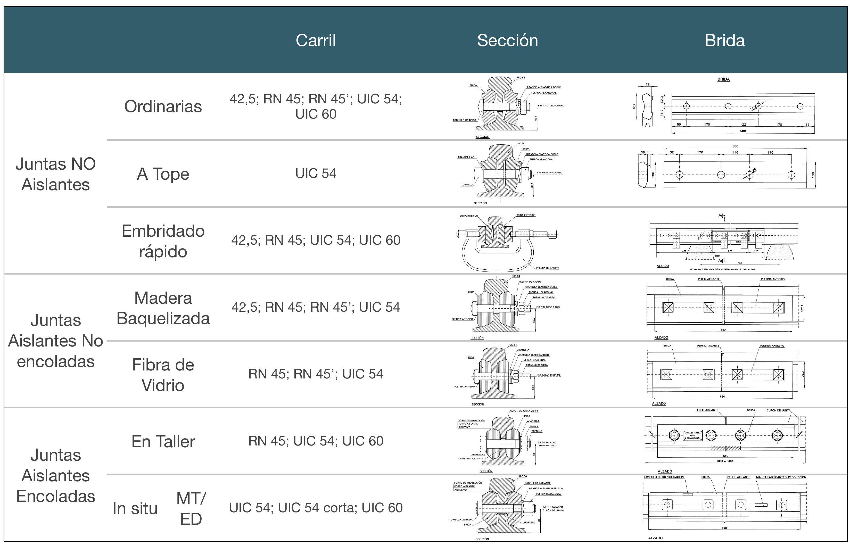
II.6. Classification
Bolted rail joints can be classified according to multiple criteria, considering both their field of application and distinct materials employed in the manufacture of their fishplates and components. This classification is essential to select the most appropriate joint type for each specific operational context.
Firstly, there are non-insulating joints, used to provide continuity to the track without electrical conditioning. Within this category are ordinary joints, which are elements designed to join two rails that do not require electrical insulation of any type. These joints consist of high-strength steel metal fishplates, standard fishplate bolts, and complementary fixing elements. Their applications include traditional jointed track and provisional jointing during transitory phases of continuous welded rail creation.
Butt joints aim to eliminate the gap that naturally arises in an ordinary joint. To achieve this, they incorporate considerably more robust fishplates in which the distance of holes from the central fishplate axis has been significantly reduced, as well as bolts of larger diameter and mechanical strength. They are manufactured specifically for UIC 54 rail and are traditionally applied in joining rails connecting to the crossing nose in type B3 turnouts and type B crossings incorporated into continuous welded rail tracks.
“CE” rapid jointing joints are temporary solutions where steel fishplates are held by a clamp called a tightening press, dispensing with bolts used in ordinary joints. They are used when it is not convenient to drill the rail (provisional jointing) or when there is no temporal availability (emergency jointing).
On the other hand, there are insulated joints, used specifically to achieve longitudinal electrical insulation of rail threads in track circuits. An important distinction is made between those carrying a union glue and those lacking it. Non-glued insulated joints are those employed in traditional jointed track and type A turnouts. In the Spanish network, depending on the material their fishplates are manufactured from, bakelized wood joints and fiberglass joints are distinguished.
Glued insulated joints are used in tracks with continuous welded rail. Depending on their manufacture, two variants are considered: Workshop Glued Insulated Joint (JAE), manufactured in specialized workshop facilities, incorporating steel metal fishplates, fishplate bolts, complementary fixing elements, insulation and gluing elements, and two rail coupons. It is applied in type B, C, V and P turnouts and in general track with continuous welded rail. The second variant is the In-situ Glued Insulated Joint (JAE), which unlike the previous one, is mounted on the track itself during its construction, using existing rail.
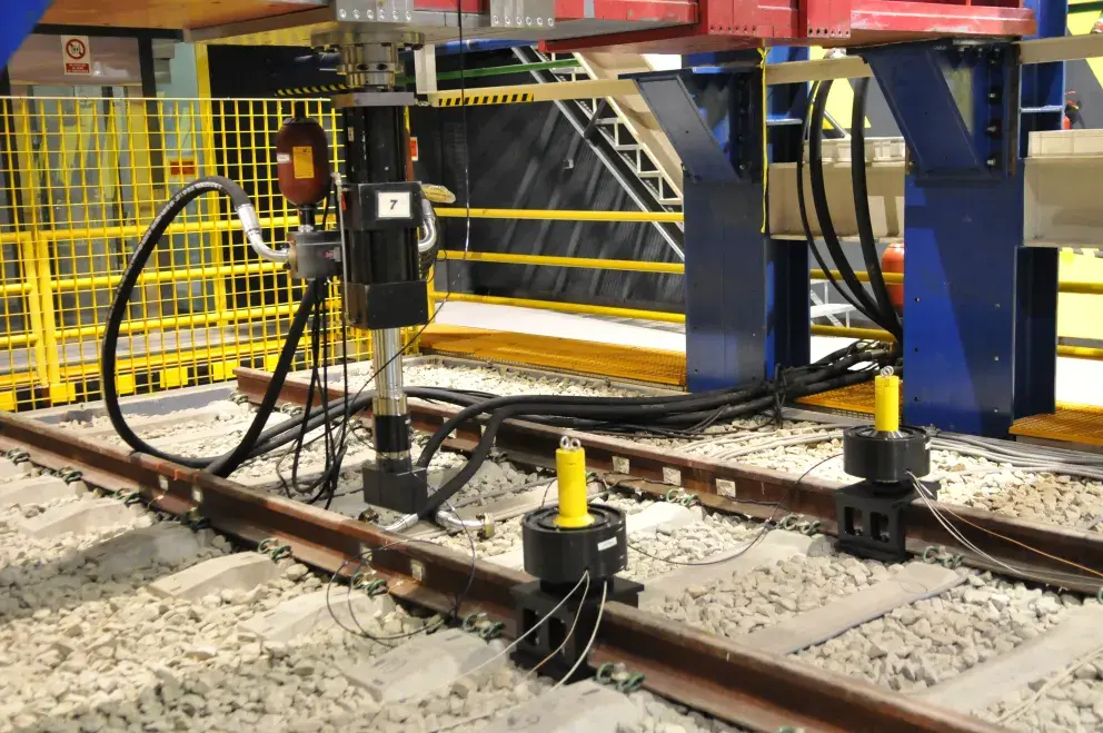
II.7. Caminsan Test
Glued insulated joints (JAE) experience progressive deterioration during passage of trains, eventually losing their fundamental function of achieving electrical insulation in the cross-section. To evaluate and certify the behavior of these elements under real service stresses, a standardized test procedure has been established.
CAMINSAN defines technical conditions for a laboratory test with loads of magnitude and point of application such that they generate deflections (vertical deformations) and bending moments of the same order of magnitude as those experienced by the JAE during its operating life in service. A test device was designed according to normative specifications. Vertical load is 17.64 tons (corresponding to UIC-60 rail); span between supports is 64 centimeters; applied longitudinal load is ±45 tons; number of vertical load cycles is 3,000,000 (representing the number of axles circulating over a JAE during a five-year service period on a first category line of the Adif Basic Network); number of longitudinal load cycles is 1,826.
This rigorous test was adopted as OFFICIAL HOMOLOGATION TEST FOR GLUED INSULATED JOINTS by RENFE (now Adif), constituting a mandatory requirement for any JAE to be installed in the Spanish network.
Chapter III Jointless Track: Continuous Welded Rail (CWR)
Throughout the previous analysis, the multiple inconveniences associated with the existence of joints in track infrastructure have been identified and documented, as well as the limited results that can be achieved in their mitigation through progressive improvements in fishplate design. The radical solution to the problem consists in their complete elimination through the welded union of individual rails. By welding together rolled rails, whose length is limited by industrial rolling processes and transport restrictions, a continuous jointless track is obtained, called track with Continuous Welded Rail (CWR), presenting significantly superior operational and comfort advantages.
For a jointless track to operate satisfactorily and fulfill its functions safely and durably, several fundamental requirements must be met: The length of the welded section must be as great as possible, minimizing the quantity of residual joints. The track must be as heavy as possible, using heavy rails and concrete sleepers providing significant mass. The track must be very well leveled and aligned in all directions. Curves of radius less than 450 meters should not exist, with the recommended minimum being 800 meters. The ballast profile is critical: it must be angular and of good particle size quality. Fastenings must always maintain positive pressure on the rail, high torsional resistance being necessary, which implies the use of advanced design elastic fastenings.
III.1. CWR: Previous Concepts
Historically, it was assumed that the presence of an expansion gap was an unavoidable necessity in joint design. This separation should be a function of the extreme temperatures the rail would experience during its operating life. A maximum admissible gap of 20 millimeters was established to avoid the magnitude of hammering upon passage of traffic in winter conditions. Simultaneously, the gap should not be excessively small, to prevent it from closing completely in hot time periods, which would produce harmful longitudinal forces capable of deforming the track.
Under the theoretical hypothesis of free expansion without restrictions, the length variation experienced by a rail of initial length \(L_{0}\) is given by:
\[\Delta L=L_{0} \cdot \alpha \cdot \Delta T\]where \(\alpha=10.96 \cdot 10^{-6}\) is the linear thermal expansion coefficient of rail steel.
Under this consideration of completely free expansion, the maximum rail length would experience in hot weather (temperature increase \(\Delta T=100^{\circ} \mathrm{C}\)) the following variation:
\[L-L_{0}=L_{0} \cdot(1+\alpha \cdot \Delta T) \rightarrow\left(L-L_{0}\right)=0.02 m \rightarrow L_{0} \cong 18 m\]This consideration suggests that rails of approximately 18 meters in length would be the reasonable maximum under free expansion.
III.2. CWR: Restricted Expansion
If the concept of free expansion were applied to a continuous welded rail of, for example, 300 meters in length, expected theoretical expansions should be in the order of 34 centimeters under a temperature increase of 100 degrees Celsius. However, experimental evidence demonstrates a behavior radically different from that predicted by free expansion theory.
When a continuous rail with free ends A and B is observed experimentally, marking reference points C, D, etc., on its surface and referring them to fixed external pickets, a notable phenomenon is observed: points situated in a certain central zone, between C and D, practically experience no movement. Conversely, ends A and B, as well as points P near the rail ends, occupy positions further away than in their primitive situation. If x denotes the distance DP in initial conditions, subsequently with temperature increase it will be \(x+\Delta x\), resulting in real expansions much smaller than theoretical predictions.
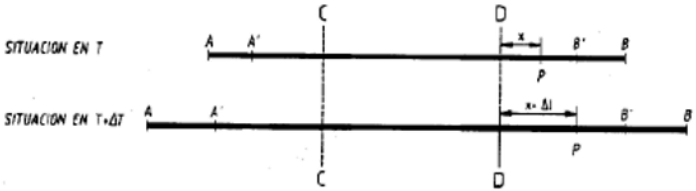
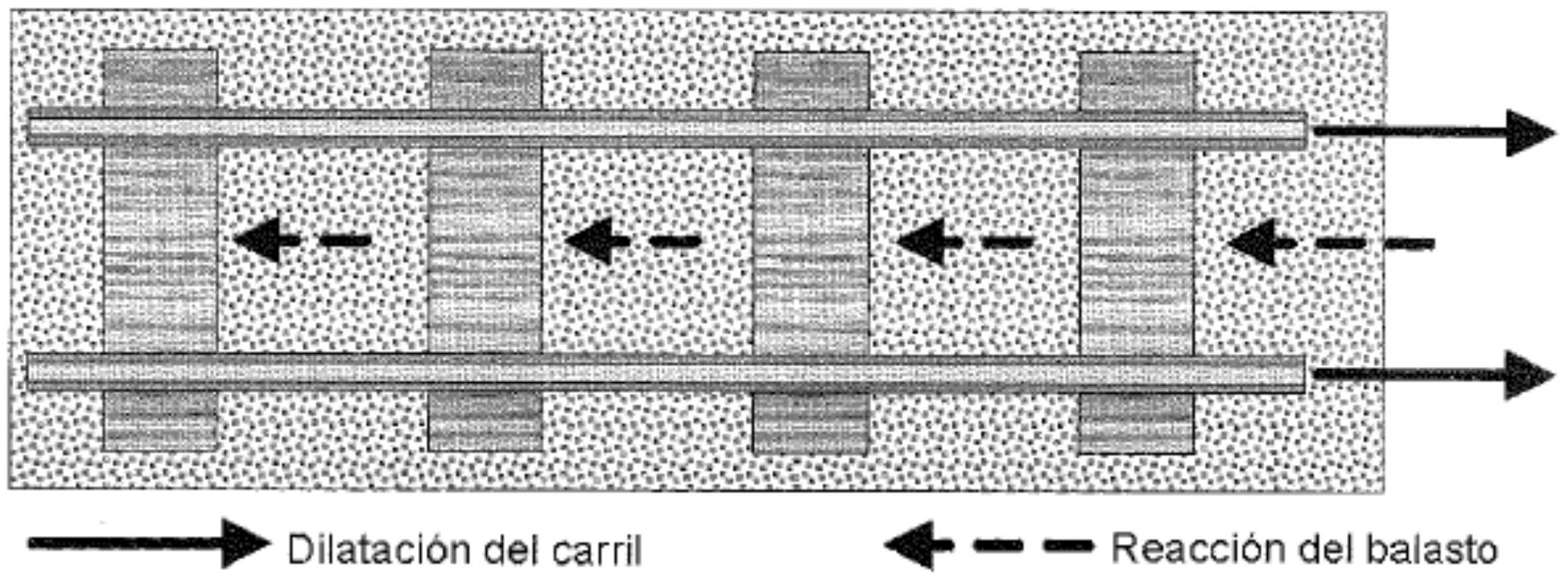
The physical explanation of this phenomenon resides in that, in fact, there is no free expansion but a restricted or confined expansion. The thermal expansion of the rail is constrained by the friction generated between ballast and sleepers during displacement of the latter, a phenomenon resulting from the fact that both are solidly united to the rail by fastenings.
The value of this resisting friction force (r) varies significantly depending on the type of sleeper used:
- For wooden sleepers: r = 500 kg/m
- For twin-block concrete sleepers: r = 750 kg/m
- For monoblock concrete sleepers with heavy rail: r = 1,000 kg/m
These friction forces constitute the fundamental mechanical restriction limiting rail expansion in the extreme zones of the continuous welded rail.
- In jointless track, rails are welded and variations in their length are totally blocked, except for sections where expansion devices have been installed. Inside, longitudinal forces are generated which must be withstood by track infrastructure through the fastening of rail to sleepers and, by friction, of these with ballast and ballast with the subgrade.
- As seen, upon increasing rail temperature by \(\triangle \mathrm{T}\), it tends to grow by \(\Delta \mathrm{L}\). Since expansion is totally restricted, the longitudinal force the steel exerts is the same, but of opposite sign, as that required to compress it, producing the same deformation \(\Delta L=L_{0} \cdot \alpha \cdot \Delta T\).
- By Hooke’s Law, the stress σ necessary to cause deformation \(\triangle \mathrm{L}\) is:
- From here the expression determining longitudinal stress σ produced by the rail when its temperature varies by \(\Delta\) t is obtained:
- Assuming \(\mathrm{E}=2.07 \cdot 10^{5} \mathrm{MPa}\left(207 \mathrm{kN} / \mathrm{mm}^{2}\right)\) :
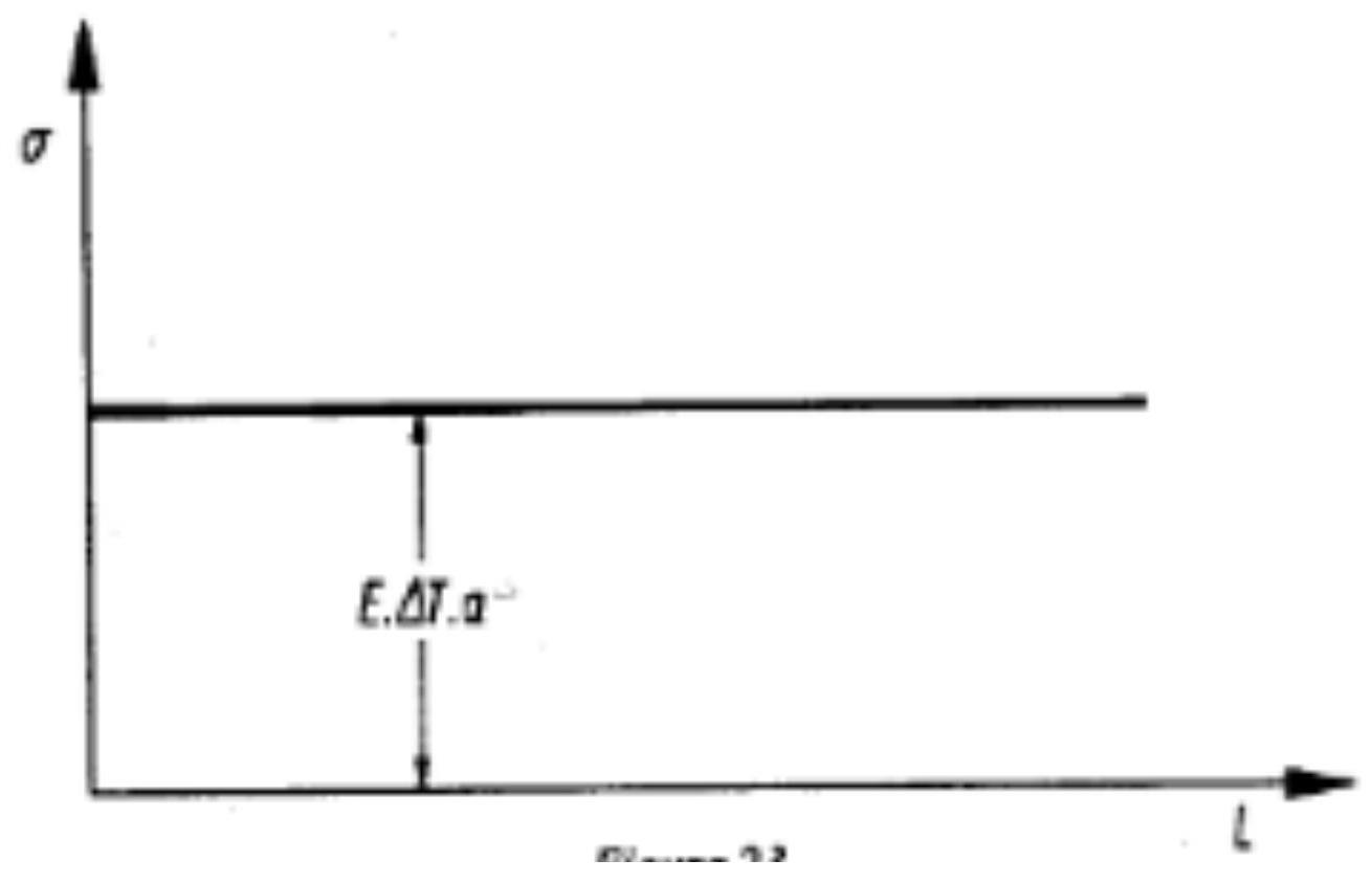
- A value which, as can be observed, is independent of rail length. The stress diagram will be as shown in the figure.
- Assuming a temperature increase of \(30^{\circ} \mathrm{C}\) :
- Taking into account that the surface of a UIC-60 rail is \(7,686 \mathrm{~mm}^{2}\) :
- Which is the force with which the rail end attempts to move or value with which we have blocked its ends to achieve zero expansion, with this temperature variation, and which is evidently important.
However, the rail ends are not blocked, but are free, but the expansion of the continuous welded rail is restricted by the exposed frictions. And as seen previously, the experimentally proven result is that there is zero expansion in the central part of the bar and restricted in zones AC and DB, at the bar ends:
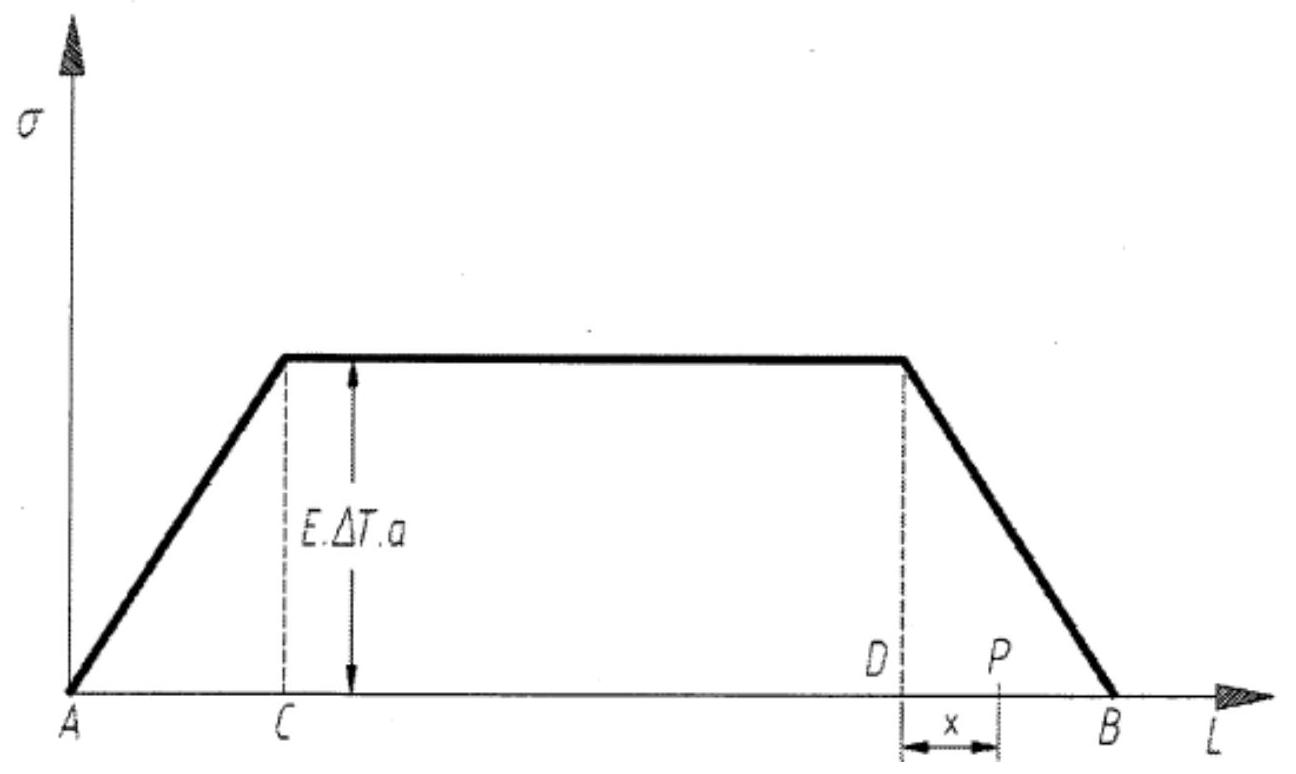
In the central part CD friction remains constant at: \(\sigma=E \cdot \alpha \cdot \Delta T\)
At ends AC and DB, the situation is different: available friction is not sufficient to completely eliminate expansions. That is, in extreme zones, as long as axial force F is greater than the sum of resisting forces opposed by affected sleepers (r), there will be expansions that will necessarily be restricted. The longitudinal extension AC (or DB) is called breathing zone (Z) and represents the region where the transition occurs between the central zone without expansion and the completely free ends:
BREATHING ZONE LENGTHS WITH CONCRETE SLEEPERS IN NEUTRALIZED TRACKS
| \(Z \cdot r=2 \cdot S \cdot \sigma\) | Maximum variation of rail temperature Δt | |||||
|---|---|---|---|---|---|---|
| \(Z \cdot r=2 \cdot S \cdot E \cdot \alpha \cdot \Delta T\) | Rail | Section | \(1^{\circ} \mathrm{C}\) | \(35^{\circ} \mathrm{C}\) | \(40^{\circ} \mathrm{C}\) | \(45^{\circ} \mathrm{C}\) |
| UIC 60 / 60 El | \(7,686 \mathrm{~mm}^{2}\) | \(3.5 \mathrm{~m}\) | 122 m | 140 m | 157 m | |
| \(Z=2 \cdot S \cdot E \cdot \alpha \cdot \Delta T / r\) | UIC 54 / 54 E1 | \(6,934 \mathrm{~mm}^{2}\) | \(3.15 \mathrm{~m}\) | 110 m | 126 m | 142 m |
| RN 45 | \(5,705 \mathrm{~mm}^{2}\) | \(2.6 \mathrm{~m}\) | 91 m | 104 m | 117 m |
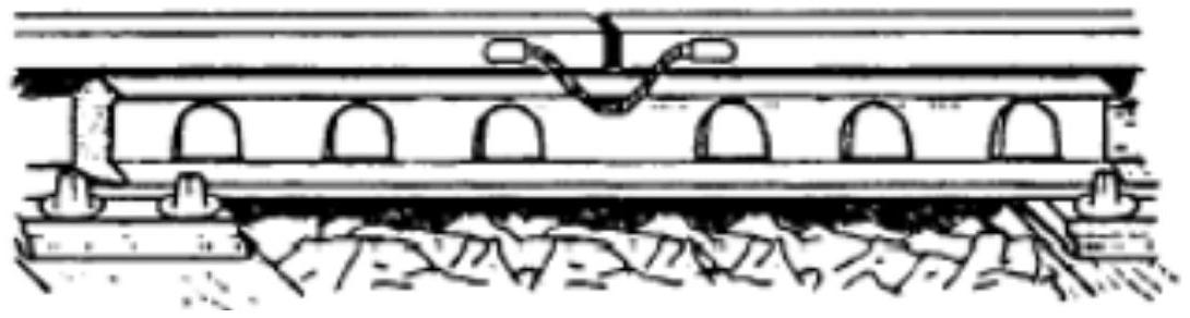
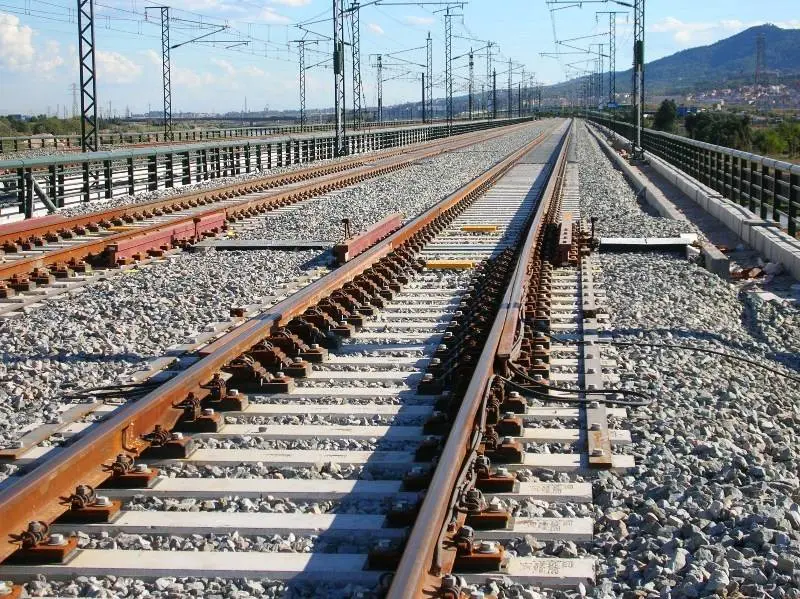
III.3. CWR: Expansion Devices
To understand the behavior of the ends of continuous welded rail, it is necessary to analyze the stress/strain diagram. Let us consider the calculation of the displacement experienced by any point P belonging to the breathing zone Z. If we assume a linear decrease in stresses along this zone:
\[\sigma(x)=\sigma \cdot\left(1-\frac{x}{Z}\right) \rightarrow E \cdot \alpha \cdot \Delta T \cdot\left(1-\frac{x}{Z}\right)\]The stress released at any position x will therefore be:
\[\sigma_{lib}=\sigma-\sigma(x) \rightarrow E \cdot \alpha \cdot \Delta T-E \cdot \alpha \cdot \Delta T \cdot\left(1-\frac{x}{Z}\right) \rightarrow E \cdot \alpha \cdot \Delta T \cdot \frac{x}{Z}\]Consequently, incremental deformation will be:
\[\begin{aligned} \sigma_{lib} & =E \cdot \Delta L / L \rightarrow E \cdot d l / d x \rightarrow E \cdot \alpha \cdot \Delta T \cdot \frac{x}{Z}=E \cdot d l / d x \\ d l & =\alpha \cdot \Delta T \cdot \frac{x}{Z} d x \rightarrow l=\int_{0}^{x} \alpha \cdot \Delta T \cdot \frac{x}{Z} d x \rightarrow l=\alpha \cdot \Delta T \cdot \frac{x^{2}}{2 \cdot Z} \end{aligned}\]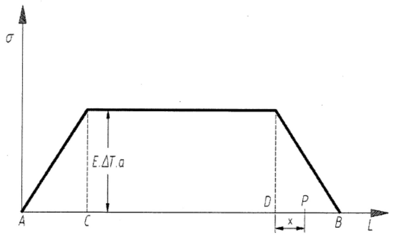
For the final point of the breathing zone where \(x=Z\) on a UIC-60 rail:
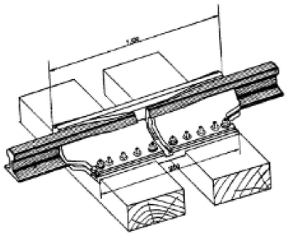
\[\Delta l=\alpha \cdot \Delta T \cdot \frac{Z}{2} \rightarrow \alpha \cdot \Delta T \cdot \frac{3.5 \cdot \Delta T}{2} \rightarrow \alpha \cdot \frac{3.5 \cdot \Delta T^{2}}{2} \quad \begin{aligned} & \Delta T=30^{\circ} \rightarrow \Delta l=17.26 \mathrm{~mm} \\ & \Delta T=60^{\circ} \rightarrow \Delta l=69.05 \mathrm{~mm} \end{aligned}\]The final end of the continuous welded rail is without residual longitudinal stress. For this reason, specialized devices called expansion devices are installed at these critical points, allowing the rail to expand freely without generating excessive internal stresses. As can be observed, calculated expansion values are relatively small. These displacement magnitudes are what the corresponding expansion device must absorb. The device traditionally employed in Spain is the one shown in the figure, capable of absorbing expansions of up to 180 millimeters.
The connection of a jointless track section with another section using short bars or with a turnout that cannot be welded must be made by inserting an expansion device (AD) between both. It is not necessary to install this device if the connection is made between two jointless track sections (CWR) operating under the same neutralization conditions.
III.4. CWR: Stress Neutralization
When continuous welded rail is installed in service on the track, the continuous rail experiences cyclic temperature variations both seasonal and daily, generating internal longitudinal stresses of great magnitude. These stresses can be tensile or compressive, and if their magnitude exceeds certain admissible limits, they can break the rail or cause permanent lateral deformation through buckling and misalignment phenomena.
To reduce extreme values of these thermal stresses and avoid harmful stress states, the rail must be installed in such a way that at a specific intermediate temperature, determined for each geographical zone and called neutralization temperature, longitudinal stress is completely nulled. Neutralization is the operational process of installing the rail precisely in these optimal conditions.
During the stress neutralization process, in addition to nulling global stress, its distribution along the rail is homogenized, eliminating harmful local concentrations.
Stress-Free Temperature
It is defined as the intermediate temperature at which rail longitudinal stress is completely nulled, called stress-free temperature \((t_e)\). A crucial aspect of this parameter is that its value is totally independent of the current ambient temperature of the rail.
The stress-free temperature of a specific rail segment is determined by its exact length, being the dimension it would achieve if it were mechanically free and at that determined temperature. For this reason, when a rail is stretched (for example by hydraulic jacks), the value of this parameter increases, since its greater physical size can be achieved, the rail being without longitudinal stress, only with an additional increase in its temperature.
Neutralization Temperature
For any geographical zone, neutralization temperature is defined as the arithmetic mean of extreme values (maximums and minimums) of rail temperatures recorded over years, increased by an additional 5°C. This magnitude is obtained experimentally by continuous measurement of the temperature of a rail coupon over multiple years in a specific geographical location, or by calculation based on known extreme ambient temperatures. Using maximum recorded in summers and minimum in winters, its value is calculated by:
\[t_{n}=\frac{t_{oMax}+t_{oMin}}{2}+5^{\circ} \mathrm{C}\]In the Spanish Rail Network, neutralization temperatures currently employed are comprised between 25°C and 38°C, varying according to latitude and local climatic conditions.
So that thermally generated longitudinal forces in jointless track rails do not reach excessive magnitudes causing damage to infrastructure, rails must be fixed in such a way that their stress-free temperature is equal, or very close, to the neutralization temperature established for that specific zone. Observe that neutralization temperature depends exclusively on local climatic conditions of the zone and never on current rail installation conditions. On the contrary, stress-free temperature depends totally on the present state of rail installation being completely independent of climatic conditions of the zone. The difference between these two parameters constitutes a quantitative indicator of rail stress state, being higher the greater its numerical value.
Neutralization temperature is a parameter that not only varies from one region to another, but also from one point to another within the same relatively close region. For this reason, it must be considered as a specific parameter at local level. This variability is due to terrain orography also significantly influencing its magnitude.
Neutralizing a rail consists of fixing it with a length equal to that it would have if its temperature were exactly that of neutralization, and simultaneously, distributing its longitudinal stresses homogeneously along its extension.
Considerations Prior to Neutralization
Before performing neutralization operations, several preparatory actions must be executed: In a first phase, elementary bars are installed fixing them to sleepers by fastenings and fishing them to each other. At this moment train circulation can be restored. The next stage consists of carefully adjusting fastening tightening torques and performing all welds of elementary bars with exception of central gaps, which are reserved specifically for subsequent neutralization operations.
If sleepers are not yet completely stabilized (having been placed or moved previously, or by recent ballast replacement), it is necessary to wait for approximately 100,000 tons of traffic to circulate to allow settlement and consolidation of the structure before proceeding to stress neutralization. After reaching this threshold, the operation can be performed.
Important Operational Considerations
- At the moment of installing the track, it is convenient, to facilitate subsequent neutralization, to do so with fixation temperature below or equal to projected neutralization temperature.
- The track will be neutralized only when sufficiently stabilized. A track is considered stabilized when its constitutive elements obtain maximum possible resistance to external forces tending to deform it.
- Level crossings and bridges without expansion device must not be located in the breathing zone of the continuous welded rail.
Neutralization Techniques and Procedures
Neutralization of stresses in rail installed on track is performed working on two semi-bars separated by a central gap of appropriate dimension, having their ends constituted by predetermined fixed points. The two semi-bars will be welded together when their length is exactly what they would have at neutralization temperature, a length achieved by distinct specialized techniques:
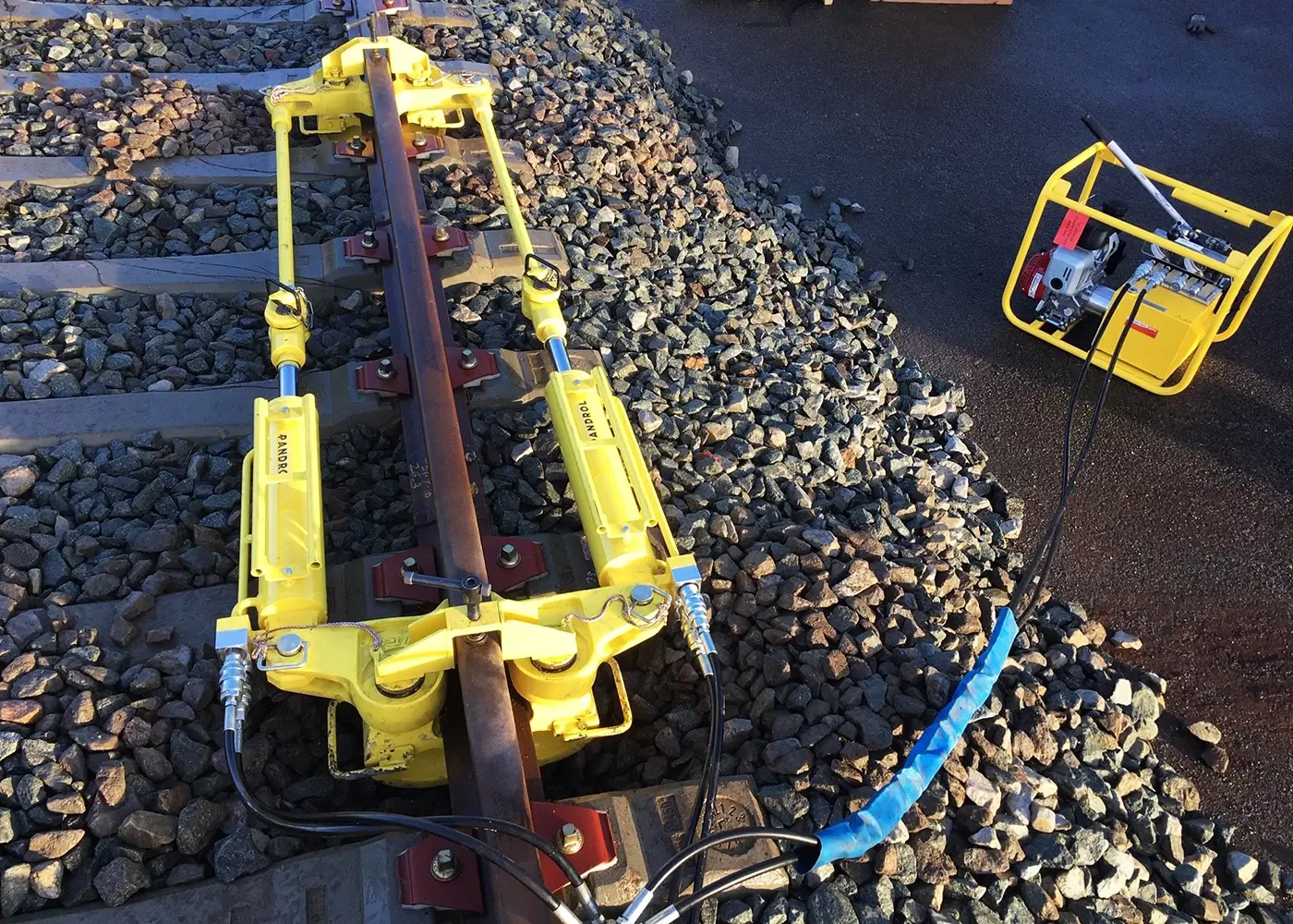
Provisional Long Bar Traction Method: The rail is stretched by high-capacity hydraulic jacks to reach the exact desired length. The main advantage is that it can be executed at any rail temperature provided it is lower than neutralization temperature. The main drawback is that it presents significant execution difficulties in small radius curved sections.
Rail Solar Heating Method: Exploits natural heating experienced by rail by solar radiation. One must wait patiently for its temperature to sufficiently approximate neutralization temperature, either increasing during the day or reducing according to climatic variations. Advantages include no special apparatus needed and can be performed even in small radius curves. Disadvantages are that direct measurement of rail temperature is imprecise during heating, especially on sunny mornings with variable clouds, and knowledge of forecasted thermal evolution is required to choose the ideal moment for the operation, potentially meaning significant time losses waiting for suitable thermal conditions.
The complete rail neutralization process consists of multiple operations, most of them common to both main techniques. The fundamental difference between techniques resides in the specific mode of achieving necessary rail deformation to acquire correct length. Operational stages both techniques require are:
- Choice of length to release
- Constitution of reference fixed points
- Precise measurement of rail temperature
- Release and homogenization of stresses
- Cutting of rail, controlled loosening of fastenings, mallet tapping with rail on rollers
- Marking of rail and sleepers (in traction method only)
- Exact dimensioning of central gap
- Rail tensioning (in traction method)
- Controlled tightening of fastening
- Welding of the two semi-bars
- Finally, all data of the operation performed will be noted to constitute the official Neutralization Act
III.5. CONSTITUTION OF FIXED POINTS
Constitution of fixed points is a fundamental operation for orderly realization of the neutralization process. Fixed points serve as invariant geometric references ensuring that traction or heating operations are applied precisely, without destabilizing adjacent track sections.
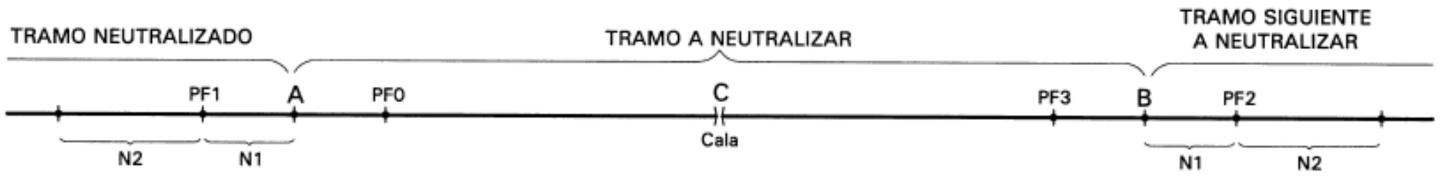
In the previous scheme are identified:
- PFO: Fixed point of preceding section
- PF1 and PF2: Fixed points of section to be neutralized
- PF3: Fixed point of following section to neutralize
The number of sleepers affected by constitution of fixed points varies according to method employed:
| NEUTRALIZATION | \(\mathrm{N}^{\circ}\) OF SLEEPERS | |
|---|---|---|
| N1 | N2 | |
| BY TENSORS | 20 | 60 |
| BY SOLAR HEATING | 10 | 30 |
III.6. TENSIONING: CHECK MARKS
During tensioning operation by traction, it is essential to have check marks allowing verification of real rail displacement and confirmation that exact required length has been reached.

CWR: Stress Neutralization
III.7. Rail Welding
Terminology and Definitions
Elementary bar is the name given to rails obtained directly from the industrial rolling process. A typical standard length of elementary bars is 18 meters, a limitation imposed by capacities of rolling mills and transport requirements.
Workshop bars are those obtained by welding performed in specialized workshop or storage yards, where several elementary bars are joined to be subsequently transported to the definitive placement site at the work. Historically, the Spanish network (RENFE) used to adopt workshop bars of 288 meters length (corresponding to 16 × 18 meters). In principle, length of these workshop bars should be as large as possible from economic and operational point of view, but this dimension is practically limited by available rail and road transport restrictions.
The union of several workshop bars, performed in situ after they have been placed in their definitive position at work, finally constitutes the continuous welded rail, which is the jointless track infrastructure entering service.
Welding Procedures
There are several alternative welding procedures available in railway technology. Habitual industrial practice is to use electric flash butt welding in workshop facilities, where robust equipment and controlled conditions are available. Conversely, at the work (in field), the procedure preferably used is aluminothermic welding, offering significant operational advantages in field conditions.
- Elementary bar is the name given to rails obtained directly by rolling, 18 m is a usual length for them.
- Workshop bars are those obtained by welding in workshop or yard, of several elementary bars to be then transported to placement site of work, RENFE used to adopt \(288 \mathrm{~m}(16 \times 18)\). In principle length of these workshop bars should be as large as possible, but is limited by transport.
- The union of several workshop bars, in situ, after placed at work, constitutes continuous welded rail.
- Several welding procedures exist; usually in workshop procedure called electric flash butt welding is used and at work aluminothermic welding.
III.7.1. - Aluminothermic Welding:
Aluminothermic welding is a highly exothermic oxidation process based on chemical reaction between metallic aluminum and ferrous oxide (iron trioxide), producing iron in liquid state enriched with special alloying elements improving its mechanical properties. Rail ends fuse completely and combine intimately with filler material coming from exothermic reaction, creating a monolithic union.
Main Characteristics:
- Process relatively easy to execute compared to other techniques
- Moderate operational cost compared to specialized equipment
- Material contribution: filler metal generated from reaction does not possess exactly same metallurgical characteristics as rail steel, potentially requiring subsequent treatment
- Process essentially manual, requires approximately 20 minutes per weld, allowing rate of 2-3 welds per hour
- Generates residual internal stresses due to different cooling between rail web and head/foot, requiring post-weld heat treatment
Execution Process:
- Carefully align the two rails to be welded
- Place containment molds around ends to act as formwork
- Slightly preheat rail ends
- Fill crucible with reagents (aluminum powder and iron oxide)
- Initiate exothermic reaction controlledly
- Uncap lower part of crucible to eliminate decanted steel and surplus material (approximately 10 seconds after reaction finished)
- Cool weld controlledly for three minutes
- Remove molds and deburr excesses
- Grinder: final polishing with motor grinder to obtain correct geometry
III.7.2. - Electric Welding:
Electric flash butt welding constitutes a totally different process based on Joule heating and controlled plastic deformation. It is performed both stationary in specialized workshops and by mobile welding machinery in field. The mechanism is unique: it is the rail material itself that heats and welds by passage of high intensity electric current through contact zone. For this reason, resulting weld is composed entirely of original rail steel, without external material contribution.
Main Characteristics:
- No external material contribution (autogenous welding with rail steel)
- Totally automated control by computerized systems
- Superior operational speed: allows 6-10 welds per hour
- Loss of approximately 4 centimeters of rail material per weld occurs (upset metal)
- Requires specialized and specific machinery to perform in the work itself
- Very high initial investment cost, although operationally efficient at large scale
- Superior metallurgical quality with fewer residual stresses than aluminothermic welding
Execution Process:
- Progressively bring two rails to contact
- Align and level ends perfectly
- Apply high intensity electric current (approximately 35,000 amperes at 5 volts)
- Allow controlled progressive approach as fusion occurs
- Apply upset force (forging) when plasticity temperature is reached
- Rough deburring with special chisels
- Fine grinding to obtain correct geometry
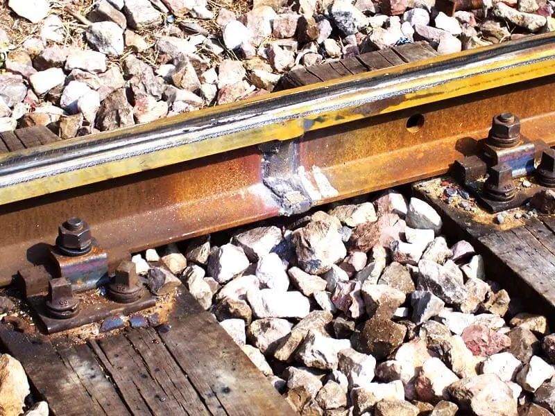
Weld Defect Analysis:
Operational experience has documented diverse types of defects that can appear in rail welds, requiring analysis and repair:
Among documented defects we find:
- Breaks caused by Aluminothermic Welding (inferior residual strength)
- Breaks by Flash Butt Welding (alignment defects or incorrect parameters)
- Corrosion (insufficient protection or especially aggressive environment)
- Squats (rail-wheel contact defects propagating inwards)
- “Shelling” (detachment of surface layers)
- Head Checks (surface cracks in rail head)
- Material Fatigue (progressive breaks under cyclic loads)
- Material Defects (intrinsic metallurgical defects)
- Curve Defects (stress concentration in curved geometry)
- Rail End Errors (defects in ends of elementary bars)
- Others (miscellaneous unclassified defects)
Review Questions
What are the main functions of fastening systems?
To keep rail and sleeper united, absorb dynamic loads, preserve geometry/track gauge, prevent rail overturning, and provide electrical insulation.
What main maintenance difference exists between elastic clamp fastenings (like RN) and clip fastenings (like PANDROL)?
Clip fastenings (PANDROL) have no threaded elements and hardly require maintenance (tightening), while clamp ones (RN) need periodic retightening of nuts.
What is the neutralization temperature in a Continuous Welded Rail (CWR)?
It is the intermediate temperature (mean of extremes + 5°C) at which the rail is fixed so that its longitudinal stress is zero, minimizing risks of buckling or breakage due to thermal variations.
What is the function of expansion devices in jointless track (CWR)?
To allow free expansion of long bar ends (breathing zone) without generating excessive internal stresses, absorbing thermal displacements.
What advantages does electric flash butt welding offer over aluminothermic welding?
Electric welding is autogenous (without foreign filler material), has superior metallurgical quality, is automated and faster, although it requires heavy machinery.
Bibliography
- Díaz de Villegas, J.M. (2003) Ferrocarriles. Apuntes de clase. E.T.S. Ing. Caminos, Canales y Puertos Santander.
- García Álvarez, A. (2022) Manual de ferrocarriles. El sistema ferroviario español. Ed. Garceta.
- Lichtberger, B. (2011) Manual de vía. Infraestructura, superestructura, conservación, rentabilidad. Eurail Press.
- Villaronte Fernández-Villa, J.A. (2009) Ingeniería y Tecnología Ferroviaria - Tecnología de la vía. Delta Publicaciones.
- Adif: normativa técnica: http://descargas.adif.es/ade/u18/GCN/ NormativaTecnica.nsf