Ballastless Railway Superstructure Systems: Slab Track Technology and Applications
Table of Contents
Chapter I Introduction
Slab track represents an innovative alternative to traditional railway superstructure systems. It can be characterized as a track system in which the conventional ballast has been replaced by one or more layers of structural materials of varying stiffness, comprising concrete layers, asphalt bases, or metallic supports.
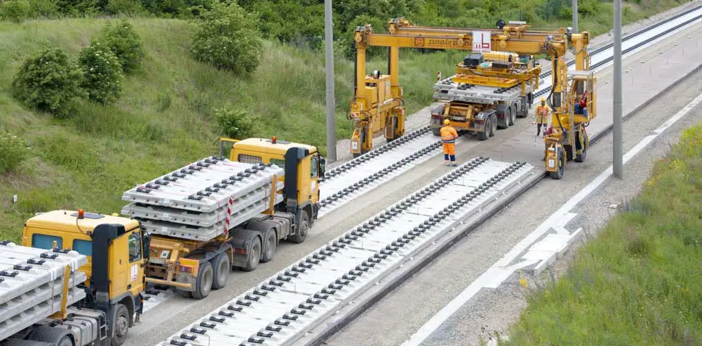
The construction solutions for the bearing slab can be executed either by in-situ concreting or by using precast elements assembled at the construction site. In the case of asphalt bases, construction proceeds by continuous compaction of the material during its placement. It should be noted that in certain applications, in addition to replacing the ballast, traditional sleepers are also dispensed with, integrating their functions into other system components.
 In this configuration, all functions originally performed by the ballast and sleepers must be assumed by the various components that make up the slab track structure.
The fundamental purpose of implementing slab track systems lies in achieving high-quality infrastructure through mechanisms that allow for significantly reducing operational expenses and the times required for maintenance tasks. By decreasing the number of necessary interventions, the availability of facilities for actual transport operation is increased.
Although this approach requires considerable initial capital investments, it is important to highlight that conservation costs represent between 15% and 20% of total operating costs. To illustrate the relevance of this issue, consider the case of the Bilbao Metro, where 85% of annual track repairs are concentrated in segments with ballast, even though these represent only 39% of the total network extension. This disparity underscores the need to evaluate these solutions from a long-term amortization perspective, where cumulative maintenance savings justify the higher initial investment.
Slab track systems are composed of a series of elements that interact in an integrated manner to provide structural support and proper functioning of the railway superstructure.
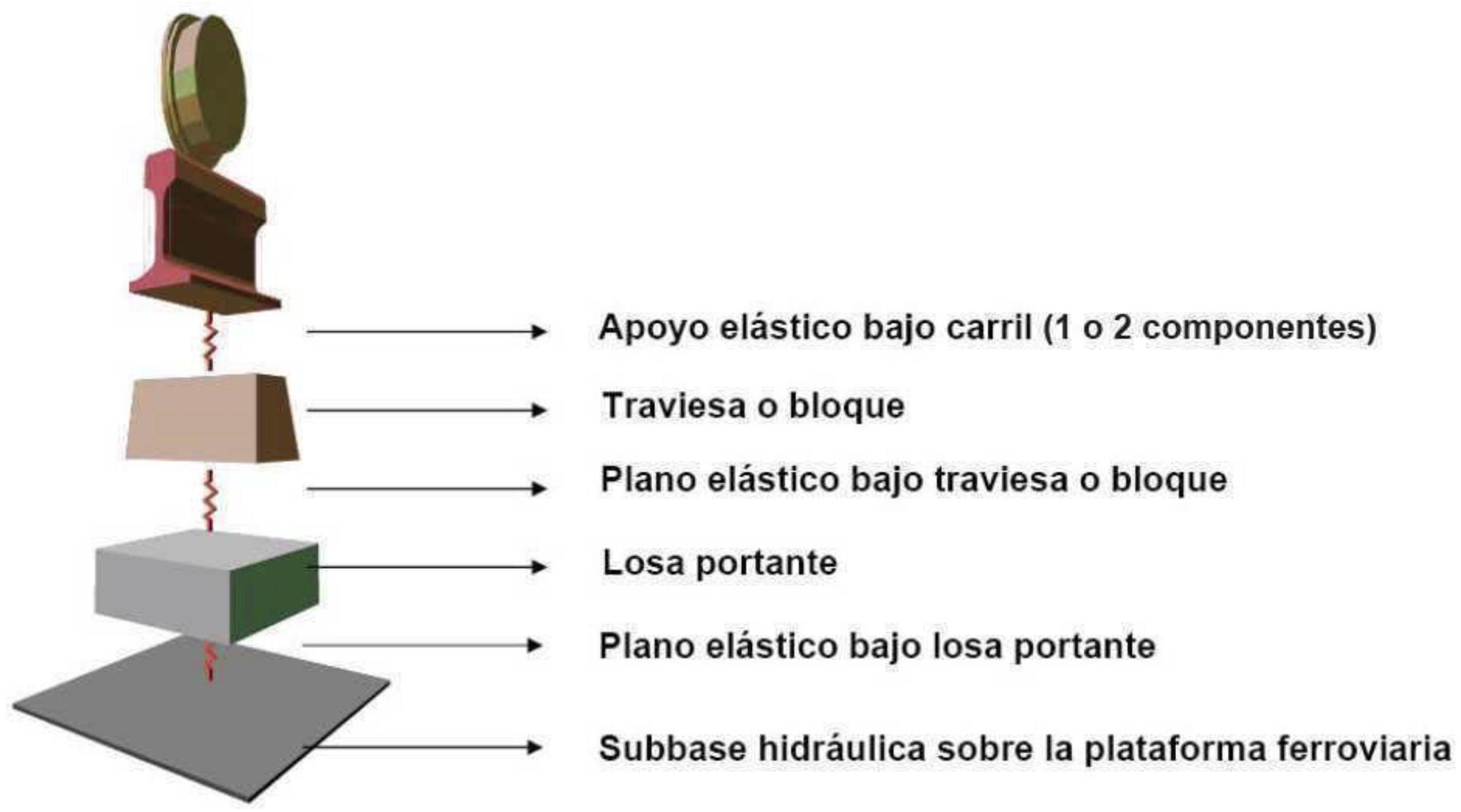
Note: all parts can be dispensable except the elastic support under the rail and the bearing slab.
I.1. Background
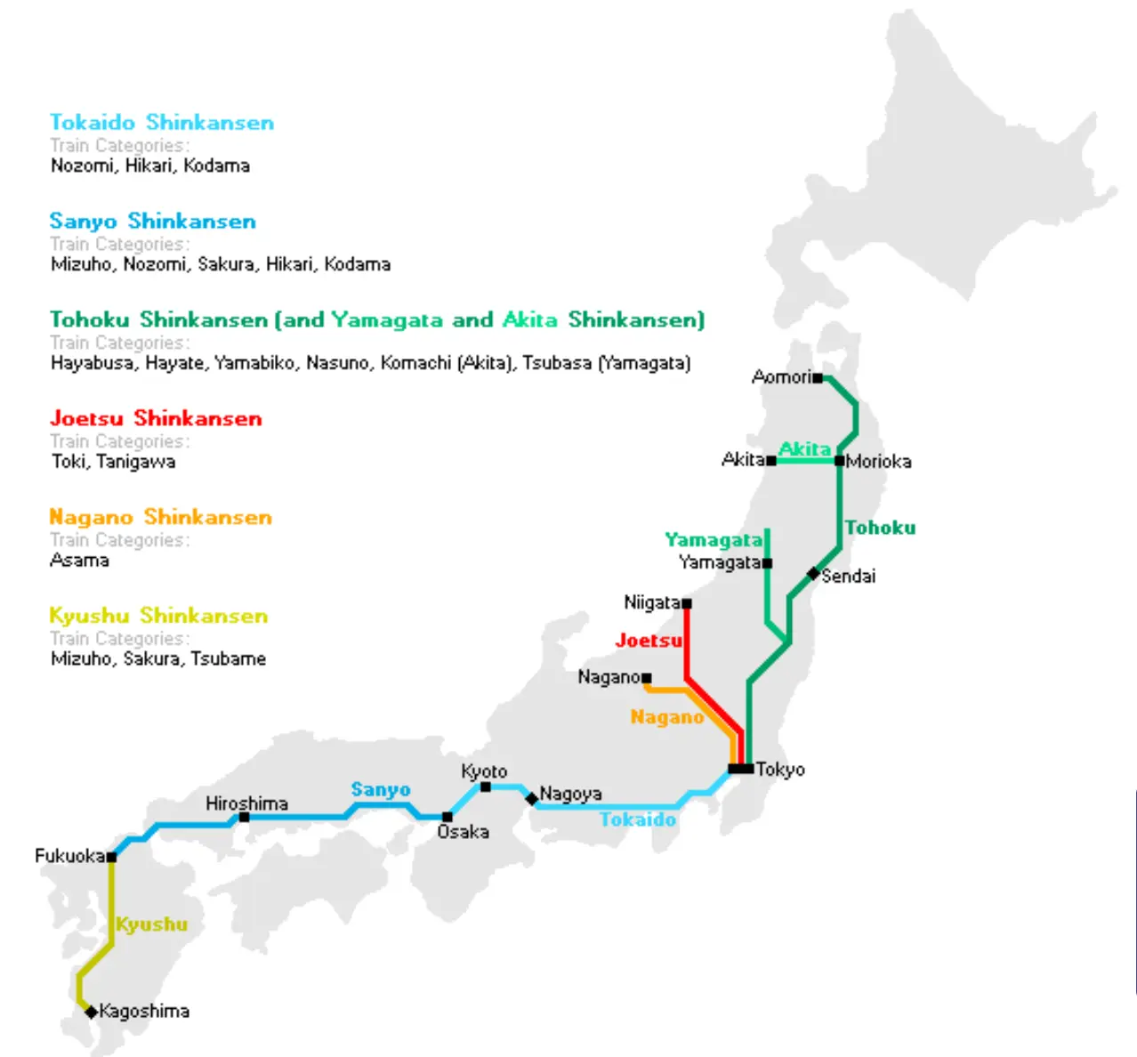
The historical development of slab track technology constitutes a gradual innovation process spanning more than a century. The first trials with this technology were carried out in Japan in 1924, during a time when railway engineering was exploring alternatives to traditional construction methods.
In 1972, Germany made a significant contribution with the development of the Rheda system at the station bearing its name, introducing a configuration where precast sleepers are interconnected by longitudinal reinforcement and anchored within a reinforced concrete slab supported on two layers of rigid sub-bases. During the 1970s, France and Great Britain independently developed the Stedef and PACT systems, respectively, thus expanding the range of available solutions.
The 1980s marked an important turning point, characterized by the intense theoretical and experimental development of various slab track systems, which began to be implemented in multiple operational contexts such as commuter lines, viaduct structures, tunnels, metropolitan transport systems, and station complexes. During the 90s, the focus shifted towards adapting these systems for high-speed applications, a decision that was pioneered by Germany in the construction of its ICE lines.
In parallel, Spain established specialized working groups to investigate and develop its own solutions in this field.
I.2. Benefits
- Slab track offers:
- Mechanical Behavior: Great uniformity of vertical stiffness, strong lateral resistance, and better transmission of stresses to subgrade layers (between 1 and \(3 \mathrm{~N} / \mathrm{cm} 2\) )
- Durability: Longer service life of the surface or bearing slab (60 years) and improvement of that of other elements (rail and sub-base) compared to ballasted track.
- Maintenance: Preservation of good and practically invariable track geometry over time at almost any operating speed. Lower costs throughout the entire service life. Reduces the need for daily maintenance intervals (windows) and therefore increases time availability for pure operation (train circulation).
- Construction Height and Gauge: Significant decrease compared to ballast.
- Passability: Transitability with pneumatic-tired vehicles is possible in some cases.
- Cleanliness: Aesthetic improvement and effectiveness of fitted elements.
Chapter II Systems
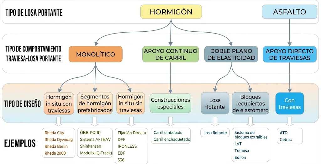
In this chapter, the main slab track systems developed internationally are presented. Each solution responds to specific needs of the context in which it is applied, considering factors such as operating speed, geotechnical conditions, maintenance requirements, and construction constraints. The classification presented below shows the diversity of approaches adopted by different engineers and manufacturers to solve the challenge of replacing ballast while maintaining or improving track performance.
II.1. In-situ Concrete Embedded Sleeper Systems
II.2.1. RHEDA System
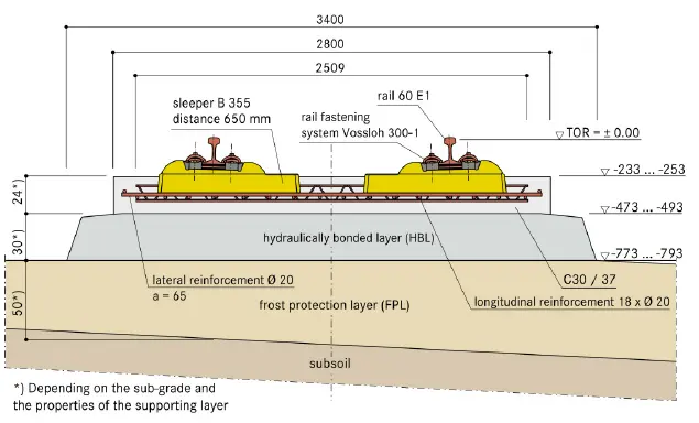
The RHEDA system represents one of the most widely used approaches today. Its conception is based on the integration of precast sleepers into an in-situ concrete matrix, providing a highly monolithic structure. The Rheda Dywidag variant constitutes an alternative option that introduces refinements to the original design.
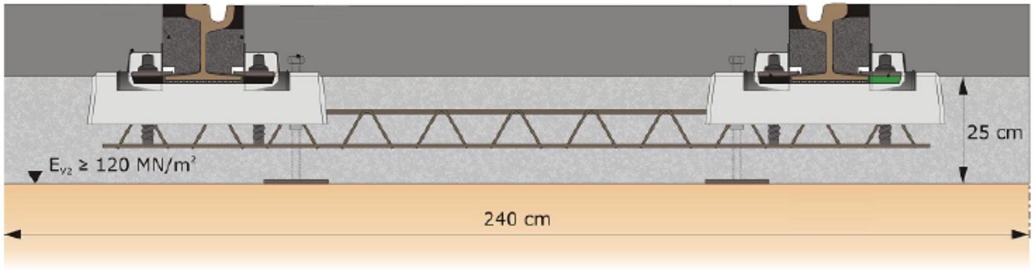
In the standard RHEDA 2000 configuration, monoblock sleepers are embedded within a reinforced concrete slab, which in turn is confined within a support trough. This arrangement eliminates the joint between the concrete of the cover slab and that of the trough, significantly improving durability by preventing medium-term cracks that would derive from relative movements between these components. The elimination of this structural discontinuity also enables a significant reduction in the total construction height.
A thin bituminous layer is placed between the support trough and the slab containing the sleepers. The trough itself is built of reinforced concrete with expansion joints strategically positioned to control the appearance of cracks, and rests on a layer of cemented granular material 30 centimeters thick.
Within the family of RHEDA systems, there are multiple variants adapted to different application contexts. The City model has been specifically developed to support tram traffic, maintaining the monolithic construction of the slab and incorporating bi-block concrete sleepers. The MRT system, intended to serve commuter lines and metropolitan transport, represents a lightened version of the RHEDA 2000, dispensing with the support trough while maintaining the monolithic integration between sleeper and slab.
 Rheda 2000
 Rheda City.
Rheda City with embedded road surface asphalt
 Rheda Dywidag
II.2.2. In-situ Concrete with Sleepers: ZÜBLIN System
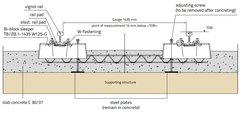
The Züblin model represents an alternative approach to the RHEDA methodology. In this solution, concrete is not poured between sleepers of a previous structure, but rather the sleepers are integrated directly into the fresh concrete of the main slab during its in-situ concreting. This process requires specially designed equipment that allows concrete sleepers to be inserted under pressure while vibrating the fresh material, ensuring their correct position and penetration into the mixture.
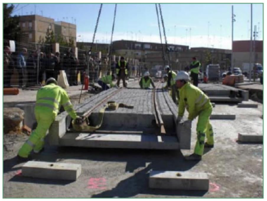
ΙΙ.3. Precast Concrete Segments
II.3.1 SHINKANSEN System
- The system consists of a precast slab that rests on a concrete base. The development of precast slabs has undergone a significant technological evolution. In its origins, conventional reinforced concrete was used to manufacture large-dimension slabs; however, modern technology has incorporated prestressed concrete which allows a significant reduction in the weight of components while maintaining their structural properties.
Variability in slab design responds fundamentally to two parameters: their geometric dimensions and the connection strategy with the support base. Type M slabs present dimensions of 2.3 meters long by 2.4 meters wide, being supported at discrete points by stoppers and elastomeric joints. Type A slabs, of larger dimensions (4.95 meters long by 2.34 meters wide), are characterized by having continuous contact with the base through a cold mortar film, resulting from the combination of asphalt bitumen and cement.
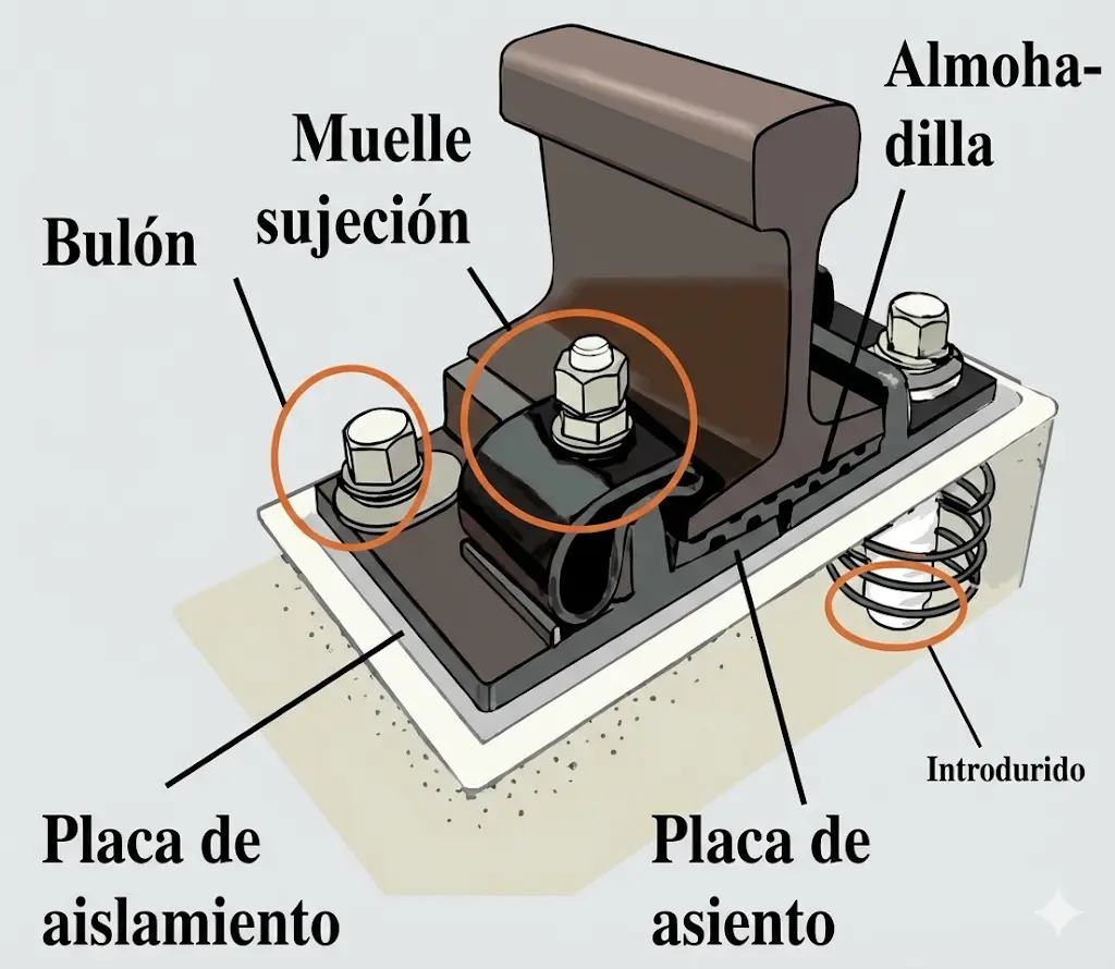
The interface between the base and each precast slab is completed with the introduction of self-leveling mortar, which provides isolation from the base soil and significantly improves durability against repeated freeze-thaw cycles. The positioning of the slabs is achieved by fitting them between vertical concrete cylinders, called “stoppers”, which emerge from the base. These elements fulfill multiple structural functions: they provide connection between contiguous slabs, link each slab with the base, and being coated with resin mortar, act as thermal expansion elements for the concrete. The rail is mounted on a seat pad located on a support plate that is directly fixed to the slab.
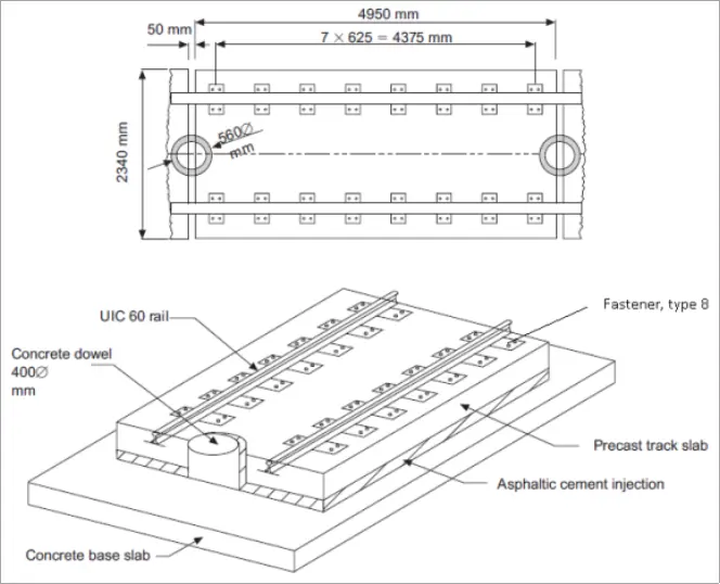
Slab Track Structure
II.3.2. ÖBB-PORR System
The PORR Slab Track System (specifically the Austrian Slab Track Austria or STA system) is one of the most widely used ballastless track designs in the world. Developed through a partnership between PORR and Austrian Federal Railways (ÖBB), it’s a high-performance alternative to traditional sleepers and gravel.
II.3.2.1. Core Components and Design
The system is built on the principle of unbonded construction, which allows for high precision and easier maintenance than monolithic concrete pours.
- Precast Concrete Slabs: The heart of the system is a reinforced concrete base plate, manufactured in a factory to ensure extreme structural integrity and surface smoothness.
- Elastic Layer: A specialized elastic coating (usually an elastomer) is applied to the bottom of the slab. This acts as a vibration damper and creates a defined separation between the slab and the self-compacting concrete (SCC) poured beneath it.
- Tapered Cones: The slabs feature large, tapered openings. During installation, SCC is pumped into these holes, anchoring the slab to the hydraulic bonded layer (HBL) below.

II.3.2.2. Key Advantages
The PORR system is favored for projects like the HS2 in the UK and various Alpine tunnels for several reasons:
- Extreme Precision: Because the slabs are precast, the rail fastenings are positioned with millimeter accuracy before the slab ever reaches the construction site.
- Rapid Installation: The “plug-and-play” nature of the slabs speeds up the construction timeline compared to traditional ballast, which requires extensive tamping.
- Low Maintenance: Unlike ballast, which shifts and breaks down over time, slab track remains stable for decades, significantly reducing long-term operational costs.
- Easy Replacement: If a slab is damaged, the “unbonded” design means it can be lifted out and replaced without destroying the entire track bed.
II.3.2.3. Where It’s Used
- High-Speed Lines: Where stability at 300+ km/h is non-negotiable.
- Tunnels: Where the limited space makes traditional ballast maintenance nearly impossible.
- Mass Transit: Urban environments that require heavy vibration dampening to protect nearby buildings.
II.3.3. Precon Aftrav System
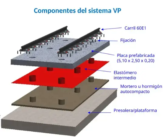
The VP-AFTRAV precast slab track system, manufactured by Precon (of the Molins Group), is an advanced technical solution designed specifically for high-performance railway lines, especially in complex sections such as viaducts, tunnels, and high-speed zones.
Unlike traditional in-situ concreting systems, this system is based on the use of precast prestressed concrete slabs, which guarantees industrial quality control and much faster execution on site.
II.3.3.1. Technical Characteristics of the Slab
- Standard Dimensions: Slabs usually have a length of 5.10 meters, a width of 2.50 meters, and a depth (thickness) of about 20 cm.
- Prestressed Concrete: Unlike conventional reinforced concrete slabs, these slabs are prestressed in both directions (longitudinal and transversal). This prevents flexural cracking and drastically improves system durability.
- Weight: Each slab weighs approximately 8 tons, which allows for handling and transport with standard railway construction machinery.
II.3.3.2. System Components
The AFTRAV system consists of a multi-layer structure:
- Base: A concrete sub-base or the viaduct deck itself.
- Leveling Layer: Self-compacting concrete or special mortars are used to bond the precast slab to the base and ensure exact elevation.
- Fastenings: Incorporates fastening systems (usually Pandrol brand) that are anchored directly to the slab. These fastenings allow high regulation (up to +26 mm vertically and ±10 mm horizontally), fundamental for correcting deviations after assembly.
- Elastic Elements: Pads are included under the rail or under the slab itself (depending on the specific design for vibration control) to provide the elasticity that ballast provides in conventional track.
II.3.3.3. Main Advantages
- Suitability for Viaducts: It is the reference system for long bridges (such as those of the Madrid-Galicia HSL or the Pajares Bypass), as it allows excellent dynamic behavior and reduces dead loads compared to ballast.
- Low Maintenance: Being a rigid and prestressed system, leveling and alignment needs over time are minimal.
- Speed of Execution: Assembly is almost like a “puzzle”. Slabs arrive finished from the factory and only require positioning, leveling, and pouring of the bonding concrete.
- Adaptability: Special pieces exist for manholes, shorter slabs, or triangular slabs for skewed bridges.
II.3.3.4. Relevant Applications
This system has been a protagonist in recent Spanish railway engineering:
- Madrid-Galicia HSL: Installed on numerous viaducts in the Pedralba-Ourense section.
- Pajares Bypass (Asturias): Used to ensure track stability in extreme geological and structural conditions.
II.3.4 Bogl
Both the Bögl (Max Bögl) and PORR (Slab Track Austria) systems seem similar to an untrained eye, but they differ significantly in how the slabs are connected and how elasticity is integrated into the track.
| Feature | Bögl (FFB) | PORR (Slab Track Austria) |
|---|---|---|
| Origin | Germany (Max Bögl) | Austria (ÖBB/PORR) |
| Slab Connection | Longitudinal coupling (force transmission joints) to form a continuous ribbon. | Independent slabs (separated by small gaps) without rigid longitudinal coupling. |
| Elasticity | Provided mainly by the rail fastening system (elastic pads). | Multi-layer: Elasticity in the fastening system plus an elastic layer under the slab. |
| Base Support | Slabs sit on a layer of cement-bitumen mortar. | Slabs rest on self-compacting concrete (SCC). |
| Structure | Biaxially prestressed concrete. | Reinforced or prestressed concrete with integrated “pockets”. |
II.4. In-situ Concrete Segments without Sleepers
This system, which bears similarities to Japanese approaches, was developed as an alternative for contexts where greater flexibility in design is sought. The structure is based on a concrete platform acting as a foundation slab, executed in situ with expansion joints spaced every 30 meters. On this base, and mediated by a 5-centimeter thick bituminous mortar layer, prestressed concrete slabs are placed with a thickness somewhat less than in the SHINKANSEN system (15 centimeters compared to 16-22 centimeters of the Japanese system).
To complete the track cross-section, it is filled with ballast to reconstitute the lateral shoulders. In the particular case of its application in tunnels, the section is completed by precast elements placed in the inter-track and on the sides, allowing for obtaining a running surface suitable for rubber-tired vehicle traffic.
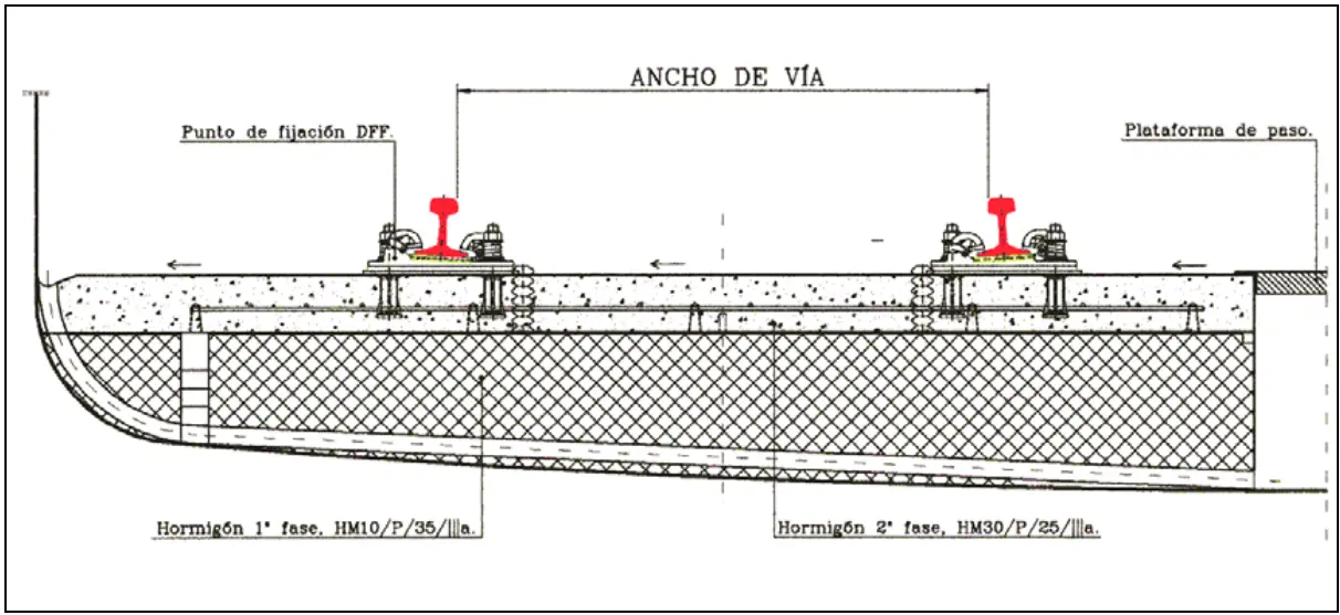
II.3. In-situ Concrete Segments without Sleepers: Direct Fastening
This solution is based on integral in situ concreting of the track, combined with a direct rail anchoring system. The distinctive feature of this approach is that most of the system’s rigidity comes from the concrete structure, while the elasticity necessary for damping and accommodating deformations is provided completely by the fastening system.
The structure consists of two layers of concrete: a lower layer of low-strength concrete acting as a base, upon which a second layer of higher-performance reinforced concrete is executed, built without expansion joints. The rail rests on an elastomeric plate that provides the elastic interface between the rail and the rigid structure. The fastening system is made up of multiple integrated components: a support anchored to the concrete using epoxy resin mortar, an elastic clip that presses the rail, and an insulating element that includes a casting plate and a nylon sleeve wrapping the clamp, ensuring controlled contact with the rail foot.
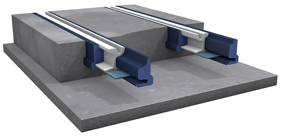
II.4. Embedded Rail Systems
In these systems, the rail operates without discrete supports on sleepers, but instead is supported continuously along its entire length on the bearing structure. This configuration eliminates the intermittent bending that the rail suffers between discrete supports, significantly reducing fatigue stresses in it. Consequently, a substantial improvement in load distribution is produced, both in static and dynamic conditions.
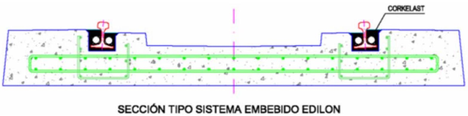
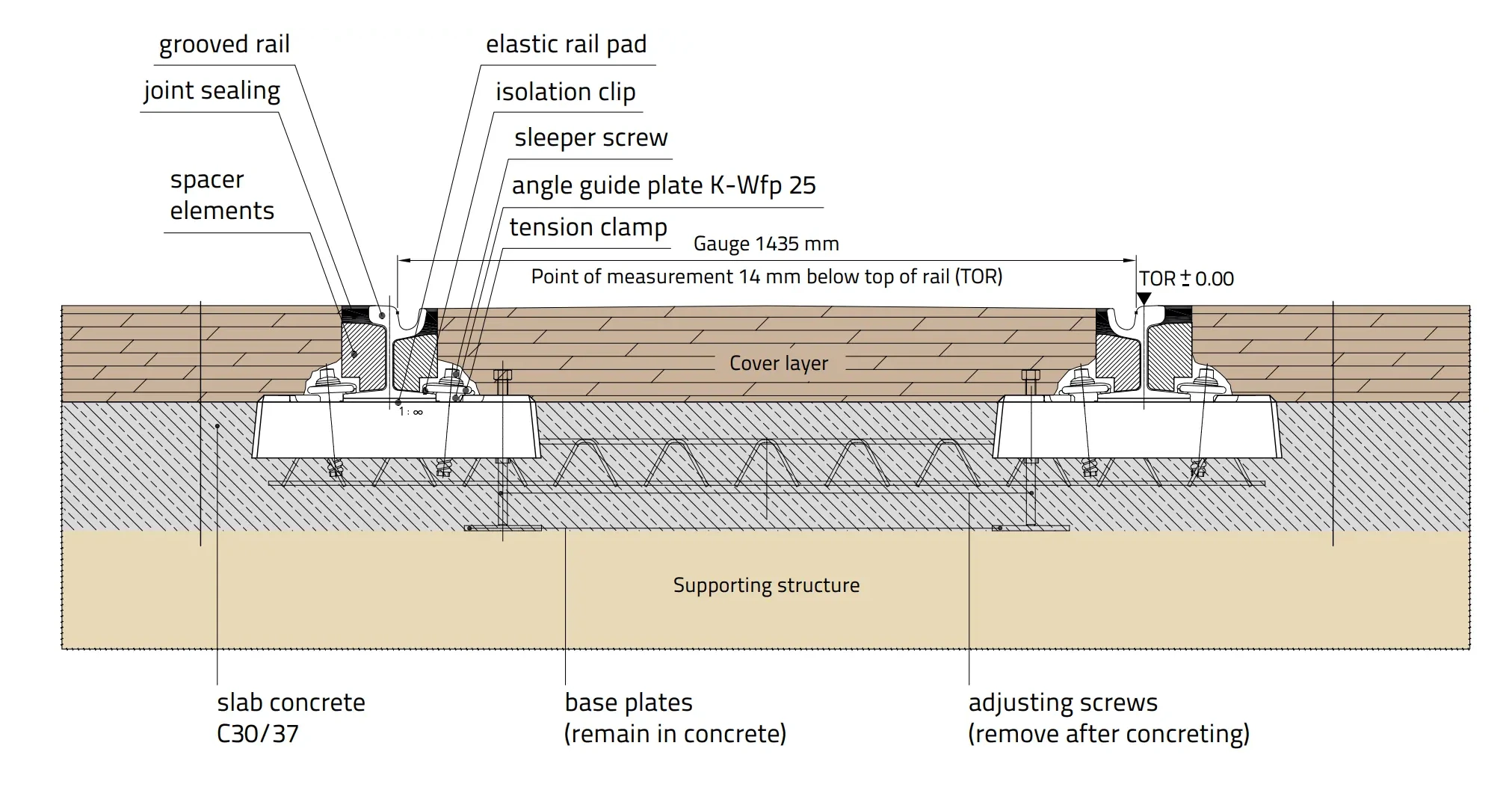
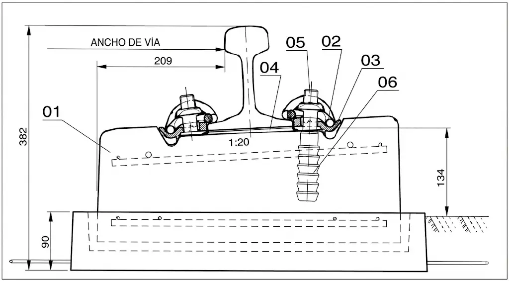
The fundamental concept consists of a reinforced concrete slab on which longitudinal grooves are executed. The rail is introduced into these grooves and fixed by wooden wedges that maintain the specified inclination (typically 1/20). Subsequently, the rail is completely embedded in an elastomeric material that provides both fixation and necessary elasticity and damping for its correct functioning during operation. For the purpose of optimizing the use of elastomeric material, PVC tubes are inserted on both sides of the rail web.
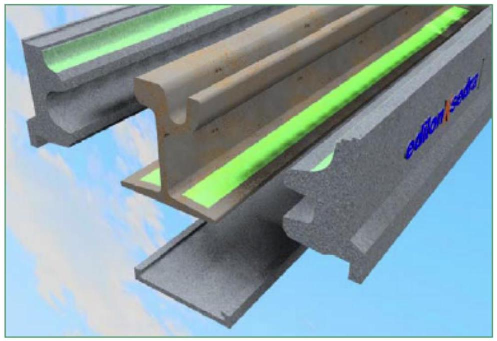
The diversity of systems available in this category derives from variations in the dimensions of the constituent components, including the rail seat plate, the concrete block, and the elastomeric material used. There are multiple commercial variants such as LTV, Coopsette, and Walo, some of which may even incorporate RS sleepers dispensing with the central metal tie bar. The most recognized commercial system is the Edilon, famous for its specific elastomeric composition incorporating cork particles, which is poured in liquid state and solidifies adopting the required shape. This system has gained wide acceptance for the ease it provides during its installation on site.
In the Edilon system, the elastomer (known as Corkelast) is poured in liquid form into the concrete tray on which the block rests. The dimensions of the fixing wedges are modulated according to the expected traffic on the line, and the elastomer presents adjustable flexibility according to the type and level of traffic it must support. Although diverse types of rails can be used (including grooved rails and Vignole profile), most applications employ grooved rails.
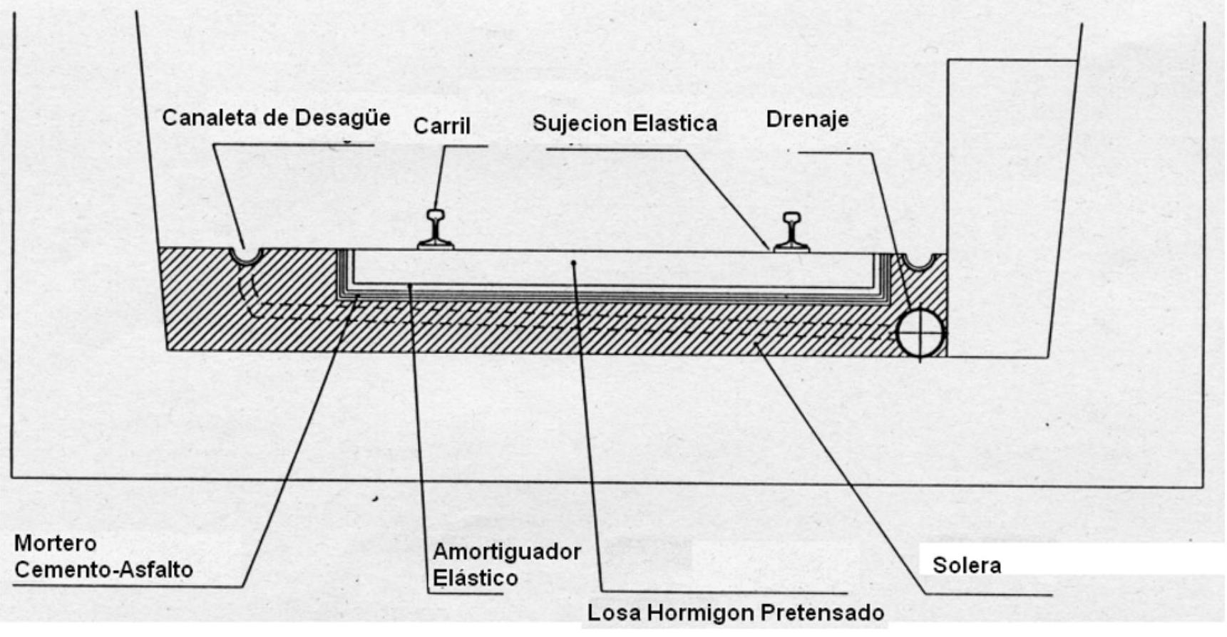
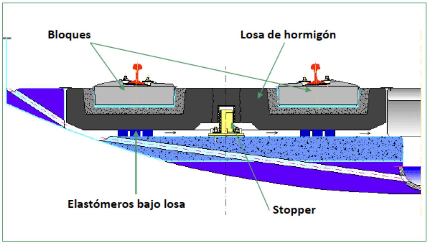
II.5. Floating Slab: FST
This system represents a solution oriented towards the minimization of transmitted noise and vibrations. The structure consists of a post-tensioned slab resting on four circular elastomeric support points, being simultaneously laterally confined by concrete stops. The dimensions of the slabs are relatively small (1.25 meters long by 2.85 meters wide), with a minimum thickness of 20 centimeters. Two stops, either of steel or concrete, are arranged on the upper part of each slab to prevent possible derailment situations.
Rail positioning is performed with precision in its correct location on the support slab, subsequently effecting its fixation in that position using specifically designed fastenings. The correct rail support level is achieved by pads located in the fastenings, with a typical thickness of 12 millimeters. A differentiating aspect of this system is that the fastenings fix the rail laterally but do not restrict its longitudinal movements, thus allowing for thermal accommodation.
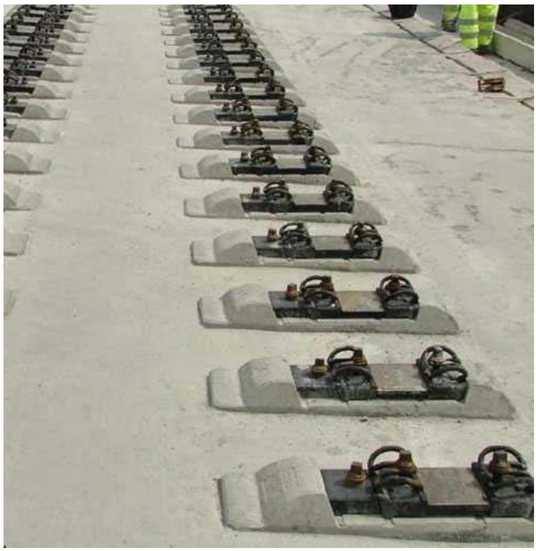
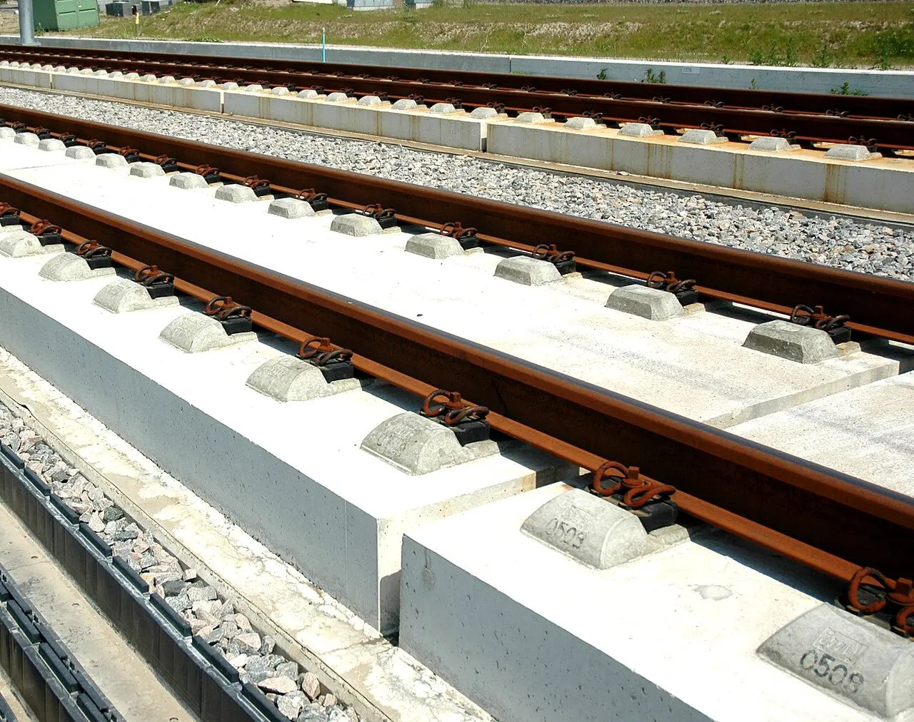
II.6 Elastomer Coated Blocks
II.6.1. VIESA
The VIESA system represents a solution based on precast blocks that allow flexibility in design and construction. This system is characterized by using concrete blocks with integrated elastic cups, facilitating rail installation with the required elasticity characteristics.
BLOCKS (VIESA).
II.6.2. SATEBA
Sateba is a leading European manufacturer (now part of the Vossloh Group) specialized in precast concrete solutions for slab track (or ballastless track).
Sateba offers several systems designed for different railway environments:
II.6.2.1. PREFARAILS® (Embedded Rail)
It is Sateba’s flagship solution for urban trams and light rail.
- Design: Rails are wrapped in a continuous rubber jacket (made from recycled tires) and inserted directly into concrete slabs.
- Benefits: Provides extreme noise and vibration damping (up to 15 dB) and electrical insulation. It is ideal for “top-down” construction, allowing for very fast installation.
II.6.2.2. High Attenuation Sleepers (M312 and S312)
These are “booted” sleepers (encapsulated) designed to be integrated into in situ poured concrete slabs.
- M312 (Monoblock): A single-piece prestressed sleeper. Offers very high vibration mitigation (> 20 dB) and is an economical alternative to “Floating Slabs” (FST).
- S312 (Bi-block): Formed by two concrete blocks joined by a steel bar, designed to reduce noise by up to 15 dB.
II.6.2.3. TW120 Integrated Sleeper
A flat-bottomed, shallow bi-block sleeper, designed specifically for embedded urban tracks.
- Application: Its compact design is ideal for zones with many underground utilities or where the track must be finished with grass, asphalt, or pavers.
II.6.2.4. Ladder Track
Sateba manufactures precast concrete “ladders” (longitudinal beams connected by transoms).
- Efficiency: It is a very robust system frequently used in “green tracks” (with grass), as it facilitates irrigation and reduces the necessary concrete depth.
II.6.2.5. Key Advantages
| Feature | Benefit |
|---|---|
| Durability | Service life superior to 60 years (compared to 15-20 for ballasted track). |
| Maintenance | Almost zero maintenance requirement; requires no tamping or ballast cleaning. |
| Precision | Maintains track geometry accurately, even at high speeds. |
| Sustainability | “EcoTrack” initiative using low-carbon cement and recycled materials. |
II.6.2.6. Project References
- Elizabeth Line (Crossrail), United Kingdom: Use of M312 sleepers for vibration control in deep tunnels.
- Chamartín-Atocha Tunnel, Spain: Implementation of embedded rail systems for high speed.
- Grand Paris Express, France: Installation of thousands of monoblock sleepers for new metro lines.
II.6.3. TRANOSA
The TRANOSA system represents another approach of precast blocks for slab track, based on modular components that integrate elastic elements. The blocks of this system are designed with elastic cups that provide the damping conditions required for correct track performance.
BLOCKS (TRANOSA).
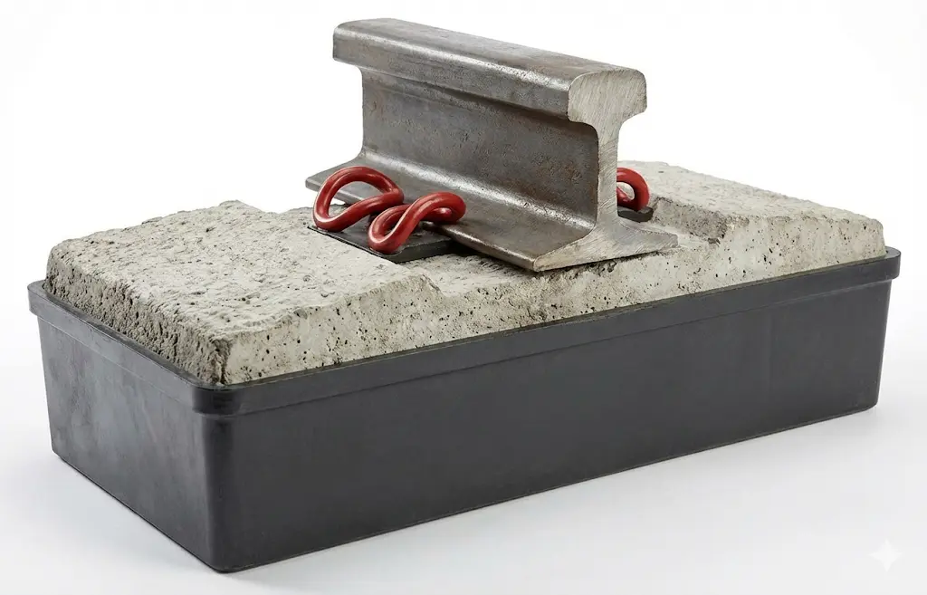
Block with elastic cup
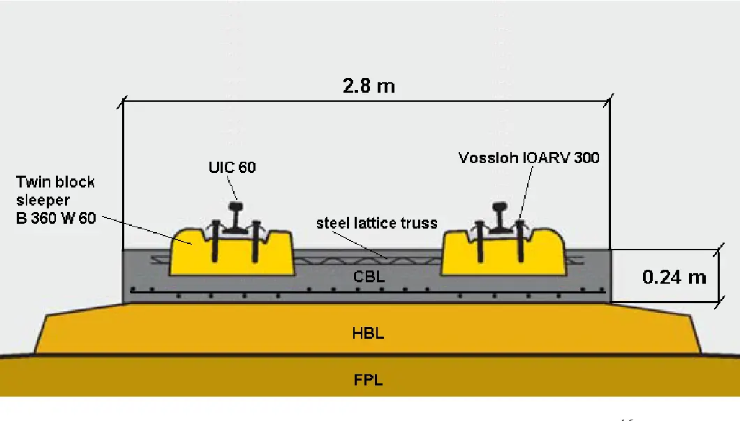
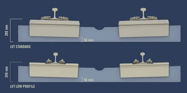
II.6.3. Low Vibration Track System LVT (Gotthard)
The Low Vibration Track (LVT) system used in the Gotthard Base Tunnel is a world-renowned example of high-performance slab track technology. Originally developed by Roger Sonneville (now part of the Vigier Rail / Sateba group), it was chosen for the Gotthard tunnel specifically because it can handle the extreme pressures and high speeds (\(250\text{ km/h}\)) of the world’s longest railway tunnel.
The LVT system is a dual-block (or bi-block) non-ballasted track. Unlike a traditional sleeper that is embedded directly into a concrete slab, the LVT system uses a “booted” method to decouple the track from the tunnel structure.
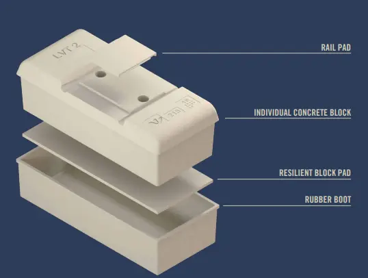
II.6.3.1. The System Components
The system consists of four primary layers that work together to dampen energy:
- Concrete Block: Two separate reinforced concrete blocks support each rail.
- Rail Pad: Sits between the rail and the block to provide primary elasticity.
- Resilient Block Pad: A flexible pad placed underneath the concrete block.
- Rubber Boot: A rubber “cup” that encloses the block and the block pad, separating them entirely from the surrounding poured concrete (the track bed).
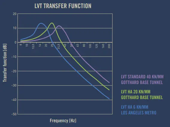
II.6.3.2. Characteristics
The Gotthard tunnel presents a hostile environment for track: high temperatures, high humidity, and massive aerodynamic pressure from passing trains.
- Dual-Level Elasticity: LVT provides two levels of damping. The rail pad handles high-frequency vibrations, while the block pad underneath the sleeper handles lower-frequency vibrations. This dual-layer approach is why it is called “Low Vibration Track.”
- High Geometric Precision: In a \(57\text{ km}\) tunnel, maintenance is incredibly difficult and expensive. Because the LVT blocks are cast into the concrete slab, the track geometry (gauge and alignment) remains fixed for decades without the need for the constant “tamping” (re-aligning) that ballasted tracks require.
- Ease of Replacement: A unique feature of LVT is that it is modular. If a concrete block or a rubber component is damaged, it can be removed from its “boot” and replaced without having to demolish the entire concrete floor of the tunnel.
- Aerodynamics and Drainage: The flat surface of the LVT slab track reduces air resistance compared to uneven ballast, which is crucial for \(250\text{ km/h}\) speeds. Additionally, the system allows for integrated drainage channels to manage the significant water ingress common in deep Alpine tunnels.
| Feature | Traditional Ballast | LVT (Gotthard) |
|---|---|---|
| Maintenance Frequency | High (every 2-5 years) | Very Low (30+ years) |
| Vibration Damping | Moderate | Very High |
| Construction Height | High (\(70\text{ cm}+\)) | Low (\(40\text{-}50\text{ cm}\)) |
| Installation Cost | Lower | Higher |
Fun Fact: There are over 380,000 LVT blocks installed throughout the Gotthard Base Tunnel, covering both tubes and the cross-passages.
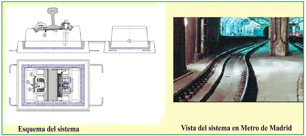
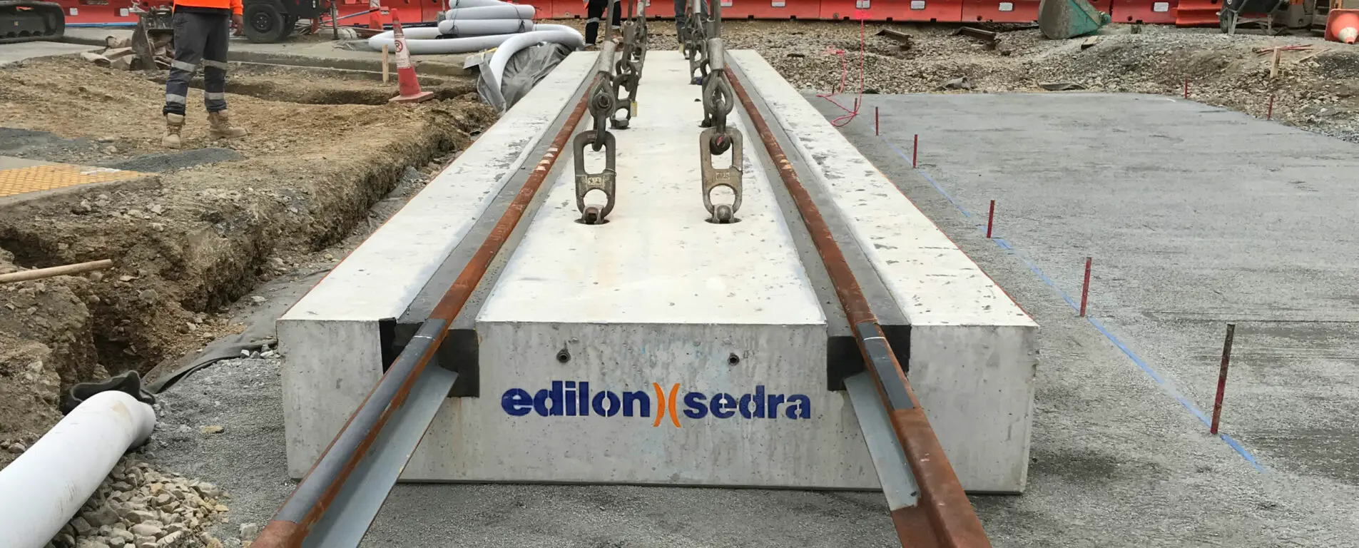
II.6.4. Edilon
The Edilon Sedra Embedded Rail System (ERS) is a ballastless track solution where the rail is continuously supported and “floating” within a channel, rather than being fixed to sleepers (ties) with traditional clips.
Instead of the point-loading you see on traditional tracks (where the weight hits specific sleepers), the ERS distributes the load evenly along the entire length of the rail.
- The Channel: A concrete slab or steel bridge deck features a longitudinal groove (the “channal”).
- The Rail: The rail is positioned precisely within this channel.
- Corkelast®: This is the “secret sauce.” It’s a two-component polyurethane resin mixed with cork. It is poured into the gaps around the rail, where it cures to provide elastic support and electrical insulation.
II.6.4.1. Key Advantages
The ERS is often the “go-to” for urban environments and heavy-duty infrastructure because it solves several engineering headaches simultaneously:
- Noise and Vibration Damping: Because the rail is wrapped in an elastic material, it absorbs the “screech” and “hum” of passing trains, making it ideal for residential areas or tunnels.
- Low Maintenance: There are no bolts, clips, or pads to tighten or replace. Once it’s poured, it’s largely a “set it and forget it” system.
- Water Tightness: The system is completely sealed, preventing water from seeping into the concrete structure, which is vital for bridges and tunnels to prevent corrosion.
- Stray Current Protection: The resin acts as an insulator, preventing electricity from the rails (in electric train systems) from leaking into the ground and damaging nearby pipes or cables.
II.6.4.2. Common Use Cases
- Street Trams & Light Rail: Allows vehicles and pedestrians to cross the tracks easily because the rail is flush with the road surface.
- Bridges and Viaducts: Reduces the dead weight on the structure by eliminating the need for heavy ballast (rocks).
- High-Speed Rail: Provides a high level of stability and precision required for 300+ km/h travel.
- Level Crossings: Durable enough to handle heavy truck traffic crossing over the rails.
II.6.4.3. Installation Process
- Preparation: The concrete channel is cleaned and primed.
- Alignment: The rail is suspended in the channel using specialized jigs to ensure perfect vertical and horizontal alignment.
- Pouring: The Corkelast® compound is mixed and poured into the voids.
- Curing: Once the resin hardens, the jigs are removed, and the track is ready for service.
II.7. Direct Sleeper Support
II.7.1ATD
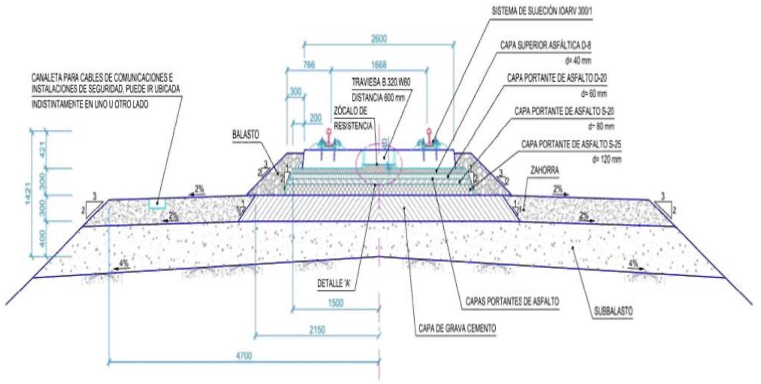
The ATD system (AsphalTragschicht mit Direktauflagerung) constitutes an alternative solution that uses asphalt layers as the base element of the superstructure. The construction composition begins with a 40-centimeter sub-ballast layer over which a uniform 30-centimeter layer of cemented granular material (gravel-cement) is extended. Subsequently, four layers of asphalt are placed, the top layer being improved with polymer addition to increase its durability and elasticity properties. Once the asphalt layers have reached their thermal and structural stability, the sleepers are positioned on the asphalt. Sleeper fixation is achieved by injecting a synthetic putty through holes specifically drilled in the upper part of each sleeper.
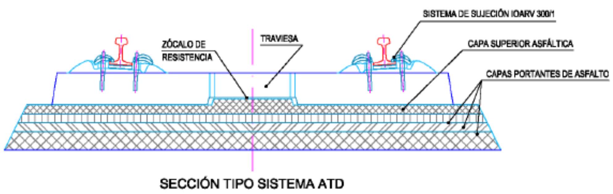
ATD SYSTEM TYPE SECTION
II.7.2. Getrac
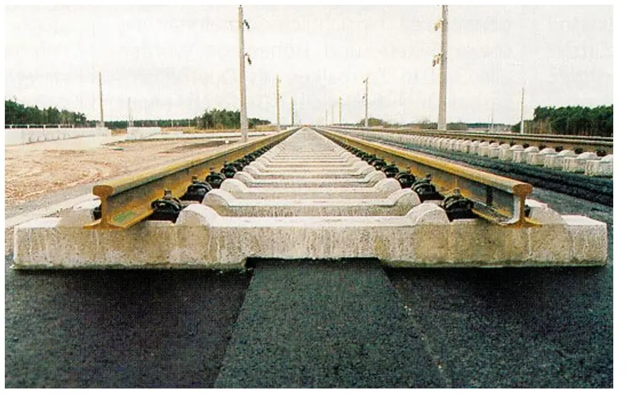
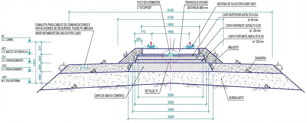
The Getrac system is based on a layered architecture where the support slab consists of high-quality asphalt concrete, upon which a monoblock concrete sleeper is positioned. The total asphalt concrete package rests on a base of cemented granular material (gravel-cement), reaching an approximate thickness of 30 centimeters for the support structure.
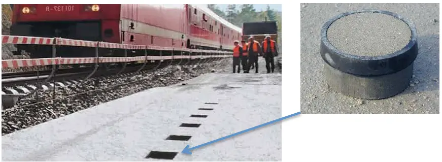
The multi-layer structure allows for efficient load distribution. The first asphalt layer acts as a bonding element with the subgrade and distributes loads to the lower layers. The second layer fulfills the function of an elastic element, allowing damping of stresses generated in the upper layer where sleepers are placed. The union between sleeper and asphalt support layer is made by specially shaped concrete pieces, called “stoppers”, which create connection points between both elements.
- The first layer serves as a union with the subgrade and distributes loads to it; the second layer is a spring allowing damping of tensions produced in the upper layer, the support layer where sleepers are placed.
- The union between the sleeper and the support layer is made through a concrete piece in the form of a block, called “stopper”.
GETRAC SYSTEM TYPE SECTION
II.13. Performance
When selecting the most suitable slab track system for a given application, it is fundamental to understand the performance characteristics that each typology offers. Layered or monolithic constructions effectively reduce stresses derived from loads transmitted through the structure, facilitating repair operations when needed. However, they have the limitation of having a single plane of elasticity, which can cause acoustic problems.
Block systems provide considerable noise reductions at low frequencies and offer considerable vibration damping. However, in open-air applications, they can present durability problems related to water retention in the cups, as well as damage from repeated freeze-thaw cycles.
Embedded rail systems achieve an effective reduction of stresses by minimizing rail fatigue, which remains completely protected from atmospheric agents. These systems allow vehicle transit over their surface and distribute loads homogeneously. Their main disadvantage lies in the complexity of repair operations.
Floating slabs offer the greatest reduction of noise and vibrations by having multiple planes of elasticity. The use of precast elements allows for efficient systematization of the construction process, although it requires very strict control of component positioning. Their initial cost is considerably higher than other solutions.
Chapter III Slab Track Assembly
- Introduction
- Systems
- Slab track assembly
- Construction procedures
- Slab track in Spain
- Comparison with ballasted track
The construction process of slab track differs significantly from that of conventional ballasted systems. The monolithic nature and structural rigidity of these systems impose very demanding requirements in the preparation, execution, and control phases. This section examines the specific technical considerations that must be taken into account in different topographical and structural contexts.
III.1. Slab Track on Subgrades
The implementation of slab track on natural terrain demands support conditions substantially superior to those required for conventional track on ballast. This fundamental requirement stems from the inherent stiffness of the system, which makes it vulnerable to undermining or flexural failure if the support does not provide uniform contact.
It is necessary to carefully avoid a series of geotechnical problems that can compromise the system’s integrity. These include significant deformations or deflections, as well as continuous or irregular settlements of the subgrade. Leaching or washing out of foundation materials must also be prevented, as well as the possibility of local collapses. Equally important is the control of soil behavior under moisture variations, freeze-thaw cycles, and thermal expansion or contraction processes.
The primary objective in the design of the support terrain is to minimize, as much as possible, the natural residual settlements of the subgrade prior to track installation, as well as those that may occur during subsequent operation. Given this critical requirement, when significant geotechnical risks exist, the most prudent solution is usually the adoption of conventional ballasted track, which provides greater flexibility to accommodate terrain irregularities.
III.2. Slab Track on Embankments
The installation of slab track on artificial fills requires the implementation of a series of preventive and construction measures to guarantee the long-term stability of the system. These measures must be coordinated during the design, construction, and control phases.
Firstly, it is fundamental to limit the height of the embankment, recognizing that while there is a correlation between height and settlements, the relationship is not necessarily linear. In cases where the foundation soil presents some bearing capacity, it is advisable to carry out foundation treatment works, improving both its impermeability and the stability of the underlying ground. In soils with low or no bearing capacity, or those presenting significant deformability (as in documented cases in Holland and Japan), it is necessary to execute special works for support or foundation improvement.
Optimizing the materials used in the construction of embankments and their seating layers contributes significantly to system stability. Whenever possible, higher quality materials than conventional ones should be selected. In parallel, special attention must be paid to compaction processes during construction, ensuring that specified compaction levels are achieved and verified through field tests.
| Material Type | Compaction | Vertical Stiffness |
|---|---|---|
| SUB-BALLAST | N/A | \(\mathrm{E}_{\mathrm{v} 2}>1.200 \mathrm{~kg} / \mathrm{cm}^{2}\) |
| FORM LAYER (Material QS3) | \(\mathbf{1 0 0} \boldsymbol{\%}\) Modified Proctor | \(\mathrm{E}_{\mathrm{v} 2} \boldsymbol{>} \mathbf{8 0 0 ~ k g} / \mathbf{c m}^{2}\) |
| SOIL QUALITY QS3/QS2 (Embankment) | \(\mathbf{9 5} \boldsymbol{\%}\) Modified Proctor | \(\mathbf{E}_{\mathrm{v} 2} \boldsymbol{>} \mathbf{6 0 0 ~ k g} / \mathbf{c m}^{2}\) |
III.3. Slab Track in Cuts
The construction of slab track on excavations in natural terrain (cuts) presents different challenges than those found in embankments, although equally demanding from a geotechnical point of view. The risk mitigation strategy comprises two main measures.
Firstly, when the excavated soil presents some bearing capacity, one must proceed to sanitize the foundation, particularly improving its impermeability and increasing the general stability of the ground. This improvement is especially critical in cuts, where water infiltration effects and mass movements can be more pronounced than in embankments.
Secondly, when soils present low or no bearing capacity, or when they demonstrate significant deformability, it is essential to design and implement special works for foundation improvement or structural support. Experiences from Holland and Japan provide well-documented examples of sophisticated solutions in these circumstances.
Complementary to the above, the use of highest available quality support materials is strongly recommended, selecting soils of category QS3, QS2 or QS1 when necessary. Rigorous compliance with stiffness and compaction specifications for each layer, together with an intensified in-situ quality control program, are essential elements for the success of this type of project.
| Material Type | Compaction | Vertical Stiffness |
| :— | :— | :— |
| SUB-BALLAST | N/A | \(\mathrm{E}_{\mathrm{v} 2}>1.200 \mathrm{~kg} / \mathrm{cm}^{2}\) |
| FORM LAYER (Material QS3) | 100\% Modified Proctor | \(\mathrm{E}_{\mathrm{v} 2}>800 \mathrm{~kg} / \mathrm{cm}^{2}\) |
| SOIL QUALITY QS3/QS2 (Cut) /QS1 (Cut) | 95\% Modified Proctor | \(\mathrm{E}_{\mathrm{v} 2}>600 \mathrm{~kg} / \mathrm{cm}^{2}\) |
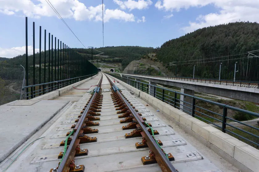
III.4. Slab Track on Viaducts
The incorporation of conventional ballasted track on viaduct structures introduces a series of problems that can be significantly mitigated by adopting slab track systems.
In viaducts with ballasted track, the rigid contact between the ballast and the concrete surfaces of the deck slab generates stress concentrations that are exacerbated by the inherent confinement of the material. Additionally, habitual maintenance operations (leveling and alignment by ballast tamping) can accelerate material deterioration under these conditions of increased stiffness.
When operation demands very high levels of service, it may be necessary to arrange elastomeric elements under the sleepers or on the slab surface to reduce contact stiffness and decrease interface hardness, thus minimizing ballast wear and reducing stresses. In special circumstances, fastening systems with more elastic characteristics than conventional ones can be installed.
Alternatively, it is possible to specifically design the viaduct structure to house a particular slab track system, considering in the design the permanent load increase that these systems generate. Simultaneously, it is feasible to decrease the admissible dynamic amplification factors of the structure due to the superior continuous track geometry quality provided by these systems.
However, the integration of slab track with viaduct structures requires ensuring compatibility of multiple aspects: relative vertical movements between the deck and the track bearing slab must be accommodated through rotational freedoms and controlled relative movement systems. Longitudinal deck movements due to thermal effects must be compatibilized with those of the rail. Transverse movements of the deck with respect to abutments, or between independent decks, must be conveniently limited. Finally, the transmission of transverse and longitudinal forces from the track to the structure must guarantee a safe flow of forces.
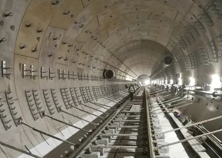
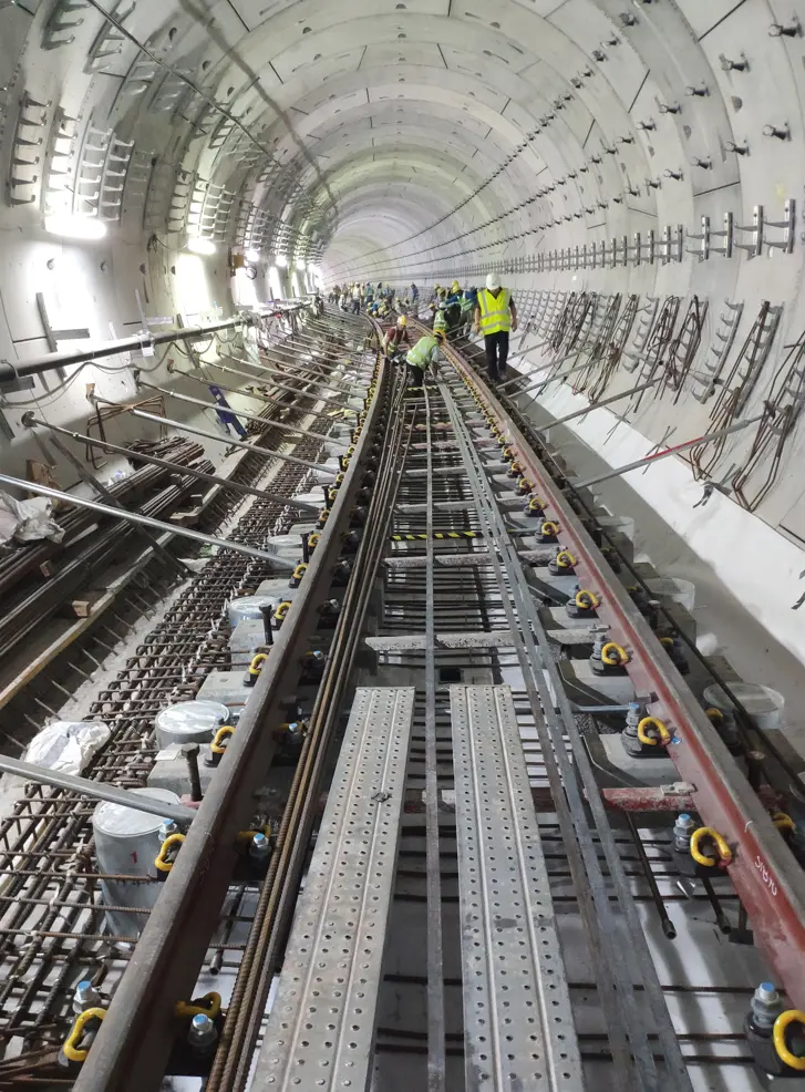
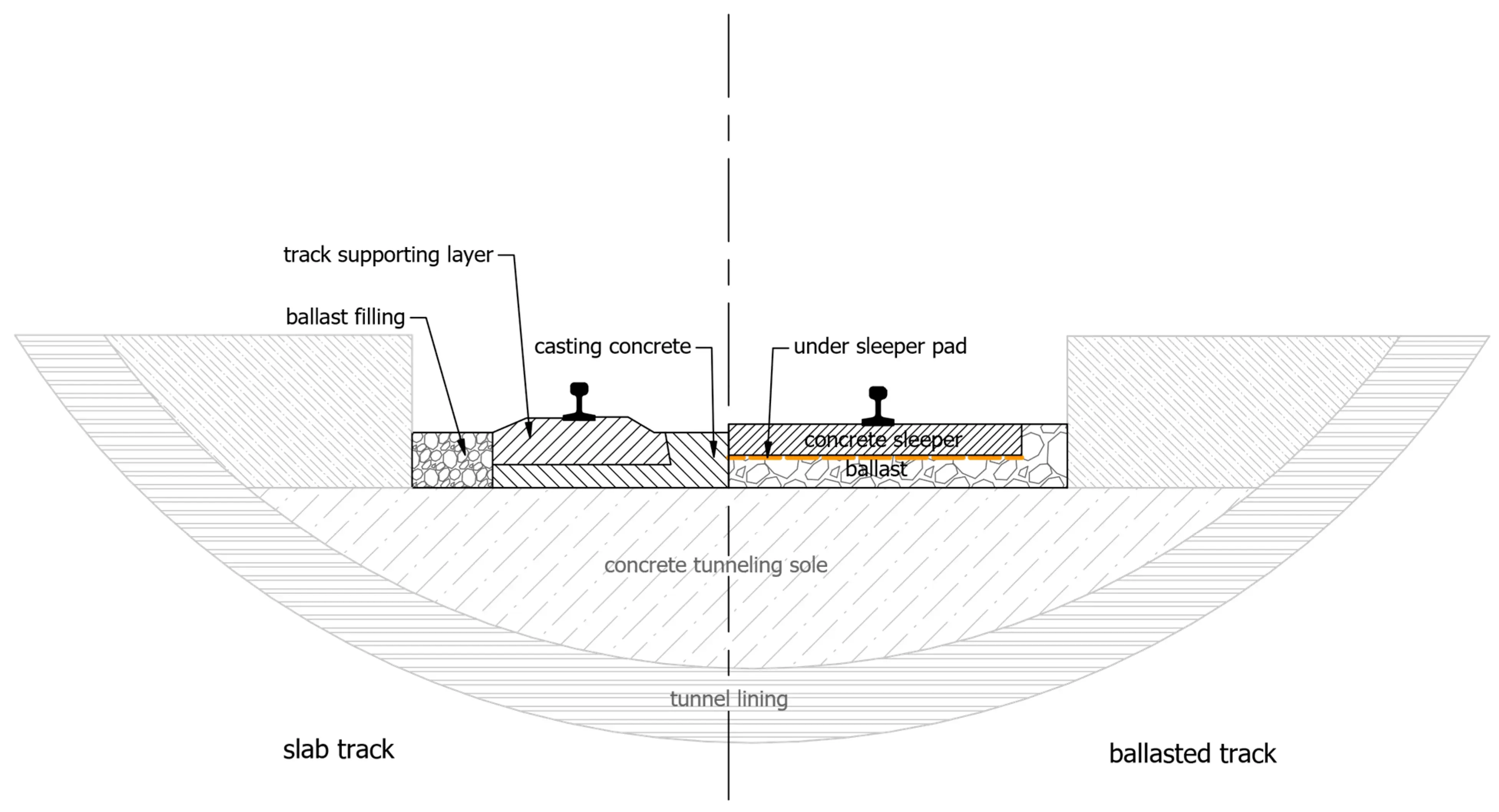
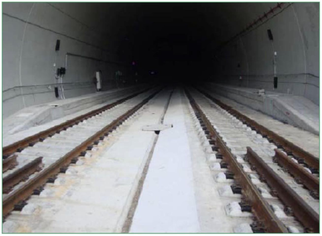
III.5. Slab Track in Tunnels
Railway tunnels constitute the most favorable context for the implementation of slab track systems, by virtue of the multiple advantages these systems bring to this type of infrastructure.
Conventional ballasted track in tunnel contexts presents a series of significant limitations. The required construction height is considerably greater than that of slab track systems, implying excavations of larger section and, consequently, higher costs and construction complexities. Routine maintenance operations for ballasted track (tamping and cleaning) present exceptional difficulties in the confined context of a tunnel. Track stability and availability are compromised by the tendency of ballast to shift under repeated dynamic loads in the closed tunnel environment. Access to the tunnel for maintenance or emergency operations is inherently complicated, and evacuation of passengers on foot in case of an incident, as well as access for emergency vehicles, present significant restrictions. Finally, operational experience has documented the occurrence of settlements due to ballast instability, as well as problems of contamination of support layers and water accumulation, derived from the clogging of track drainage systems.
Conversely, tunnels constitute the most compatible infrastructure for slab track assembly. The design of the tunnel invert or deck slab can be executed specifically considering the stresses and characteristics of a particular slab track system, taking into account the permanent weight increase these systems generate. In many cases, the concrete bearing slab can be considered as structurally collaborating in the tunnel’s resistance, particularly when transverse stitching reinforcement has been arranged between the slab and the resistant structure of the invert.
Thermal stability inside the tunnel usually implies that there are no significant transverse or longitudinal movements of the structure, thus eliminating the need to compatibilize complex movements between different components. Finally, it is essential to design and implement an adequate waterproofing and drainage system specifically dimensioned for the characteristics of slab track in a tunnel context.
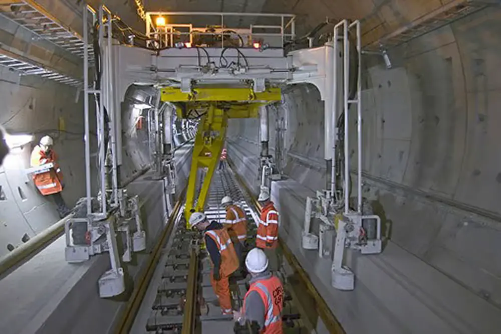
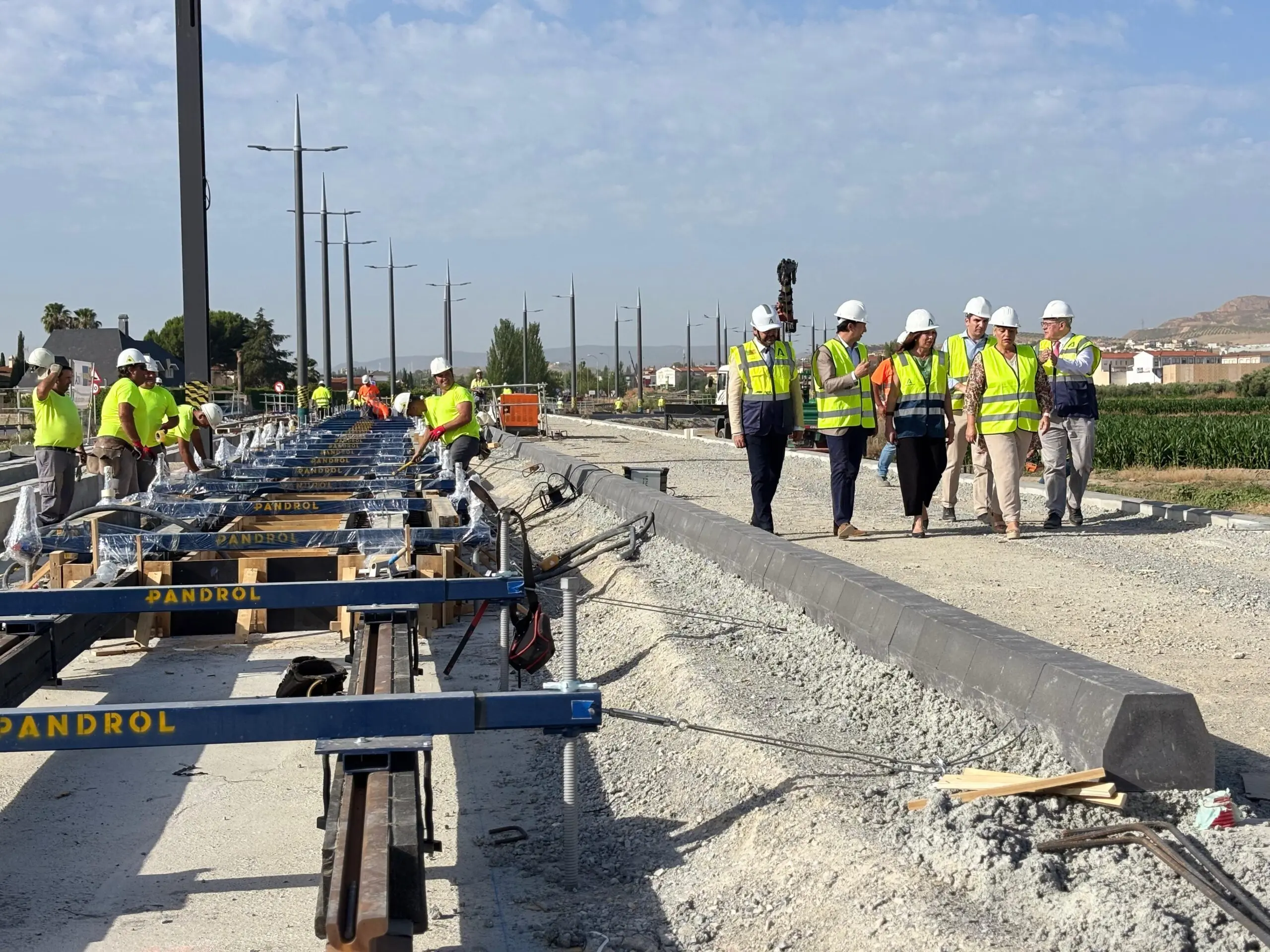
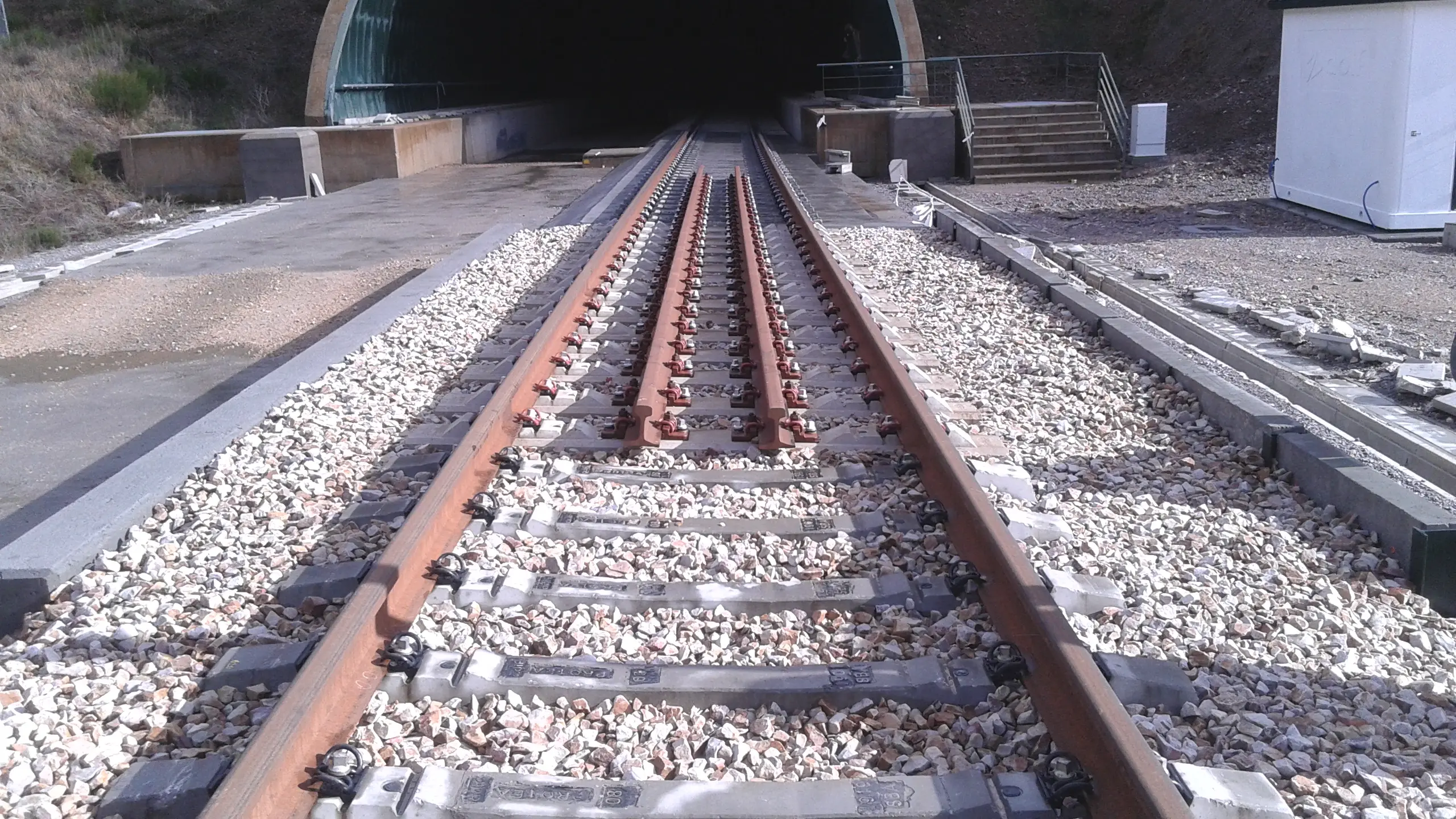
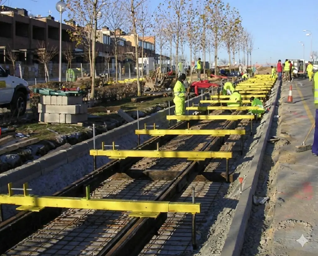
Chapter IV Construction Procedures
The execution of slab tracks requires highly systematized and controlled construction procedures. This chapter examines in detail the typical operations involved in the installation of a RHEDA 2000 system, which constitutes one of the most widely used systems in Spanish and European projects. The procedures described here illustrate the general principles applicable to other systems, although with specific adaptations according to their particular characteristics.
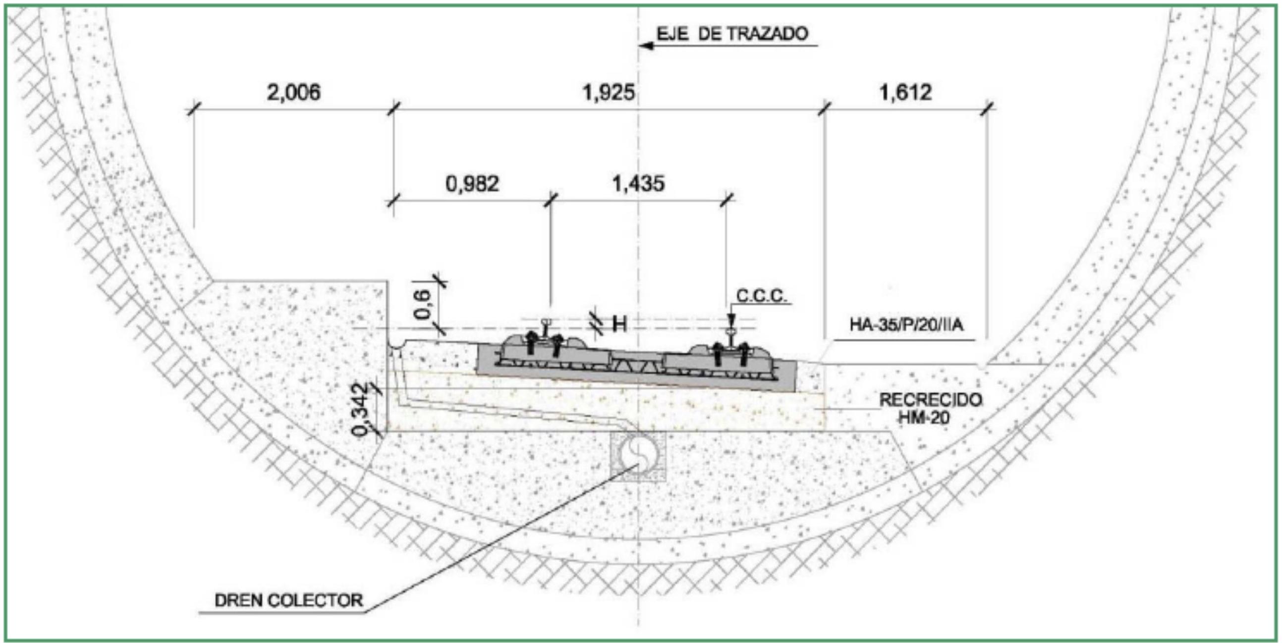
Type sections (1).
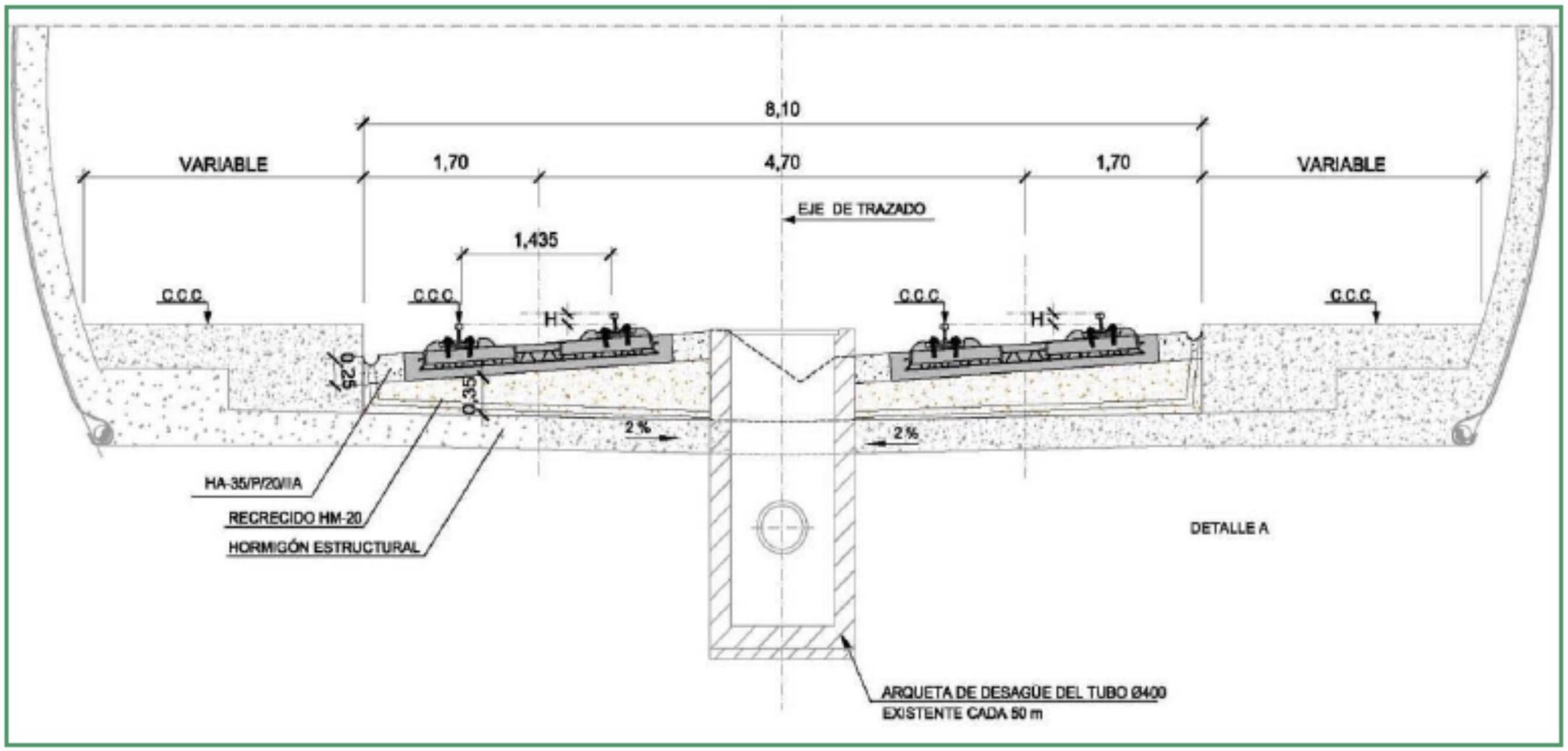
Type sections (2).
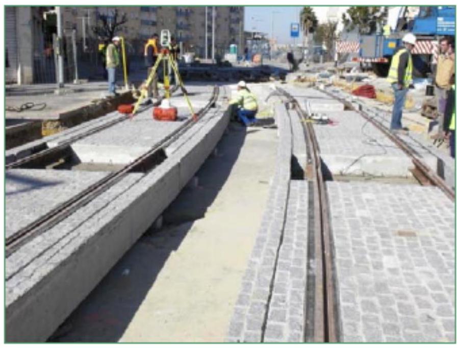
Surveying - Staking Out Bases
IV.2. Marking Points and Surveying of the Invert
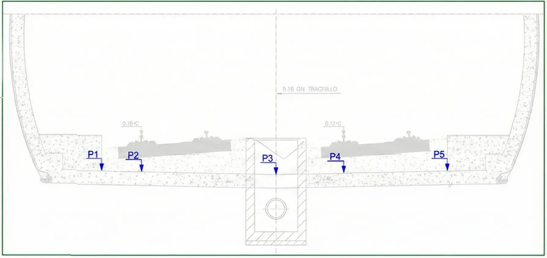
The initial staking out operations constitute the foundation upon which the precision of the entire subsequent installation rests. The topographic survey of the existing invert is carried out through systematic sampling, taking 5 measurement points per cross-section, spaced longitudinally at intervals of 10 meters.
Once the topographic information of the support is obtained, the track layout adjustment proceeds, verifying that the resulting thickness between the existing invert and the elevation of the rail central axis remains within specified tolerances (typically 0.493 millimeters). The fitting of the track layout in plan and profile requires simultaneous validation of multiple parameters: both fundamental geometric parameters (alignment, cant, longitudinal gradient) and functional parameters (curvature radii, cant transitions). Concurrently, infrastructure clearances must be verified against current safety and operational regulations.
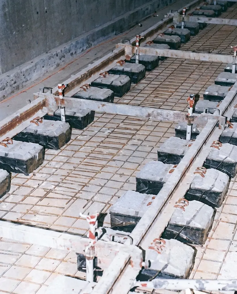
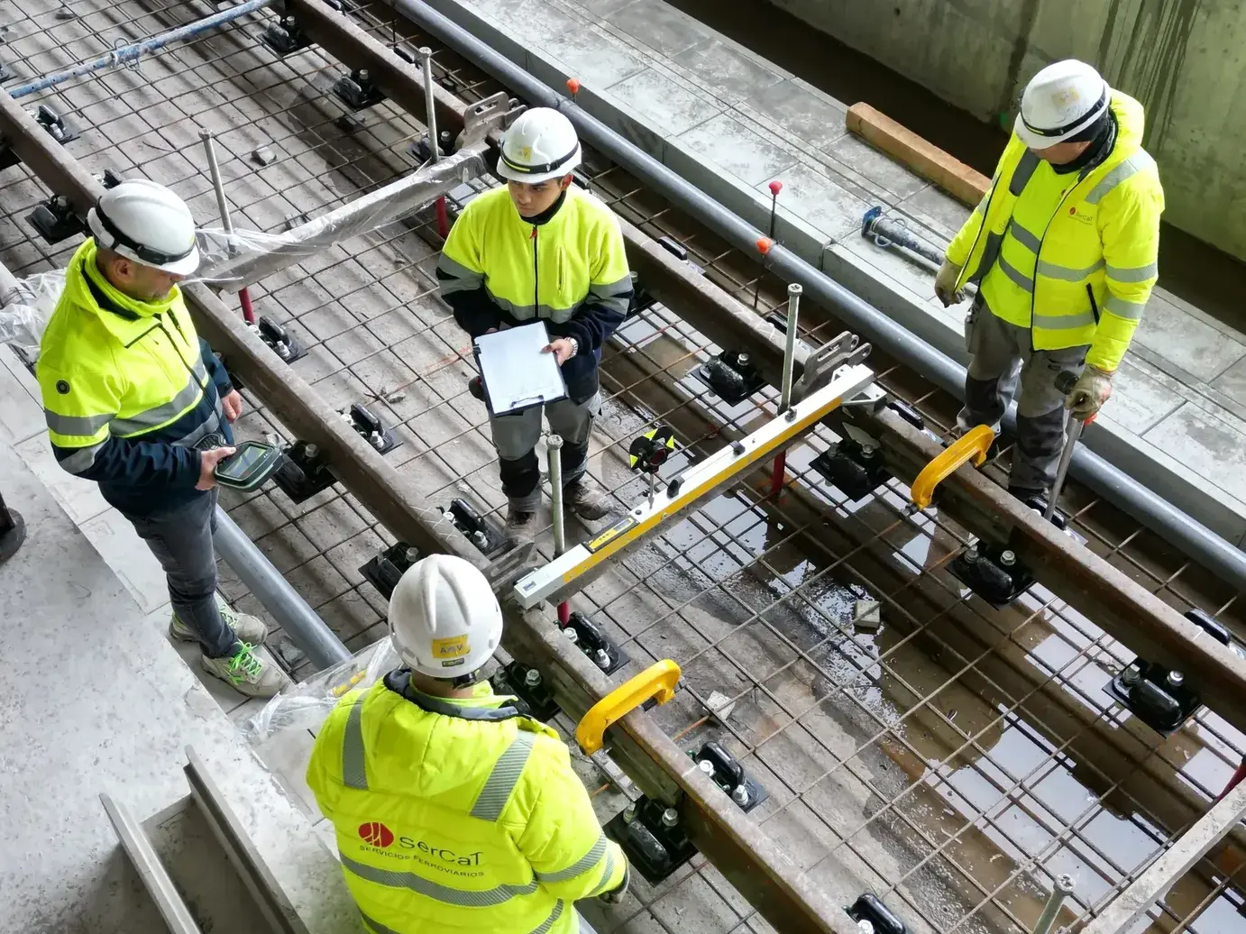
IV.3. Preparation of the Invert and Sleeper Positioning
The first construction phase comprises the execution of the mass concrete invert of class HM-20. This layer constitutes the base upon which the entire superstructure rests. In cases where it is necessary to maintain or adjust the cant of the layout, a canted invert can be designed that already provides the necessary rail inclination, facilitating subsequent assembly operations.
Once the strength of the invert concrete is reached, precise positioning of the sleepers on it proceeds, considering the previously validated geometric layout. Sleeper positioning constitutes a critical operation, as it defines the definitive position of the rail in the final structure.
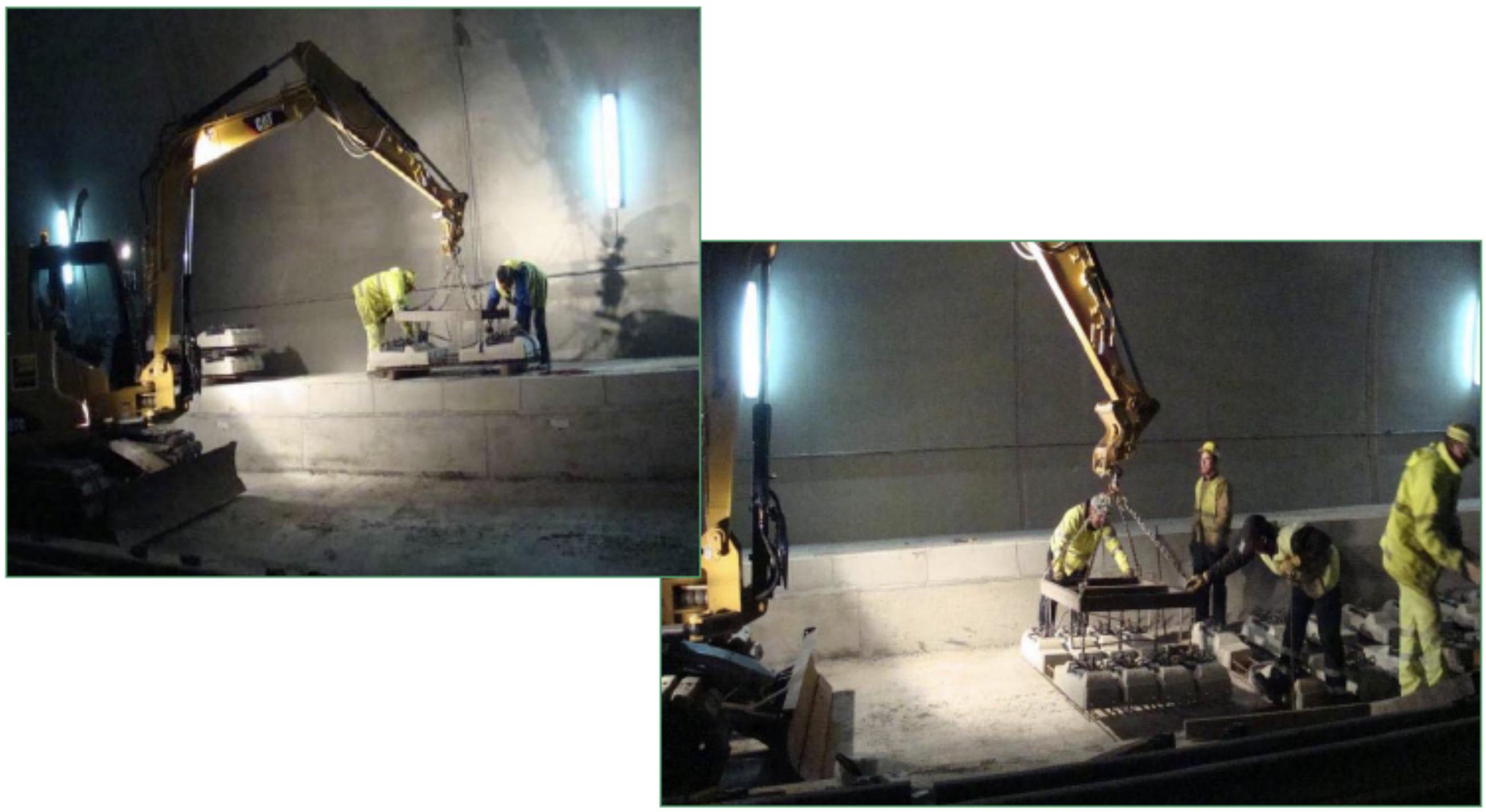
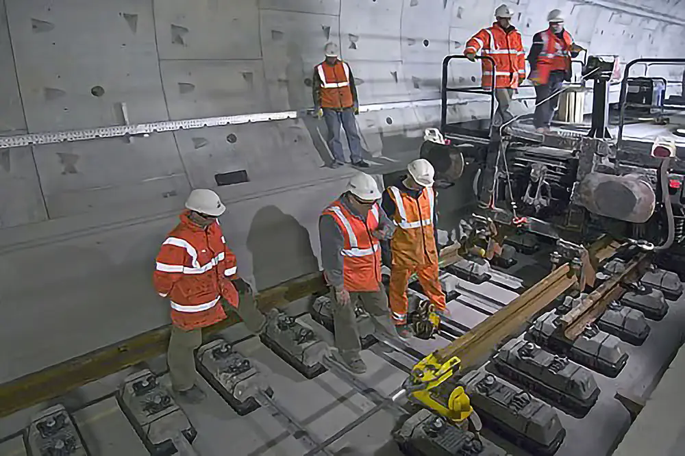
Rail unloading at the work site constitutes an operation requiring care to avoid damage. The rail is supplied in long sections or bars that are unloaded using appropriate equipment. Rail assembly on the sleepers is performed following precise procedures, with subsequent track spiking to assure initial position during subsequent leveling and adjustment operations.
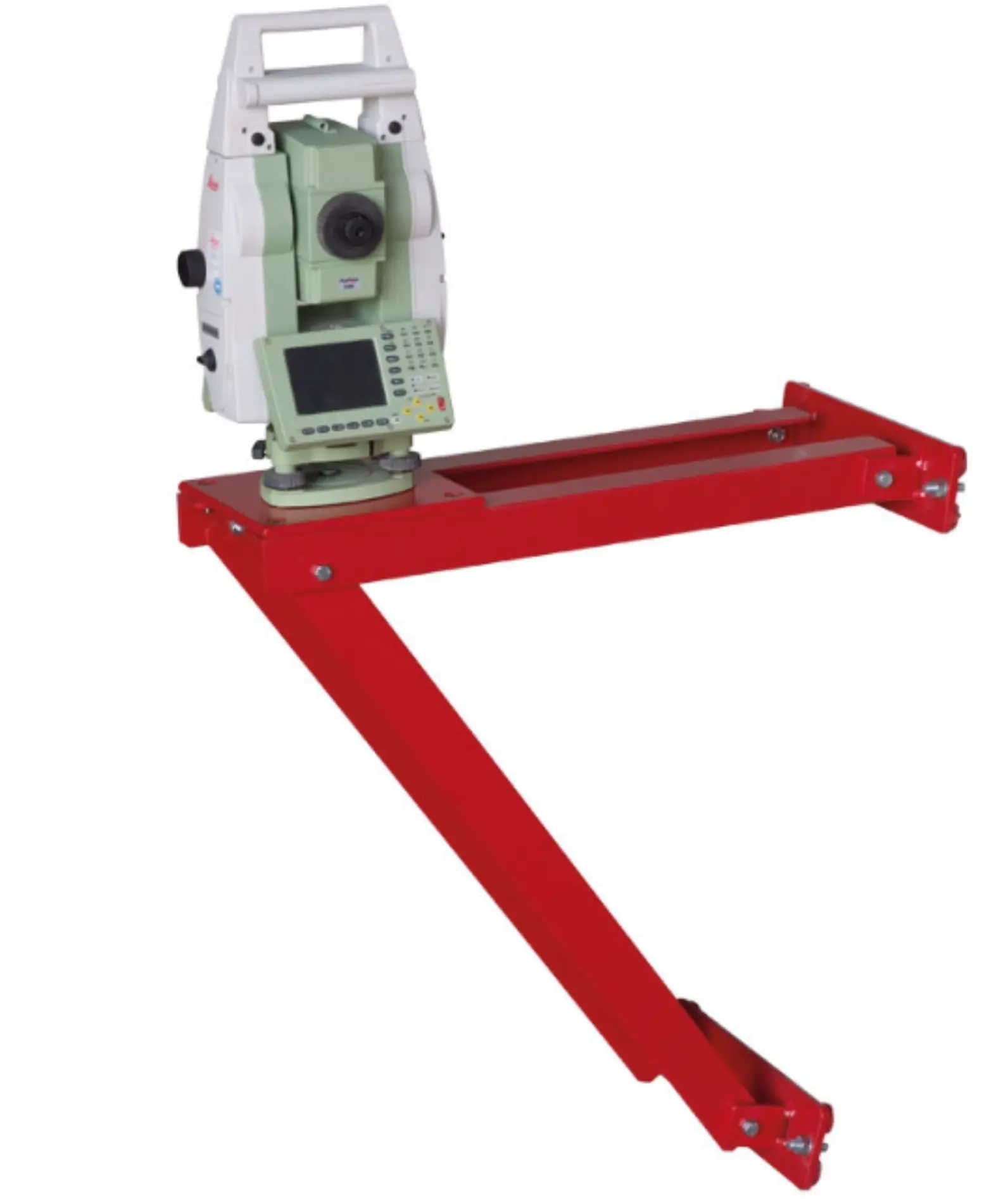
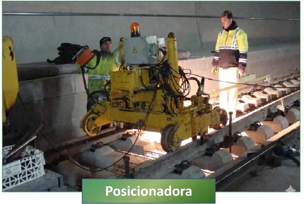
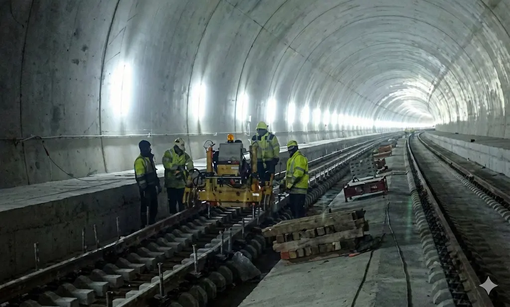
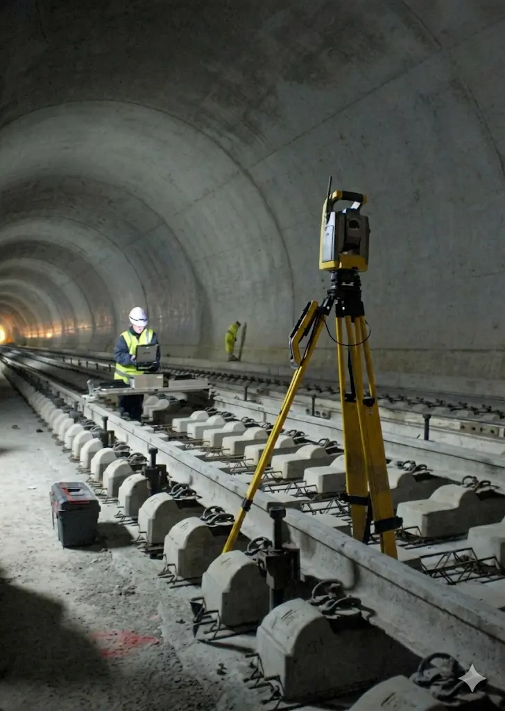
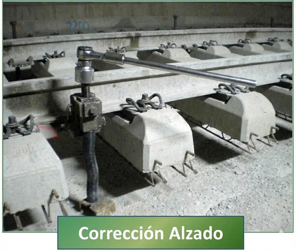
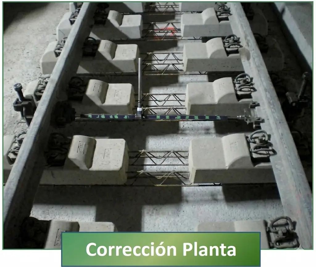
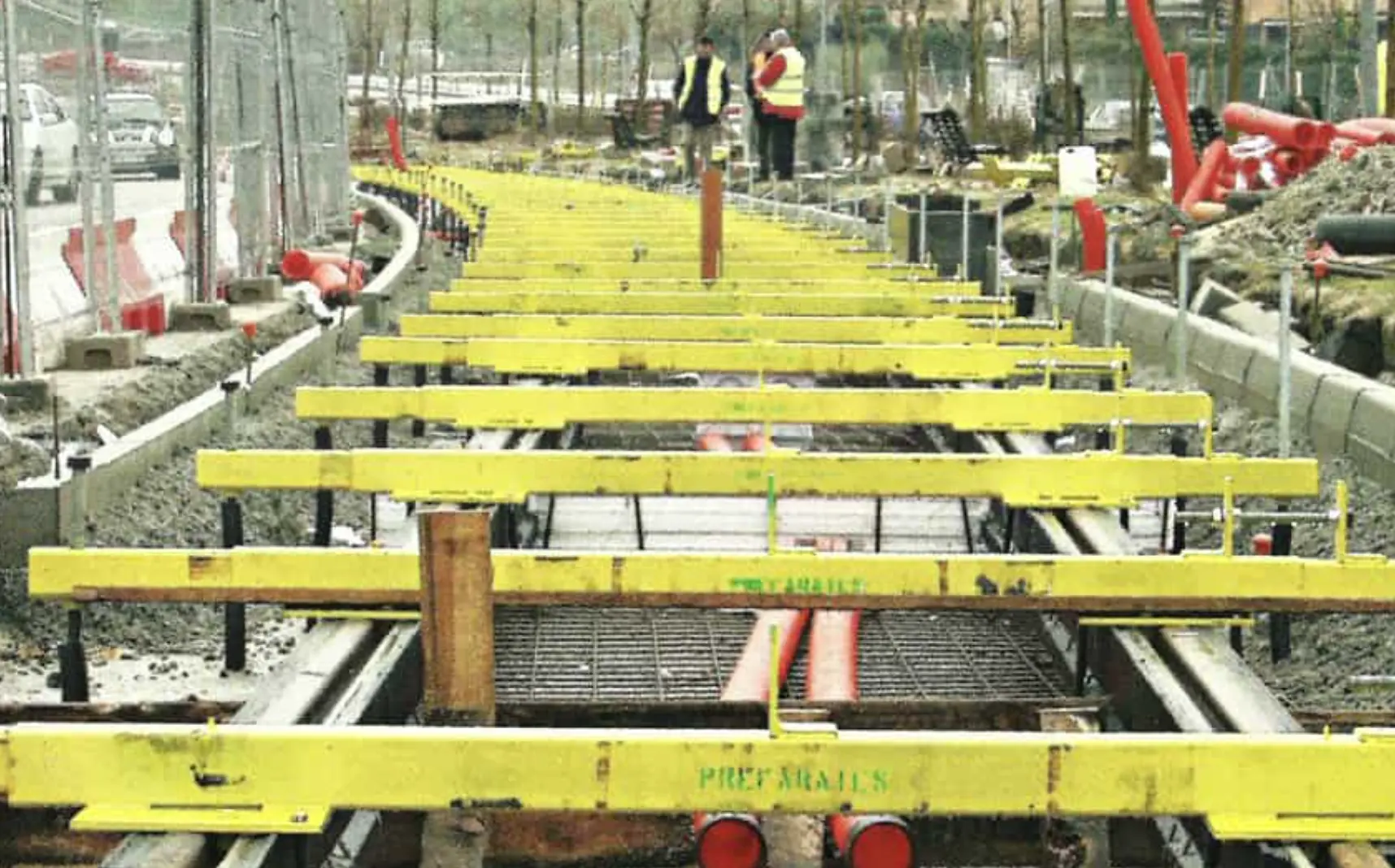
The track leveling operation constitutes a critical step in the construction sequence. Spindles (lifting screws) placed at intervals of approximately 1.80 meters are used to adjust both horizontal alignment and vertical leveling of the track. These spindles allow approximating the rail position to its specified theoretical values, considering both plan parameters (alignment) and profile parameters (leveling).
Topographic adjustment (1).
IV.4. Reinforcement and Concreting
The structural reinforcement using steel reinforcement constitutes an essential component of the monolithic concrete slab. In tunnel contexts, conventional reinforcement may be partially substituted by polypropylene fibers, which provide distributed cracking control. However, at tunnel portals, where abrupt temperature variations occur, complete traditional reinforcement is maintained.
Longitudinal reinforcement typically consists of 8 bars of 20 millimeters diameter, while transverse reinforcement comprises bars of 20 millimeters diameter with a total length of 2.70 meters. Laps between bars are designed with a minimum length of 1.20 meters, ensuring that at least 3 bars are welded. Grounding points are established every 100 meters maximum, and special connectors are installed in the last 10 sleepers for drainage purposes.
The concreting of the slab is poured in successive layers. The first layer of HM-20 is placed with specified thickness (typically 250 millimeters), incorporating polypropylene fibers in doses of 900 grams per cubic meter when this technology is used. Subsequently, a second layer of HM-35 concrete with higher performance is concreted over the first. Sleeper watering is applied and careful vibration is executed to ensure correct concrete consolidation, elimination of voids, and complete material penetration around sleepers and reinforcement.
A crucial phase subsequent to track system concreting is the formation of continuous welded rails. This process integrates multiple rail sections into continuous longitudinal units, improving dynamic behavior and reducing stress at intermediate joints. Aluminothermic welding constitutes the most widely used method for this operation, providing high strength and durability joints.
Metal struts are subsequently installed to stiffen the sleeper assembly, preventing lateral displacements during the passage of the first trains and until the concrete structure reaches its full strength. Transitions between slab track and ballasted track are carefully constructed to avoid abrupt stiffness changes that could generate excessive vibrations or dynamic impacts.
Chapter V Slab Track in Spain in the Adif Network
The adoption of slab track systems in Spain has followed a gradual trajectory, reflecting the need to validate these technologies in operational contexts prior to their massive implementation. Current availability data provide a clear perspective on the state of technology in Spanish railway infrastructure.
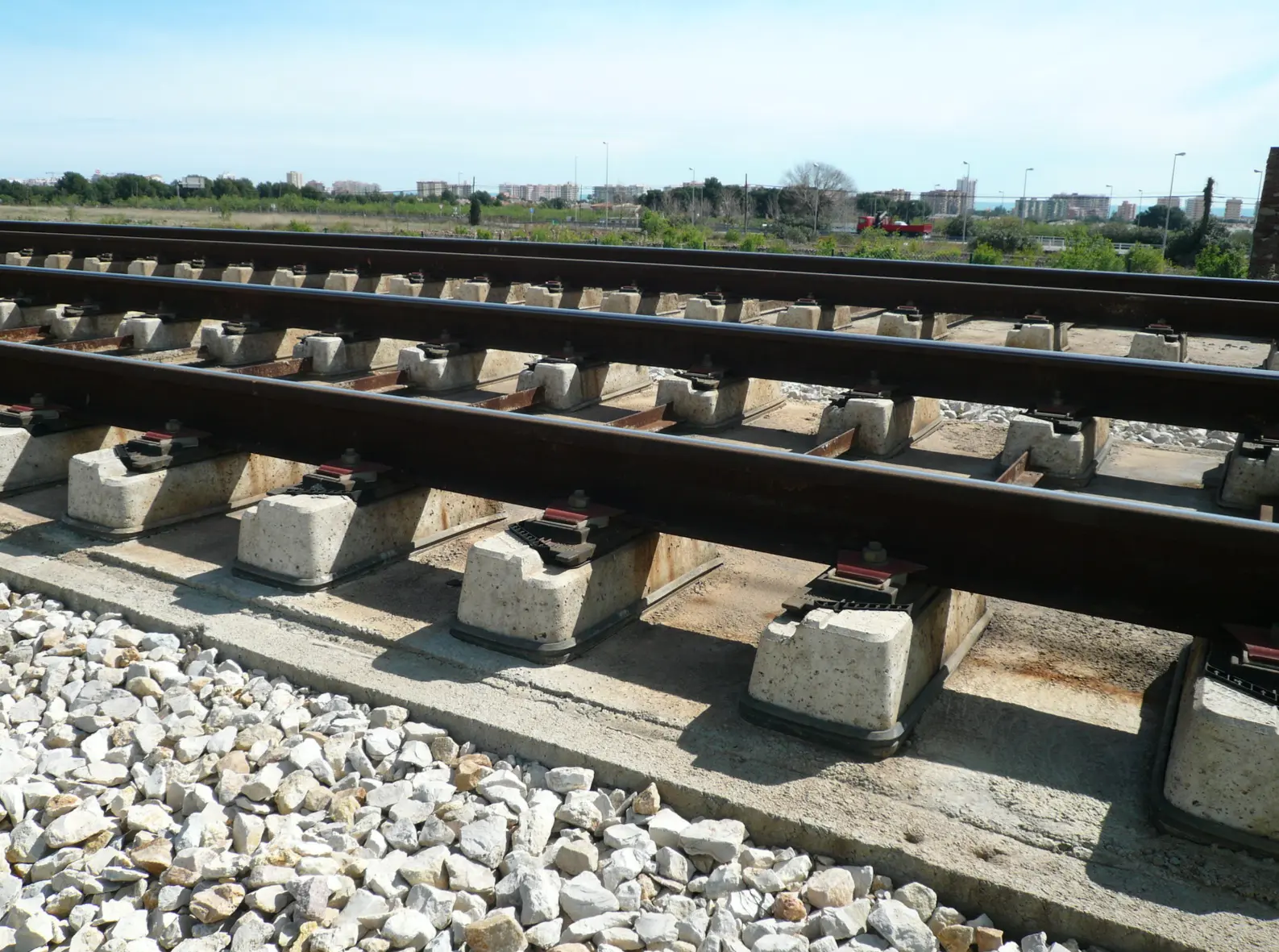
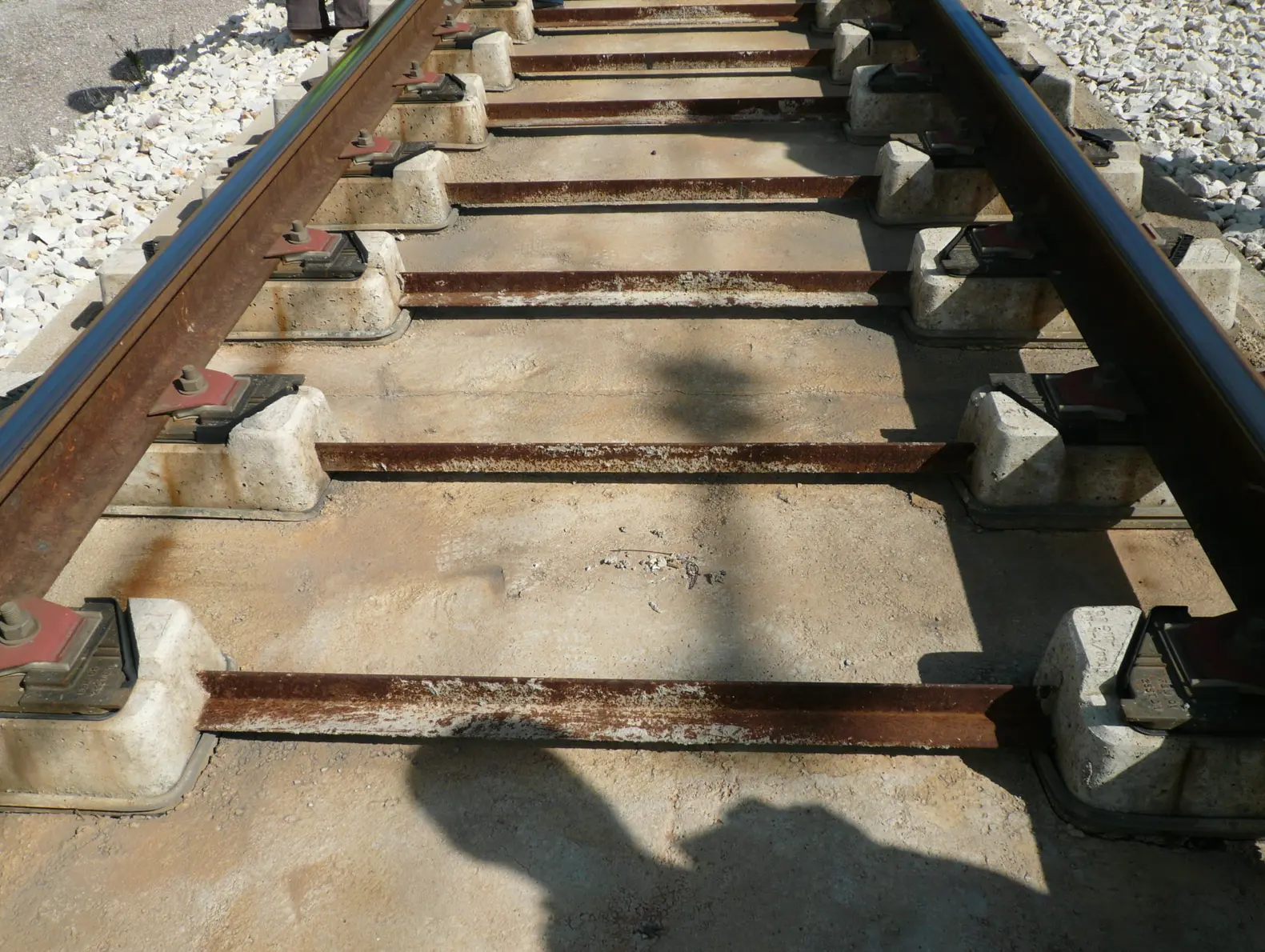
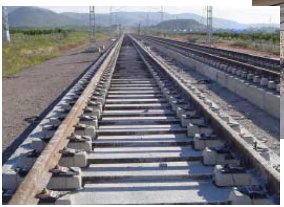
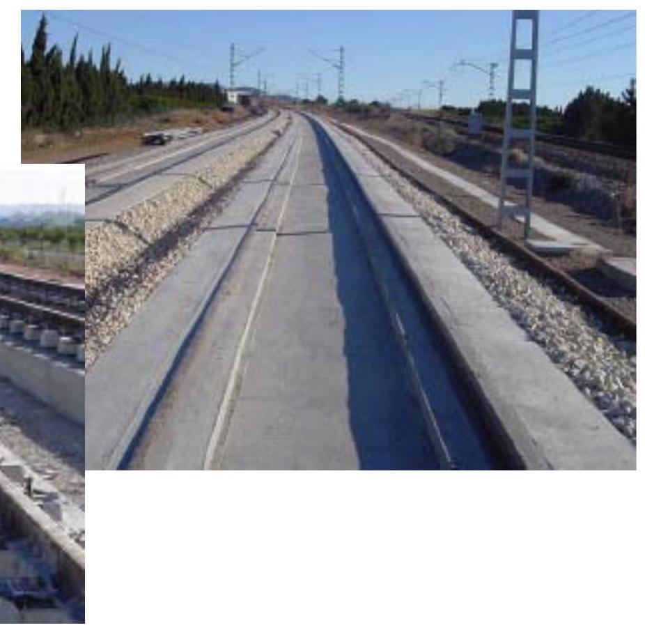
In the ADIF Conventional Network with Iberian gauge, 58 kilometers of slab track are currently in operation, a figure representing barely 0.5% of the total conventional network. These sections are located predominantly in tunnels and stations, contexts where system advantages are most pronounced. An important milestone in technology validation constitutes a 2.5-kilometer section located in the Mediterranean Corridor (Valencia-Barcelona line, Las Palmas-Oropesa segment) operating at 220 km/h. This section, installed in 2003, has served as a test bed to validate high-performance slab track models that were subsequently implemented in the High Speed Network. It is expected that with the completion of the Atlantic Axis works (Vigo-La Coruña), the total length of slab track in the Conventional Network will reach approximately 70 kilometers.
Regarding the ADIF High Speed Network with international gauge, 75 kilometers of slab track are currently registered in operation, representing approximately 3% of the total network. These kilometers are distributed in tunnels, station accesses, and station complexes. An experimental section of significant importance is located between Medina and Olmedo on the Madrid-Valladolid High Speed Line, also operating at 220 km/h. The institutionalization of the research and development effort in this matter was concretized with the creation, in the early 2000s, of the WORKING GROUP FOR THE DEVELOPMENT OF BALLASTLESS TRACK.
V.1. Application Criteria
The regulations governing the use of slab track in Spain are established in ORDER FOM/3317/2010 of December 17, which approves the Instruction on specific measures for improving efficiency in the execution of public works for railway, road, and airport infrastructures of the Ministry of Development (published in the Official State Gazette on December 23, 2010).
According to this regulation, slab track must be mandatorily installed in all tunnels with length exceeding 1,500 meters, provided there are no other special circumstances advising against its implementation. For cases where there is a succession of tunnels and viaducts that together reach that length, for tunnels between 500 and 1,500 meters in length, or when other technical considerations so justify, the decision between slab track or conventional track must be based on a complete technical-economic study, including analysis of predicted traffic type, construction conditions and costs, operation and maintenance costs, as well as the cost associated with necessary transitions between track systems.
Circular Resolution 2/2012 of the Directorate General of Railways complements the previous provisions with specific recommendations for tunnel track superstructure design. For renewal, rehabilitation, or conditioning actions in existing tunnels with very restrictive geometric conditions (reduced clearances, very small horizontal radii, maximum cants, reduced distances between axes, etc.), the viability of substituting conventional superstructure with slab track must be analyzed, opting for this system whenever it is reasonably viable from constructive, economic, and geometric points of view.
Additionally, the use of slab track is recommended in railway stations and in singular locations where the objective is to uniformize track superstructure and thus facilitate maintenance coordination along lines containing successions of long tunnels, combinations of tunnels and viaducts, or other complex configurations.
V.2. Kilometers of Ballastless Track Installed in Spain
V.2.1. In Tunnels:
Tunnel infrastructure constitutes one of the most extensive application areas for slab track systems in the Spanish context. The RHEDA 2000 system is implemented in an extension of 79.99 kilometers, representing the most widely deployed solution in underground infrastructures. The RHEDA 2000 Polyvalent variant, designed to provide greater versatility in complex contexts, has been installed in 34.4 kilometers. Of greater magnitude is the implementation of the VPA/A system, reaching 405.6 kilometers, constituting the predominant slab solution in tunnels of the Spanish network.
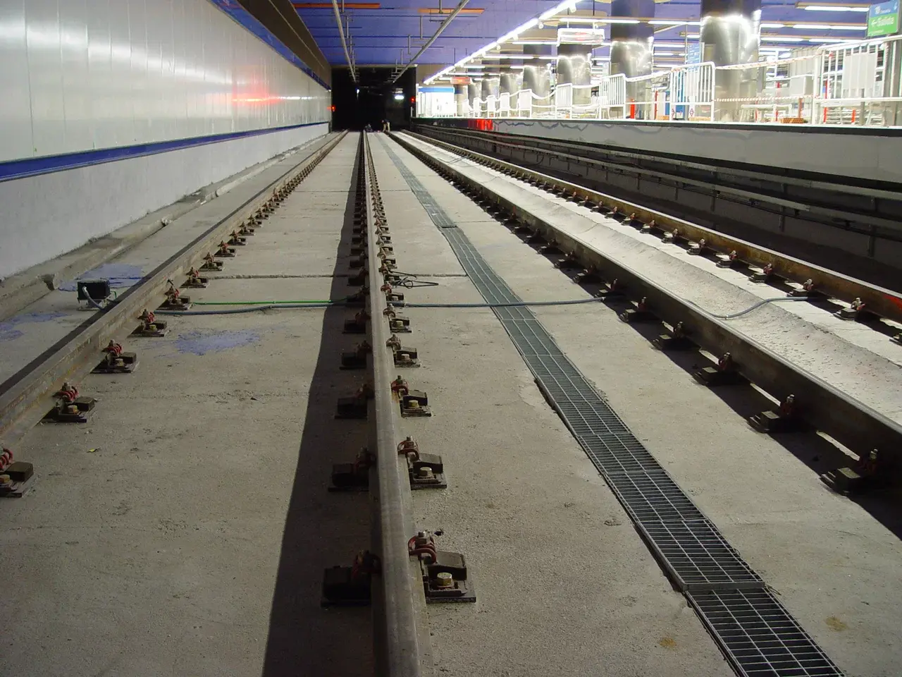
V.2.2. In Stations:
Railway station spaces have experienced a diversification of slab track systems adapted to specific operational and urban integration requirements. The Edilon Embedded Rail system represents the most extended solution in stations, with 2.66 kilometers of implementation. Complementing this solution are various specialized systems: the STEDEF system has been installed in 900 meters, the EDILON EDF-FF modality in 450 meters, the TRANOSA Block system in 450 meters, and finally the DFF system in 900 meters, reflecting the multiplicity of technical approaches available for this operational context.
V.3. Kilometers of Ballastless Track Installed in Spain
V.3.1. On Viaducts:
Implementation on viaduct structures has followed a selective and experimental approach. The DFF system has been installed on 450 meters of Spanish viaducts, constituting a pilot application of this solution. The SFC system represents another deployed alternative, reaching 573 meters, confirming the technical viability of slab systems in elevated structure contexts.

V.3.2. On Cuts/Embankments (Test Sections):
Cut and embankment sections constitute areas where extensive test sections with various slab track systems have been developed, allowing operational experience to be accumulated before decisions on larger-scale implementation. The Edilon Embedded Rail system was evaluated over 432 meters, providing data on behavior in variable terrain contexts. The RHEDA DYWIDAG system reached a similar test length (432 meters) to evaluate its characteristics under these conditions. The RHEDA 2000 system, as a reference solution, was also evaluated over 432 meters of this type of infrastructure. The STEDEF system completed evaluations over 432 meters, allowing technical comparisons under equal conditions. The GETRAC system was likewise tested over 432 meters in these contexts, as was the ATD system, which constituted its validation extension on embankment and cut.
Chapter VI Advantages and Disadvantages
VI.1. Main Advantages
Slab track systems offer a wide range of advantages that make them particularly attractive for specific applications:
Mechanical behavior is characterized by exceptional uniformity of vertical stiffness, combined with strong resistance to lateral forces, providing better stress transmission to the support layers (typical values between 1 and 3 N/cm²). Regarding durability, the service life of the bearing slab reaches approximately 60 years, significantly exceeding that of alternative components, while simultaneously extending the service life of elements such as the rail and the sub-base.
Concerning maintenance, these systems preserve track geometry in satisfactory and practically invariable conditions over time, independently of operating speed, allowing considerable reduction in costs associated with upkeep. Particularly relevant is the decrease in daily intervals dedicated to routine tasks, freeing up capacity for transport operation.
The required total construction height is notably lower than that of conventional ballasted systems. In certain cases, the stiffness allows the transit of vehicles with pneumatic tires. Finally, they significantly improve infrastructure cleanliness and the efficiency of security elements.
VI.2. Limitations and Disadvantages
Alongside the substantial advantages offered by slab track systems, it is important to recognize a series of technical and economic challenges that must be considered in the selection process:
The stiffness of these systems, although advantageous for many applications, can be excessive in some contexts, having a certain negative incidence on passenger comfort at high circulation speeds. Transitions between slab track and conventional ballasted track require careful design and construction, as abrupt stiffness changes generate dynamic reactions and concentrated stresses that can compromise the stability of both systems.
Required construction tolerances are very demanding, with post-construction corrections being difficult to execute given the monolithic nature of these systems. The requirement for “zero” settlement of the support terrain is critical, as the absence of continuous support can lead to localized bending, cracking, and potential failure of the bearing slab. This significantly limits the maximum construction height on embankments (generally between 2 to 5 meters, or up to 10 meters in very favorable circumstances).
Support terrain quality requirements are very stringent, demanding soils of category QS2 or QS3 at minimum, which frequently requires ground improvement works or extraordinary infrastructure works. Support layers under the slab must be constituted with hydraulically bound materials (with cement, gravel-cement, or lime) of at least 30 centimeters thickness, with additionally rigid layers being necessary in the subgrade (sub-ballast with \(E_{v2} > 1.200\) kg/cm² and form layers with \(E_{v2} > 600-800\) kg/cm²).
Investment costs in materials and installation are usually higher than those of conventional track, with significant variability depending on the selected system and project circumstances. Currently, there is a general lack of experience and mechanization of construction processes in many contexts. Times required for incident repairs, although potentially lower during normal operation, can be significantly higher in case of need for structural intervention. Drainage and waterproofing of these systems require ground improvements and special treatments. Finally, acoustic emission can be problematic in long tunnels, with a risk of vibration amplification due to material homogeneity, although mitigating measures exist that can reduce noise even below ballasted track levels.
VI.3. Selection Criteria according to Application Context
The selection of the most appropriate track system must respond to the specific requirements of each application. For operations at speeds exceeding 220 km/h on high-speed lines, recommended systems include RHEDA 2000, VPP, STEDEF, ÖBB, BOGL, and SHINKANSEN, which have demonstrated excellent performance in intense and demanding traffic contexts.
For applications in railway stations, the range of options is wider, allowing selections based on specific circulation and maintenance requirements: direct slab track (EDF, ELASTIPLUS, DFF systems), embedded or jacketed rail (EDILON, CDM), or blocks and boots (TRANOSA, LVT, VIESA).
In contexts where vibration reduction is critical (proximity to urban areas, sensitive installations), floating slab systems with continuous or discrete supports, blocks and boots, embedded rail, direct slab track, and monolithic systems are recommended, depending on the specific characteristics of the project.
For metropolitan transport systems (metros), direct slab track, embedded rail, and blocks or boots are frequently employed, selection being dependent on admissible noise levels, circulation capacity, and space availability.
- Support material requirements and seating layer treatments: Usually require a greater stiffness contribution for slab support, having to configure hydraulically bound layers (with cement HGT-gravel-cement or lime) of at least 30 cm thickness under the slab, and in subgrades also more rigid layers (sub-ballast Ev2> \(1.200 \mathrm{~kg} / \mathrm{cm} 2\) and form layers (Ev2> \(600-800 \mathrm{~kg} / \mathrm{cm} 2\) ))
- Investment Costs in Materials and Installation: Usually higher than those of ballasted track, and very variable depending on the system to be mounted and its location. General lack of experience and mechanization of construction processes.
- Repair times: In principle, incidents on the track system would imply more time than on ballast.
- Drainage and Waterproofing: Require ground improvements (treatments).
- Acoustic emissions: Noise problems in long tunnels, can be accentuated together with ground vibrations due to material homogeneity. Measures (special materials and devices) can be put in place to attenuate it to levels even lower than ballasted track.
VI.2. Ballasted Track Costs
The cost structure of conventional ballasted track can be broken down into specific components, reflecting the construction composition of this consolidated solution. Superstructure elements present unit costs well defined and available in the market: the sleeper plus fastening assembly has a unit cost of 67 euros, the under-sleeper pad contributes 30 euros per unit, while the rail requires an investment of 40 euros per linear meter. Turnouts, specialized elements for track changes, present very variable costs depending on their complexity: type 17000/7300 turnouts reach a value of 740,500 euros, type 10000/4000 turnouts are situated at 644,500 euros, while those of lower complexity type 3000 have a cost of 430,000 euros. The longitudinal track splitter (BLS) constitutes a specialized element with a unit cost of 17,000 euros.
Ballast, a fundamental element of conventional track, requires an approximate quantity of 9 tons per linear meter, with a material cost (placed) of 8.54 euros per ton. Ballast transport from production centers constitutes a significant component, with costs of 0.112 euros per ton and per kilometer of transport distance.
Sleeper fastening systems have detailed technical specifications reflected in their component costs. The AI-04 sleeper fastening, widely used in the Spanish network, integrates various specialized elements with individual costs: the rail pad (PAE 7 mm elastic type) has a unit value of 1.01 euros, with a total of 2 pads per sleeper; light angled guide plates type A-2 are valued at 0.55 euros unit, with two plates required per sleeper (2.20 euros total); screw spikes have a unit cost of 1.16 euros with 4 units per sleeper (4.64 euros total); dowels constitute a component reaching 0.815 euros per unit with 4 dowels per sleeper (3.26 euros total); finally, elastic clips type SKL 1 have a unit value of 1.05 euros with 4 units required (4.20 euros total). The integral cost of the AI-04 fastening is established at 16.32 euros per sleeper, reflecting the complexity of the fixation system.
VI.3. Slab Track Costs
The implementation costs of slab track systems vary significantly according to the selected technological solution and the specific requirements of each project. Detailed analysis of fastening systems for slab track, illustrated in the following graphic documentation, allows these differences to be evaluated.
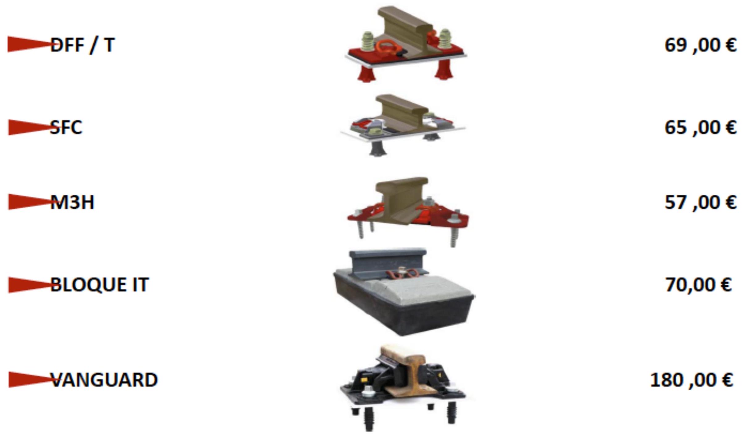
The jacketed rail system constitutes a relatively low-cost solution, with a value of 450 euros per linear meter. This configuration integrates all assembly operations necessary for commissioning the infrastructure.
The prefabricated jacketed rail modality represents a higher initial cost option, situated at 1,000 euros per linear meter. This investment increase is justified by the inclusion of the precast concrete slab in the complete system configuration, which improves construction times and quality assurance in the manufacturing process.
The RHEDA CITY system offers a solution with intermediate cost of 500 euros per linear meter, providing a balance between initial investment and technical capacity.
For applications requiring maximum vibration reduction and greater durability, the floating slab system represents the solution with the highest unit cost, with a value of 1,400 euros per linear meter. This configuration includes a precast concrete slab with a floating isolation system, justifying the significant investment increase.
VI.4. Average Cost Comparison
Ballasted Track
Conventional infrastructure with ballast presents a well-defined and consolidated cost structure in the railway sector. The total platform cost is situated at approximately 4 million euros per kilometer, reflecting needs for ground preparation, drainage, and stabilization. For the superstructure, the average cost reaches 980,000 euros per kilometer, broken down into various specialized components.
Materials constitute 85% of the superstructure cost, reaching 830,000 euros per kilometer. Of this total, the sleeper and its fastening system represent 215,000 euros per kilometer, evidencing its importance in the total cost. The rail contributes 160,000 euros per kilometer, while the ballast (including its placement, compaction, and periodic maintenance) requires an investment of 270,000 euros per kilometer. Turnouts and complementary track devices represent 185,000 euros per kilometer. On conventional lines, the average total superstructure cost approximates 834,000 euros per kilometer.
Slab Track
Slab track systems present cost structures significantly different from the traditional solution. The average total cost of a floating slab system reaches approximately 1,307,000 euros per kilometer, representing a higher initial investment than ballasted track. However, this figure must be contextualized considering the cost composition and investment structure throughout the useful life cycle of the infrastructure.
Breaking down these costs, approximately 927,000 euros per kilometer are destined for slab superstructure components, while 380,000 euros correspond to complementary systems and finishes. This distribution reflects the technical complexity and precision requirements in the manufacturing and installation of slab systems.
VI.5. Maintenance Costs
The integral economic evaluation of track systems must consider, beyond initial investment, operational and maintenance costs throughout the entire useful life of the infrastructure. The higher initial investment in slab track systems can be substantially compensated by significant reductions in conservation and maintenance costs during decades of operation. For this reason, it is essential to evaluate the estimated annual maintenance costs for each superstructure alternative.
This cost analysis must include not only direct conservation expenses, but also economic returns derived from greater infrastructure availability, reduction of unplanned interventions, and externalities generating savings or costs in social and environmental terms. These data constitute the foundations upon which technical-economic criteria for track selection should be based, whether ballast or slab, even considering the possibility of optimizing conventional ballast solutions as a competitive alternative.
Maintenance costs are influenced by multiple factors, including geographical location in relation to material production and transformation centers, homogeneity of the implemented track system, availability of technical means and specialized personnel, and climatic and edaphic conditions of the environment.
International evidence documents considerable variations in maintenance costs depending on the region and degree of implementation of slab track solutions. In Japan, it has been documented that maintenance costs for J-type slab track, used on Shinkansen lines, represent only between 20% and 30% of equivalent maintenance costs on ballasted track. Main interventions in these systems are concentrated on rail grinding and periodic change or substitution of elastic fastening elements.
German experience with the RHEDA 2000 system has demonstrated even more significant reductions, with maintenance costs situated around 10% relative to conventional ballasted track. In this case, the main maintenance activity corresponds to preventive rail grinding to maintain its optimal profile.
For the Spanish context, available technical estimates suggest that the ratio of maintenance costs between slab track and ballasted track would be situated in the range of 40% to 50%, representing substantial savings although lower than those documented in other European and Asian regions. This difference can be attributed to factors such as accumulated experience, availability of specialized resources, and specific characteristics of the national railway network.
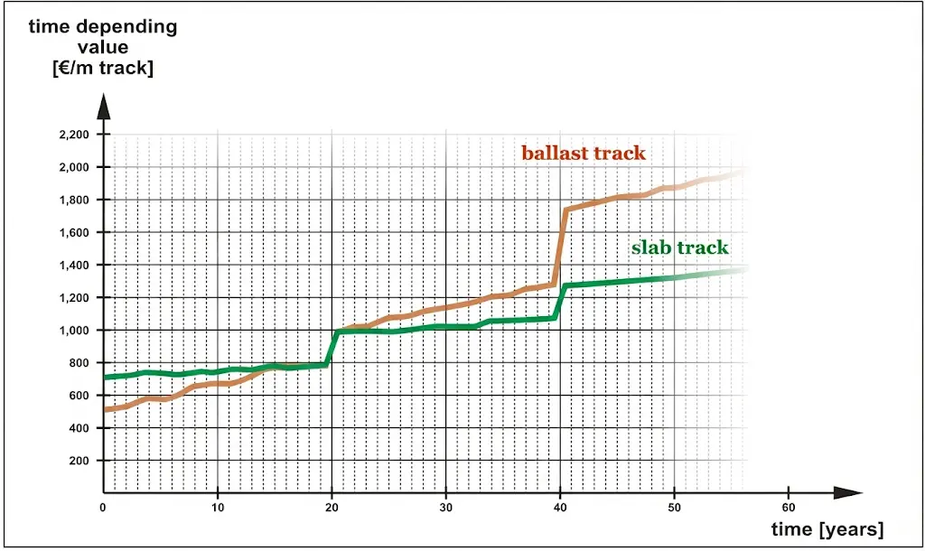
VI.6. Life Cycle Cost
Complete economic analysis of track systems requires an integral cost evaluation throughout their entire operational life cycle. This Total Cost of Ownership approach provides a more realistic perspective of required investment and the economic relationship between track alternatives.
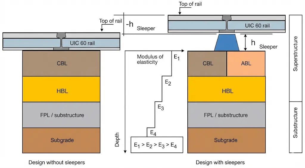
Comparison between ballasted track and slab track systems, considering especially innovation represented by solutions like BB ERS floating slab, reveals fundamental differences in technical-economic parameters. The service life of conventional ballasted track superstructure is estimated at 40 years, while modern floating slab systems reach service lives of 60 years or higher, representing an increase of 50% or more in the operating horizon without complete replacement.
Rail profiles used in both systems also present significant differences. Conventional track employs UIC 60 type rail with an approximate service life of 20 years, requiring multiple substitutions during the total infrastructure life cycle. Conversely, floating slab systems can use specialized profiles like BB ERS, reaching service lives of 36 years, reducing the number of necessary replacements during operation.
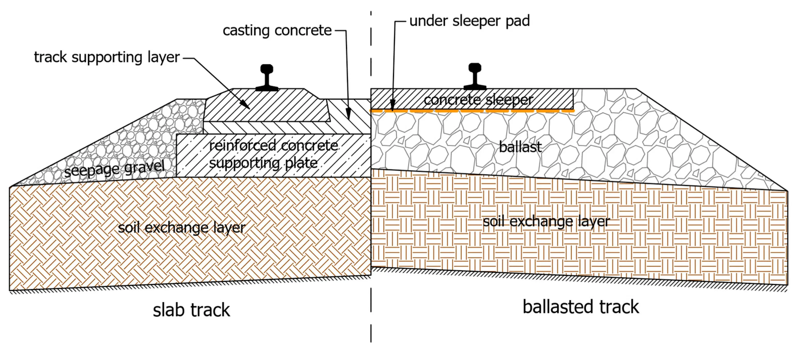
Rail support configuration constitutes another fundamental difference: ballasted track provides discrete support (via spaced sleepers), while slab systems provide continuous support along the entire track length. This fundamental parameter impacts load distribution, component service life, and maintenance requirements.
Regarding track construction, while the conventional solution utilizes ballast as a support and regularization medium, slab systems utilize reinforced or prestressed concrete, providing a base of greater stiffness and durability. The service life of the elastic rail support presents important operational differences: in ballasted track, these elastic elements (washers and seating elements) are renewed jointly with sleepers approximately every 40 years, while in floating slab systems the change of elastic support occurs jointly with the rail, significantly lengthening major maintenance intervals.
For detailed life cycle economic analysis, financial parameters specified according to reference studies have been considered. The interest rate used in economic viability evaluations has been estimated between 4% and 9%, reflecting financing conditions for Spanish railway projects. The inflation rate has been established at 2%, representing a conservative estimate for the last years of the total life cycle analysis horizon.
Technical note: Values presented constitute reference estimates for BB ERS model parameters, serving as a basis for comparative technical-economic analysis in track solution selection.
Review Questions
What fundamentally defines a slab track system versus conventional track?
The substitution of ballast for structural material layers (concrete or asphalt) that provide continuous support and greater stiffness.
What are three main benefits of slab track?
Lower maintenance costs, longer service life (approx. 60 years), and gauge (construction height) reduction.
What distinguishes the Rheda 2000 system from other slab track systems?
It is a monolithic cast-in-place concrete system where sleepers are totally embedded in the reinforced concrete slab.
What main advantage does the floating slab (Mass-Spring Systems) provide?
It provides maximum attenuation of noise and vibrations through the interposition of elastic elements under the slab.
Why are tunnels considered the most favorable environment for slab track installation?
Due to foundation stability, logistical installation ease, and the critical need to reduce maintenance in confined zones.
Bibliography
- Díaz de Villegas, J.M. (2003) Ferrocarriles. Apuntes de clase. E.T.S. Ing. Caminos, Canales y Puertos Santander.
- García Álvarez, A. (2022) Manual de ferrocarriles. El sistema ferroviario español. Ed. Garceta.
- Lichtberger, B. (2011) Manual de vía. Infraestructura, superestructura, conservación, rentabilidad. Eurail Press.
- Villaronte Fernández-Villa, J.A. (2009) Ingeniería y Tecnología Ferroviaria - Tecnología de la vía. Delta Publicaciones.
- Adif: normativa técnica: http://descargas.adif.es/ade/u18/GCN/ NormativaTecnica.nsf