Railway Switches and Crossings
Table of Contents
- Chapter I Introduction
- Chapter II General definitions
- Chapter III Turnouts: Basic principles
- Chapter IV The switch: Function and components
- Chapter V Switch rail profile
- Chapter VI Types of switches and blades
- Chapter VII The crossing (frog)
- Chapter VIII Simplified design of a straight frog
- Chapter IX Turnout laying
- Chapter X Turnouts
- Chapter XI Diamond crossings (travesías)
- Chapter XII Other track devices
- Chapter XIII Other devices
- Chapter XIV Representation of track devices on plans
- Review Questions
- Bibliography
Chapter I Introduction
In the field of railway engineering, the rail transport system presents a continuously distinctive characteristic: railway vehicles operate following a predetermined and fixed trajectory. This particularity is due to the relationship existing between the wheel and the rail, where the guiding element called the flange fulfills an essential function by directing the movement of the rolling stock along the track.
From an operational perspective, the railway infrastructure requires the interconnection of multiple itineraries so that it is possible to execute diverse maneuvers such as crossing tracks, overtaking convoys, parking and shunting transport units, and other essential operations in daily operation. However, all these functions must be performed without the guiding element, the wheel flange, encountering obstructions or impediments in its path.
Historically, the solution to this problem was developed in the year 1796 by the engineer John Curr, who implemented track connection devices in the context of the railway network project for the county of Norfolk in England. These devices constituted a fundamental milestone in the evolution of transport.
THE BEHR MONO-RAIL BETWEEN LISTOWEL AND BALLYBUNION, IN KERRY, IRELAND
During the subsequent centuries, railway technology has experienced a series of technological and design improvements, all of them oriented towards common optimization objectives. The successive advances have pursued three main goals:
- Significantly raise the levels of safety in the operation of railway systems
- Enable the circulation of convoys at increasingly higher speeds
- Considerably extend the durability and useful life of the track devices
Chapter II General definitions
In the context of railway engineering, Switches and Crossings are defined as the set of specialized devices whose function is to guarantee the operational continuity of the railway infrastructure at points where distinct trajectories or itineraries connect. These devices allow maintaining the same level of safety and reliability that exists on a straight and continuous track, enabling the connection and crossing between different lines or branches securely and efficiently.
Switches and Crossings are composed by combinations of only two types of fundamental devices:
-
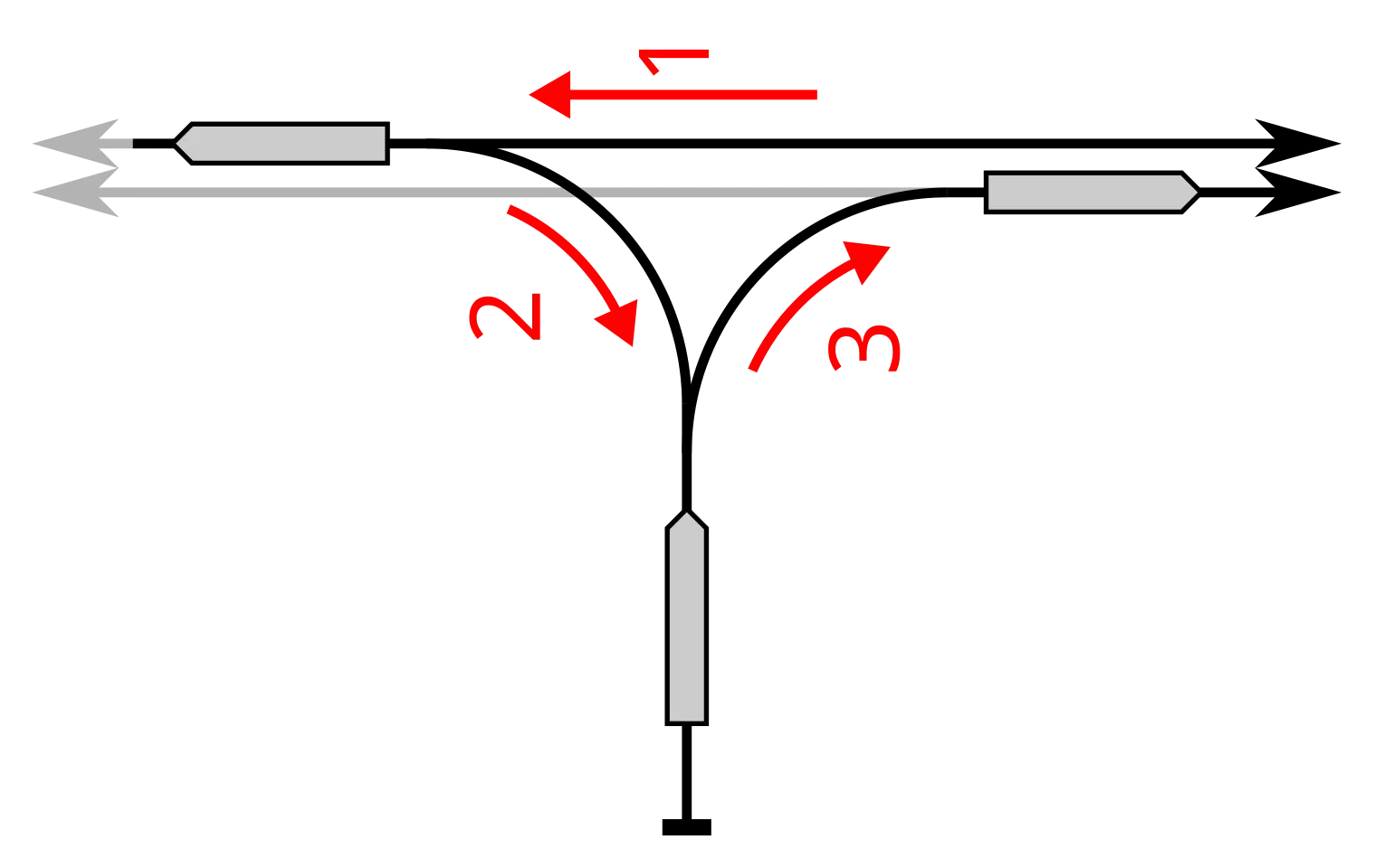
The Turnout: is defined as a specialized track appliance that allows the bifurcation of a railway track into two or more branches, such that the axes of these new tracks converge tangentially with the axis of the main track or form a very small angle with respect to it. This allows the rolling stock to transit smoothly from one trajectory to another.
-
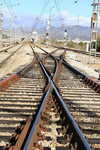
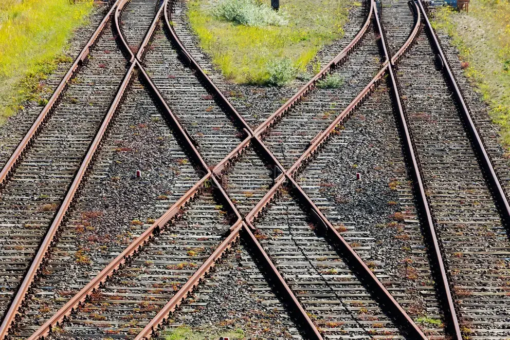
The Diamond Crossing: constitutes a device that facilitates the perpendicular (or oblique) crossing of two distinct tracks. In this case, the axes of both tracks intersect each other, allowing convoys to transit in the four possible directions.
The construction of turnouts and diamond crossings is carried out through the strategic combination of three fundamental structural elements, which are interconnected by segments of conventional track known as closure rails.
These three constituent elements are:
- The Switch: is the component responsible for ensuring the continuity of each of the routes that diverge from the bifurcation point, guaranteeing that the rolling stock follows the correct trajectory according to its position.
-
The Common Crossing (or Frog): allows the intersection of two rail strands corresponding to tracks that cross in opposite directions, so that the wheels can pass from one track to another.
-
The Obtuse Crossing: constitutes a more complex variant that enables the intersection of two rail strands of the same side or hand, allowing for more complex geometric configurations.
Structurally, turnouts are formed by the union of a switch and a simple crossing (common crossing), connected by the previously mentioned intermediate rails.
Diamond crossings, on the other hand, constitute a more elaborate combination formed by two simple crossings (common crossings) and two double crossings (obtuse crossings), which gives them the capacity to allow circulation in multiple directions.
Chapter III Turnouts: Basic principles
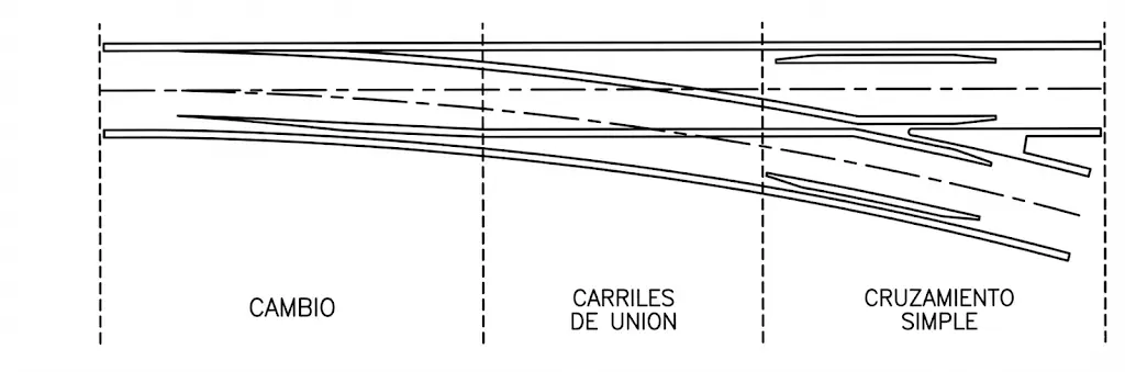
The most elementary configuration of a turnout is the so-called simple or two-way turnout, which provides the convoys circulating through it the alternative of heading towards one or the other bifurcation branch. Conventionally, the track that maintains the continuity of the original direction is called the through route or main line, while the other receives the name of diverging route or turnout track.
The process of separation of both tracks and their subsequent crossing is carried out through the combined action of two previously described elements: the switch, responsible for the separation, and the crossing, which materializes the intersection of the rails.
A simple turnout consists of a series of identifiable components that follow one another in the direction of travel:
-
The Switch: located at the common origin of both tracks, where the bifurcation occurs. In this zone, the four rails that make up the two tracks (two rails of each track) separate in pairs.
-
The Intermediate Rails or Closure Rails: are the segments of track that connect the switch with the crossing, allowing the geometric transition between both elements.
-
The Crossing (Frog): located at the end of the appliance, where the effective intersection of the right (or left) rail of the main line with the left (or right) rail of the diverging line occurs.
Dimensionally, a turnout is delimited by six strategically located joints: the two joints corresponding to the switch mark the toe of the turnout; while the four final joints of the crossing determine the end of the turnout.
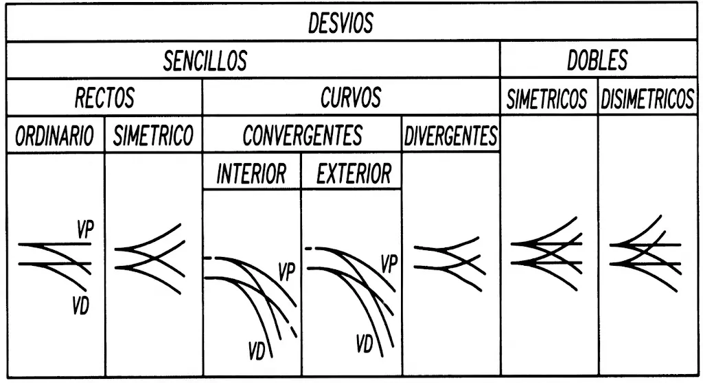
From the point of view of their classification, turnouts can be categorized according to various design and functionality criteria:
Chapter IV The switch: Function and components
The switch is an essential mechanism in the structure of track devices, whose function is to direct the flow of circulation of the convoys towards the specific branch of the track through which they must transit. This component is integrated by several mechanical elements that work in a coordinated manner to achieve this function. The structural components of the switch are described below:
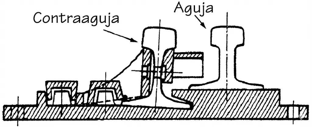
1. The Switch Blades or Tongue Rails (Agujas or Espadines): constitute the movable interior pieces of the switch. They are designed to pivot on one of their ends (the heel), allowing the wheel to be guided towards one side or the other of the track. Their movement is fundamental to redirect the rolling stock.
2. The Stock Rails (Contraagujas): are fixed pieces that are positioned on the exterior of the switch. They work as support surfaces against which the switch blades couple when positioned in their different configurations.
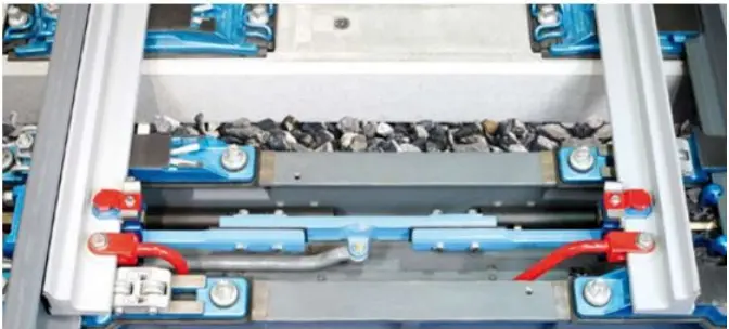
3. The Stretcher Bars (Tirantes): mechanical linking elements that connect the switch blades to each other, ensuring that both move solidarily and simultaneously. Their function is critical to maintain the correct synchronization of the movement.
4. The Locking Devices (Cerrojos): security devices that keep the union immobile between the switch blade and the stock rail. They prevent these pieces from separating during the passage of convoys, avoiding derailments.
Additionally, the switch possesses other mechanical characteristics:
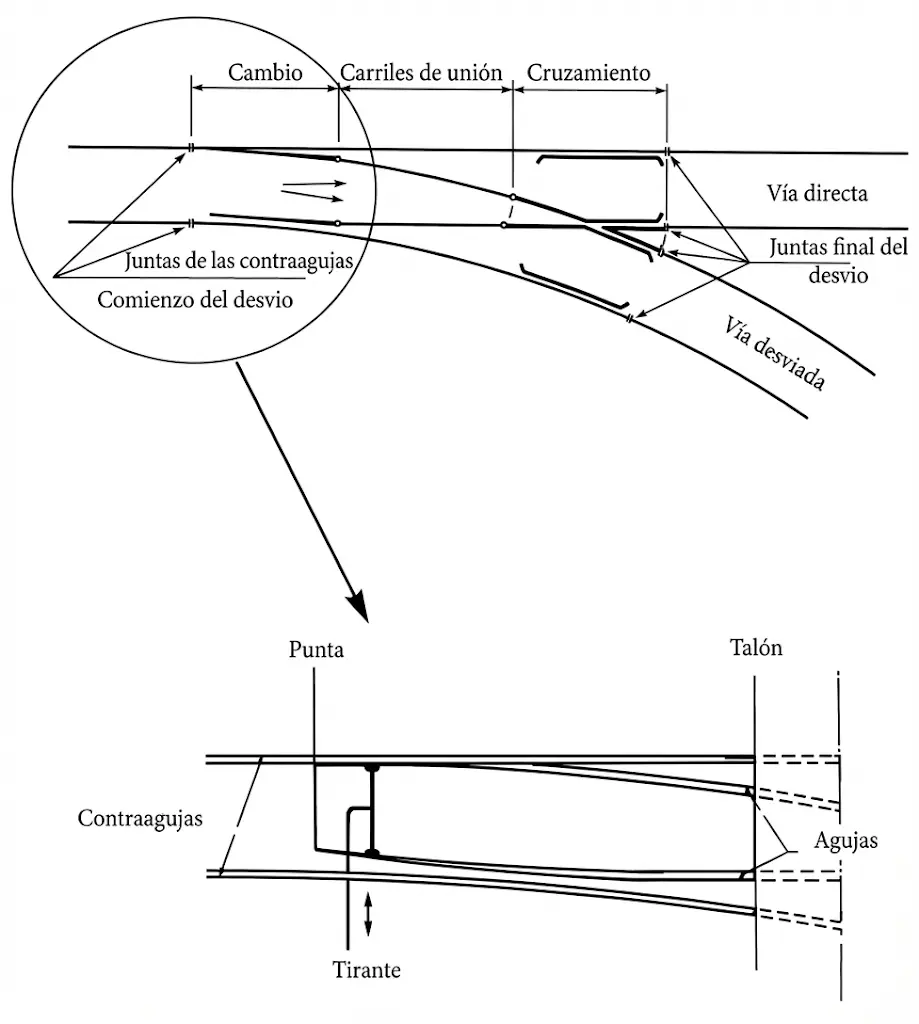
5. The Toe (Punta): is the machined and free region of the switch blade, located at the anterior end. This zone is what effectively guides the wheel towards its correct trajectory.
6. The Heel (Talón): constitutes the posterior end of the switch blade, opposite to the toe. Unlike the toe, this zone is not finely machined and is the point where the switch blade connects with the closure rails that integrate it into the appliance.
The start of the turnout (CD) is technically determined by the joint of the stock rail, not by the toe of the switch blade, which is a fundamental parameter in the design and construction of the devices.
During its operation, the switch blade moves laterally to leave a free path for the wheel flange, allowing the rolling stock to transit without obstacles.
It is important to clarify that in representation diagrams, the thicker lines do not represent the theoretical axes of the rails, but the gauge face (active edge) of each of them. The gauge face is defined as the line located on the lateral face of the rail (called running edge) that has potential contact with the wheel flange to perform its guiding function, located at a depth of \(\mathbf{15 ~ mm}\) below the upper edge of the rail.
Geometric and functional definitions of the switch:
-
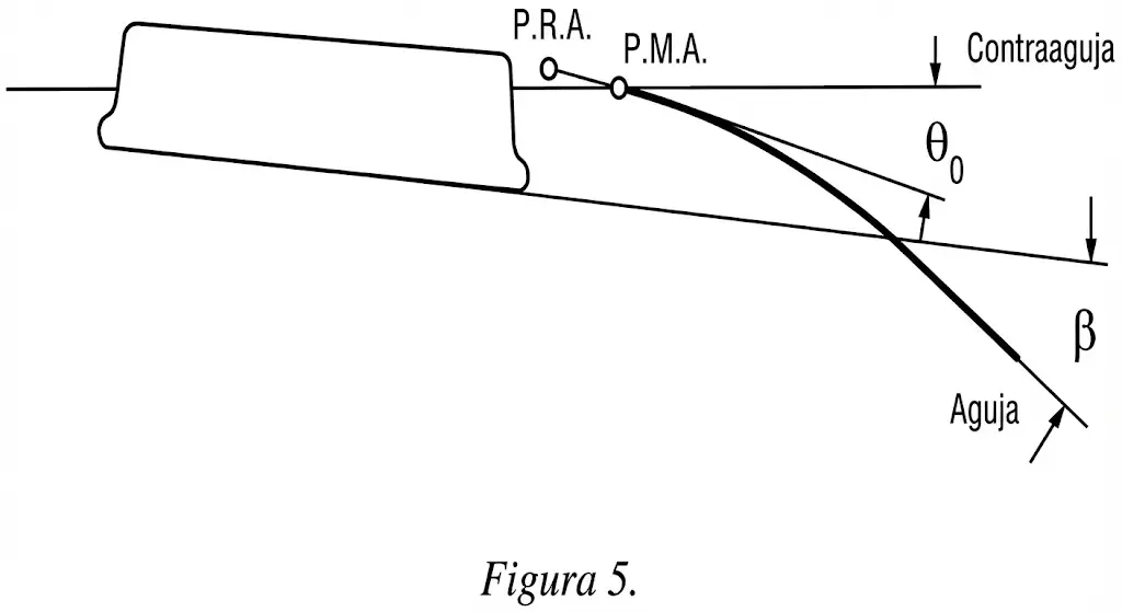
Theoretical Point of Switch (PMA - Punta Matemática): represents the theoretical point of convergence of the gauge faces of the elements that make up the switch, that is, where the gauge faces of the switch blade and the stock rail would geometrically intersect.
-
Actual Point of Switch (PRA - Punta Real): constitutes the physical and material end of the switch blade as it is manufactured and installed.
-
Switch Angle (θ): is the angular parameter that characterizes the geometry of the switch, representing the angle formed between the two gauge faces at a specific point of the switch blade geometry.
-
Angle of Attack (β): defines the angle at which the axle (wheelset) of the rolling stock encounters and comes into contact with the gauge face of the switch blade.
Switch Actuation System:
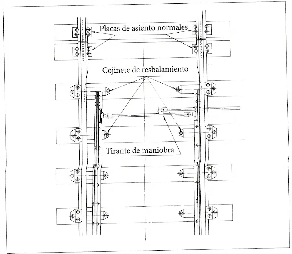
Switch blades can be actuated by various technological procedures adapted to different operational needs: manual systems using levers, mechanical systems with rigid connections, hydraulic systems with pressurized fluids, or electric systems with low-voltage motors. These systems can move the blades simultaneously or with small controlled time intervals. Once the switch blade couples correctly with its stock rail, immobility is maintained by a locking device called a lock or clamp. During their displacement, the blades slide on special lubricated surfaces called slide chairs or slide plates, until they adapt perfectly to their resting position.
Standard switches operate with the following technical parameters:
| Parameter | Value |
|---|---|
| Maximum trailing speed | 40 km/h |
| Permissible modification of blade length due to temperature change | +/- 35 mm |
| Rail profiles | Appropriate for all types of commonly used rail |
| Track gauges | Can be used independently of track gauge |
Operationally, it is established that simultaneously, except during shunting operations, one of the switch blades must be coupled and in full contact with its stock rail, while the other must be open and separated.
 Specific Actuations of the Switch:
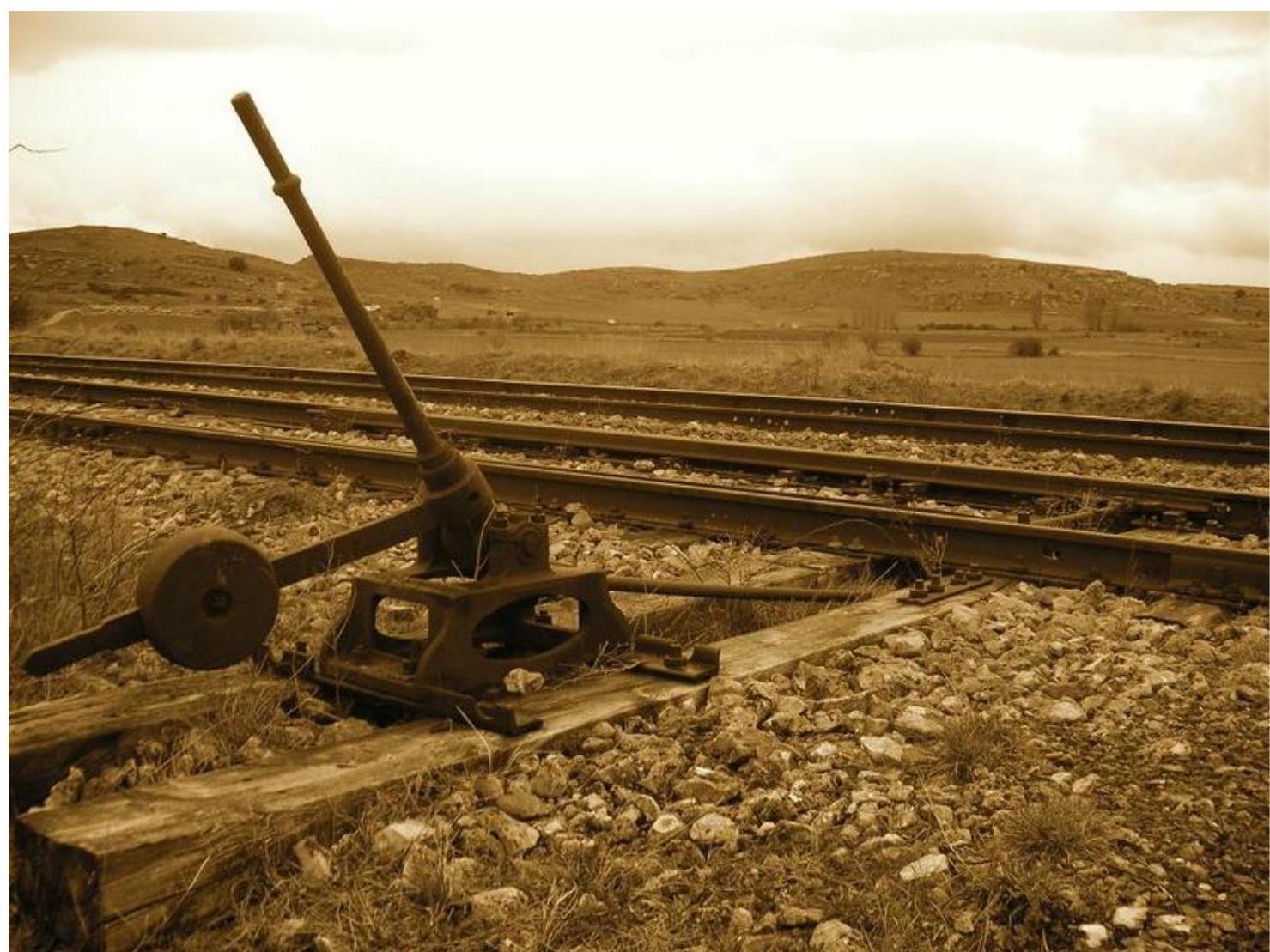
Switches can be operated manually by means of a lever located at the foot of the appliance, which acts on the maneuvering mechanism of the blade. Depending on their configuration, these levers may have a single equilibrium position (single effect) or two distinct positions (double effect). In double-effect systems, special counterweights (colloquially called “cheeses”) are used to automatically determine the position of the blades.
For remote operation, there are different transmission systems: rigid systems based on articulated metal elements; funicular systems using tensioned cables; fluid transmission systems using compressed air or pressurized water; and electrical systems controlled by low-voltage motors.
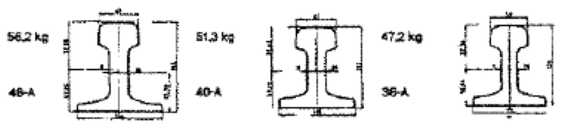
Chapter V Switch rail profile
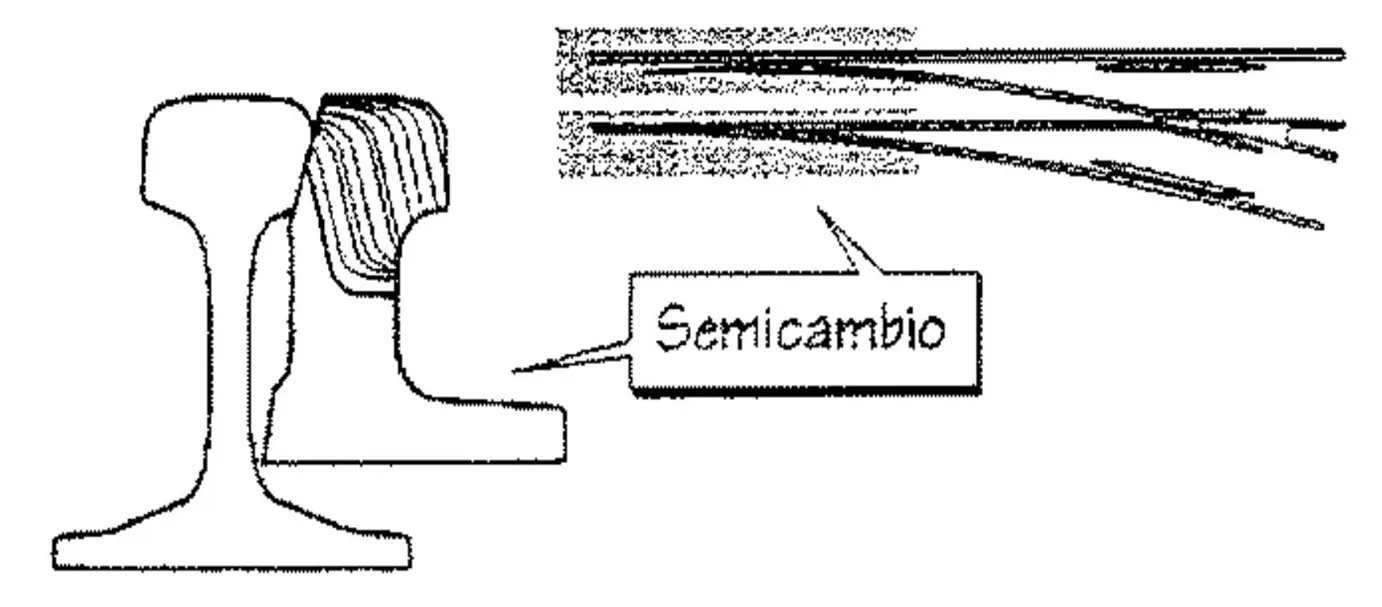
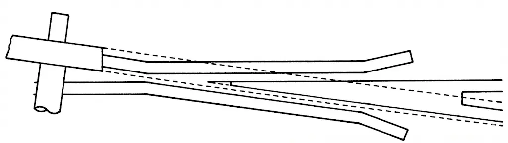
Historically, the manufacture of switch blades was carried out through machining processes of ordinary rails, where both the head and the foot of the rail were planed appropriately to obtain the specific required geometry.
In the railway industry, although experiments have been made at some point with Brunel rail (visible in the attached figure), the standard practice is to use Vignole rails, which are conventional flat-bottom rails, but with wider web sections that provide greater rigidity and mechanical resistance.
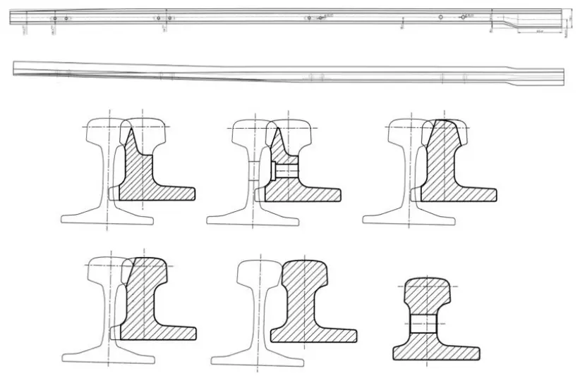
Classification of Switch Blade Profiles:
The variety of switch blade profiles currently existing in the international market can be organized into three main categories, each derived from different schools of railway engineering:
- High Symmetrical Profile: developed based on French railway technology.
- Low Symmetrical Profile: also coming from the French engineering tradition.
- Asymmetrical Profile: coming from the technology of German and Austrian railways.
The following figure systematically compares these three profiles with the normal rail profile used in conventional tracks:
 High Symmetrical Profile
 Low Symmetrical Profile
 Asymmetrical Profile
Criteria for Selection of Rail Type:
In the engineering design process and selection of the most suitable profile for a specific application, the following technical and operational aspects must be carefully considered:
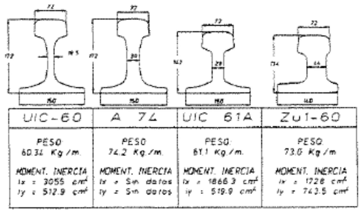
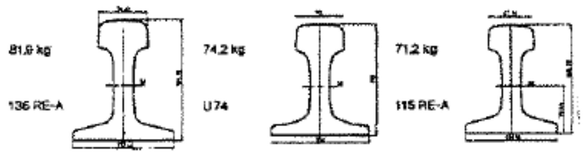
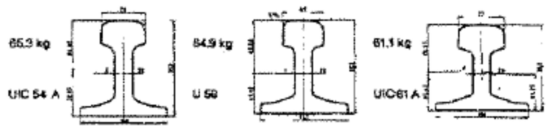
V.1. TRANSVERSE RIGIDITY
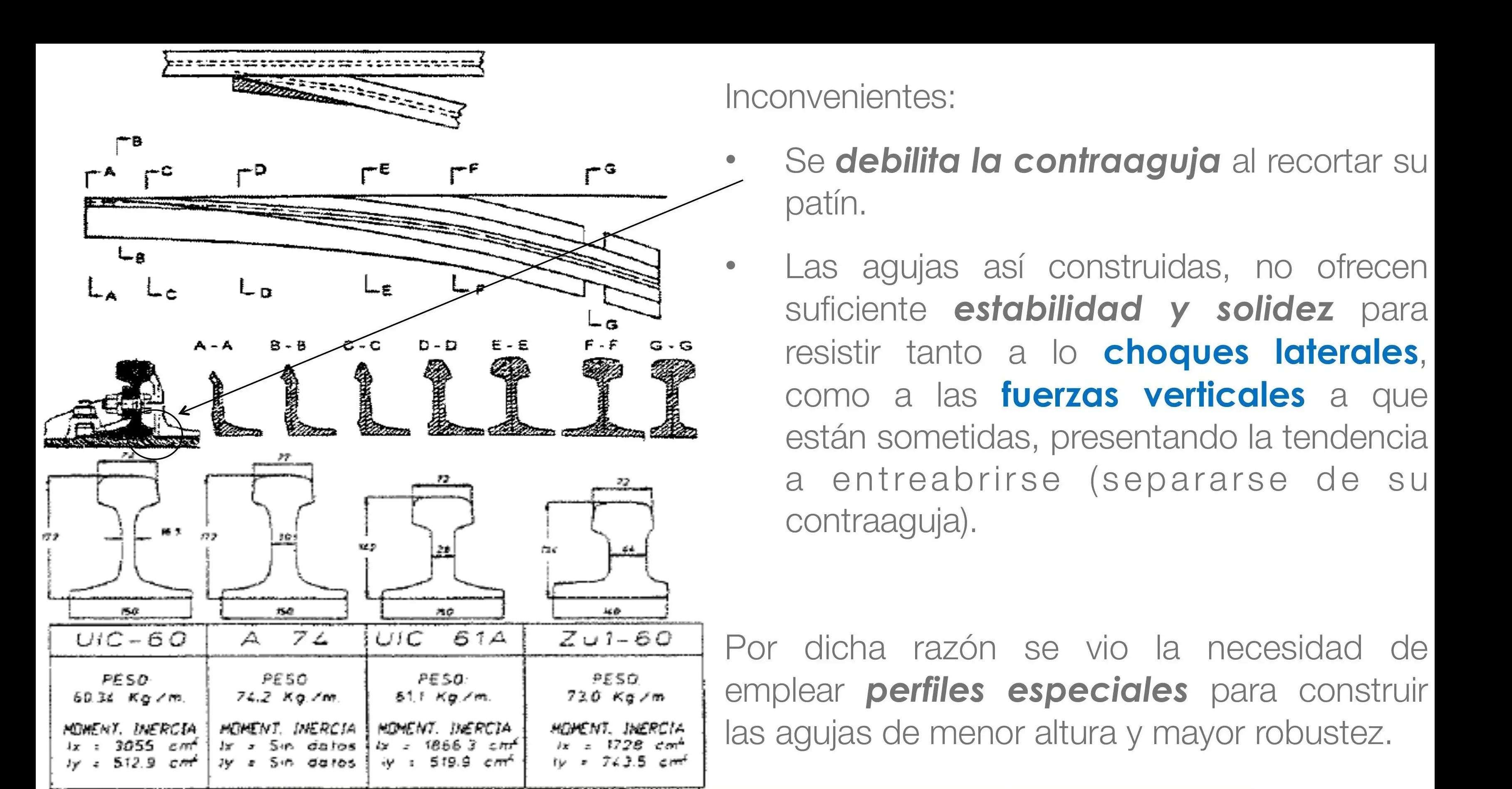
The transverse rigidity of the rail constitutes a parameter of crucial importance due to the forces and stresses exerted by the wheel flange when the vehicle axle enters the diverging track, particularly during the trailing maneuver. The transverse moment of inertia, designated as Iy, must possess sufficient magnitude to ensure that the switch blade does not experience plastic deformation and does not tilt or twist during its operational movement.
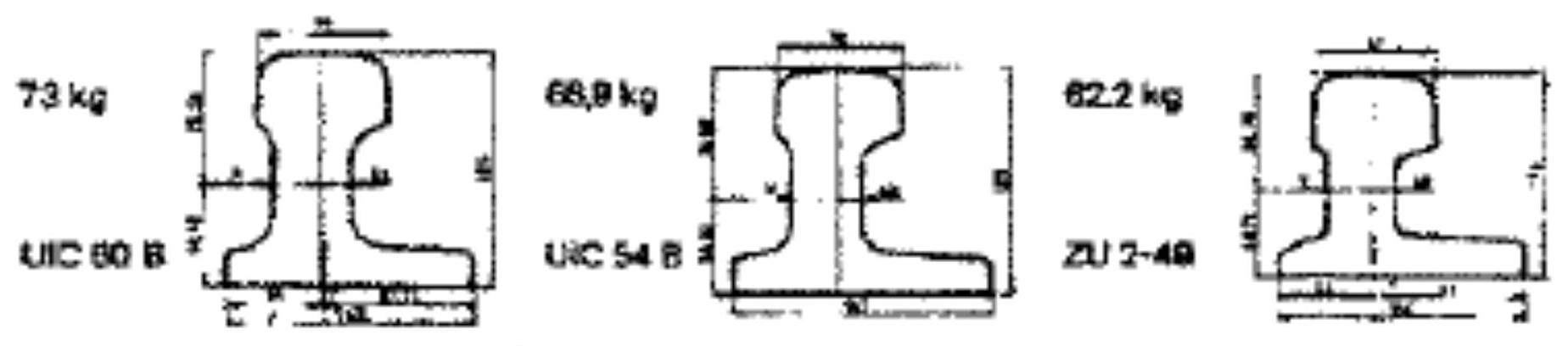
V.2. MAINTENANCE OF THE FLANGEWAY GAP (SWITCH BLADE-STOCK RAIL)
The correct functionality of the switch requires that when the blade is in the open position, there is no contact between the movable guide and the wheel flange of the vehicles. To achieve this, it is necessary to maintain a minimum separation between the open blade and its adjacent stock rail. This value, called r, is a function of several parameters: B (standard distance between the inner planes of the wheels), e (nominal thickness of the flange), and G (track gauge), according to the relationship:
\[r>G-(B+e)\]When performing these calculations, it is fundamental to apply all tolerances in the most unfavorable sense, in addition to considering the possibility of lateral wear of the rails throughout the operating life.
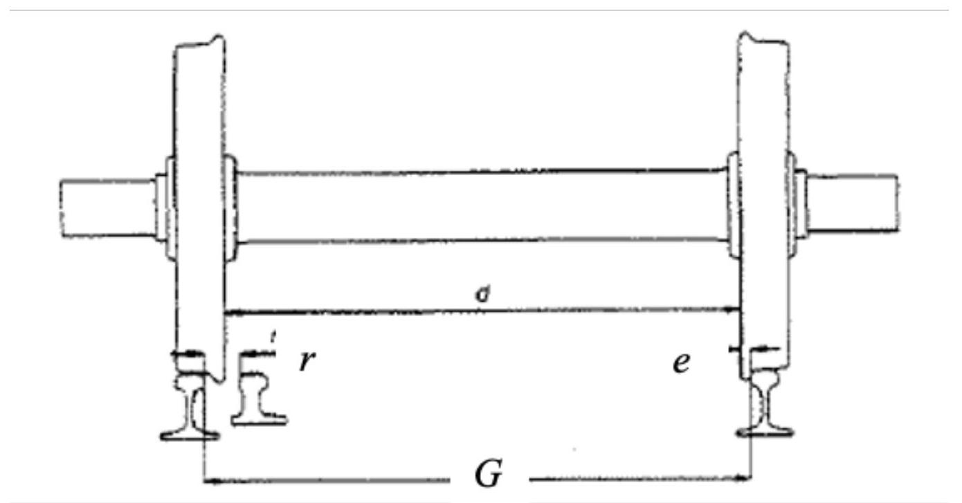
Values typically employed in practice are in the range of: \(r=55-65 \mathrm{~mm}\).
For specialized switches in high-speed systems, maintaining the required separation demands the installation of multiple actuation points distributed along the switch, since the inherent flexibility of longer blades does not guarantee by itself the maintenance of this critical dimension. Consequently, the Transverse Rigidity of the rail (Iy) becomes particularly important in these applications.
V.3. INCLINATION OF RAILS IN THE SWITCH
In conventional railway tracks, rails are installed with an inclination relative to the vertical directed towards the interior of the track, typically 1:20. However, this practice varies according to the railway administration:
- British, German, and Austrian Railways: maintain an inclination of 1:40
- Some US companies: use inclinations of 1:100 or even completely vertical rails
Justification for the 1:20 inclination:
The adoption of the 1:20 inclination responds to several technical and operational reasons:
-
Vertical positioning of the rail produces oblique wear of the running surface consistent with the inclination of wheel treads, causing crushing of the lower zone of the rail head and formation of burrs.
-
Abnormal wear pattern of the tires is observed, with the formation of a groove in the vicinity of the flange.
-
There is a tendency for rails to overturn outwards and an increase in stresses on the outer rail on fastenings and sleepers, especially in tight curves, resulting in a deterioration of the general alignment of the track.
Constructive Solutions in Switches:
In the switch zone, the blade must be placed vertically to facilitate its smooth displacement over the slide chairs. For this reason, designers must choose between two constructive configurations, each with specific advantages and disadvantages:
Vertical Stock Rail: has the advantage of allowing the use of simple slide chairs with a horizontal slide plate. To achieve this configuration, it is necessary to perform a transition of the rail from its 1:20 inclination to completely vertical. This transition is effected through sets of special variable inclination base plates that progressively rotate the rail along 3 or 4 sleepers, so that the angular change is gradual and uniform on each sleeper.
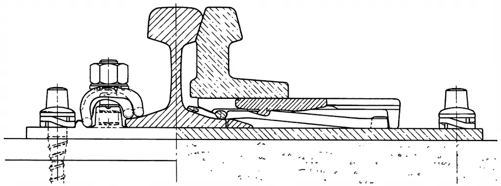
Inclined Stock Rail: presents the advantage of not modifying the running plane of the vehicles (an effect that is especially significant at high speeds) during the passage of the train through the main line of the switch, which is the most frequently used trajectory. The drawback lies in the constructive complexity of the slide chairs. A technically elegant, although expensive, alternative is to use stock rails placed vertically but manufactured with a special profile whose web presents a 1:20 inclination.
V.4. PROBLEM OF JOINING AND MATCHING AT THE HEEL OF THE SWITCH BLADE
Connecting the profile of the switch blade with the closure rails presents different degrees of technical difficulty depending on which type of profile is used:
High Symmetrical Profile: the solution is relatively simple. It is sufficient to machine the desired special profile and execute a twisting operation in case the normal profile is inclined (as described in the previous point).
Low Symmetrical Profile: this configuration requires forging the heel of the blade to perform the transition from a low symmetrical section to a higher section that adapts to the intermediate rails. This union is typically made by aluminothermic welding.
Asymmetrical Profile: this option presents the greatest constructive difficulties, since it is necessary to forge the heel to create a transition between geometrically very different sections.
V.5. EASE OF ROLLING
From the perspective of manufacturing processes, symmetrical profiles present more favorable characteristics for hot rolling. Asymmetrical profiles, on the contrary, present greater complications in straightening operations subsequent to rolling.
V.6. NEED TO REDUCE MANEUVERING EFFORT
The process of flexing the switch blade in the vicinity of its heel requires the application of significant mechanical effort. For this reason, in zones where this flexion is concentrated, machining of the rail foot is typically performed, reducing its thickness over a length of approximately one meter.
V.7. EASE OF DESIGN OF THE SWITCH BLADE-STOCK RAIL ASSEMBLY
Lower profiles (symmetrical or asymmetrical) allow maintaining the complete geometry of the stock rail, especially preserving the full integrity of the foot. This characteristic even facilitates the possibility of establishing elastic inner fastenings for the stock rail, through systems housed inside the slide plate. This allows maintaining the elasticity properties characteristic of normal track even inside the switch, a function that is not achievable with high symmetrical profiles, where it is necessary to machine the inner feet of both pieces. In these cases, to maintain the stability of the stock rail, rigid fastenings traversing the web of the profile are required.
Chapter VI Types of switches and blades
Track appliance engineering contemplates diverse classifications of switches and blades based on functional, structural, and operational criteria.
VI.1. ACTUATION
Operation at the appliance (Manual): Switches can be manipulated manually by means of a maneuvering lever located at the site of the appliance itself. This lever acts directly on the transmission mechanism of the blade. Depending on their mechanical configuration, these levers may possess a single equilibrium position (called single effect) or two differentiated positions (double effect). In double-effect switches, special counterweights, colloquially called “cheeses”, are used to stabilize and automatically determine the resting position of the blades.
Remote Operation: For applications where remote control is required from centralized maneuvering posts, multiple transmission technology alternatives exist:
- Rigid Transmission: based on articulated metal elements that transmit movement directly and mechanically.
- Funicular Transmission: (Wire-worked) uses tensioned steel cable systems to transmit control forces.
- Fluid Transmission: takes advantage of compressed air or pressurized water as energy transmission media.
- Electrical Transmission: employs low-voltage electric motors that actuate the switch mechanism.
VI.2. MOVEMENT OF VEHICLES
In terms of the movement of rolling stock through switches, these can be taken from different directions, which entails different safety considerations:
A switch can be transited from the switch zone itself (facing points), in which case the rolling stock takes the direction imposed by the current position of the blades. Alternatively, the convoy can enter from the heel of the switch (trailing points). If the maneuver has been executed correctly, the train will find the path clear to circulate accordingly. However, if the maneuver was not performed adequately and the switch remains in a closed configuration for that specific itinerary, the wheel flanges will enter the space between the blade and the stock rail, forcing their separation and breaking the stretcher bars that maintain the correct separation between both pieces.
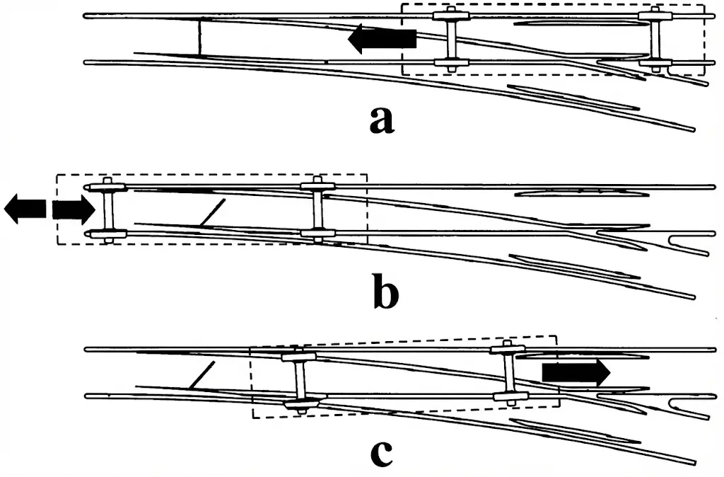
This event, where rolling stock forces the opening of a switch that was not prepared to receive it from that direction, is called trailing through (talonamiento). The process begins with the deformation or rupture of the stretcher bars, followed by the forced separation of the blades.
Trailing through an ordinary switch does not necessarily produce Immediate derailment of the train causing it. However, if the convoy attempts to reverse after trailing through, especially if it has not completely cleared the turnout, a derailment can occur. This situation is particularly dangerous if the convoy has part of its vehicles on the main line and another part on the diverging line of the switch. This type of accident usually happens due to operational errors by agents in charge of shunting in stations. In certain types of railways of lesser importance or reduced traffic, there are special switches called trailable switches. These switches are designed so that a spring or counterweight automatically returns the blades to their original position after the rolling stock that trailed through has passed the appliance. The blades in this type of configuration operate independently of one another.
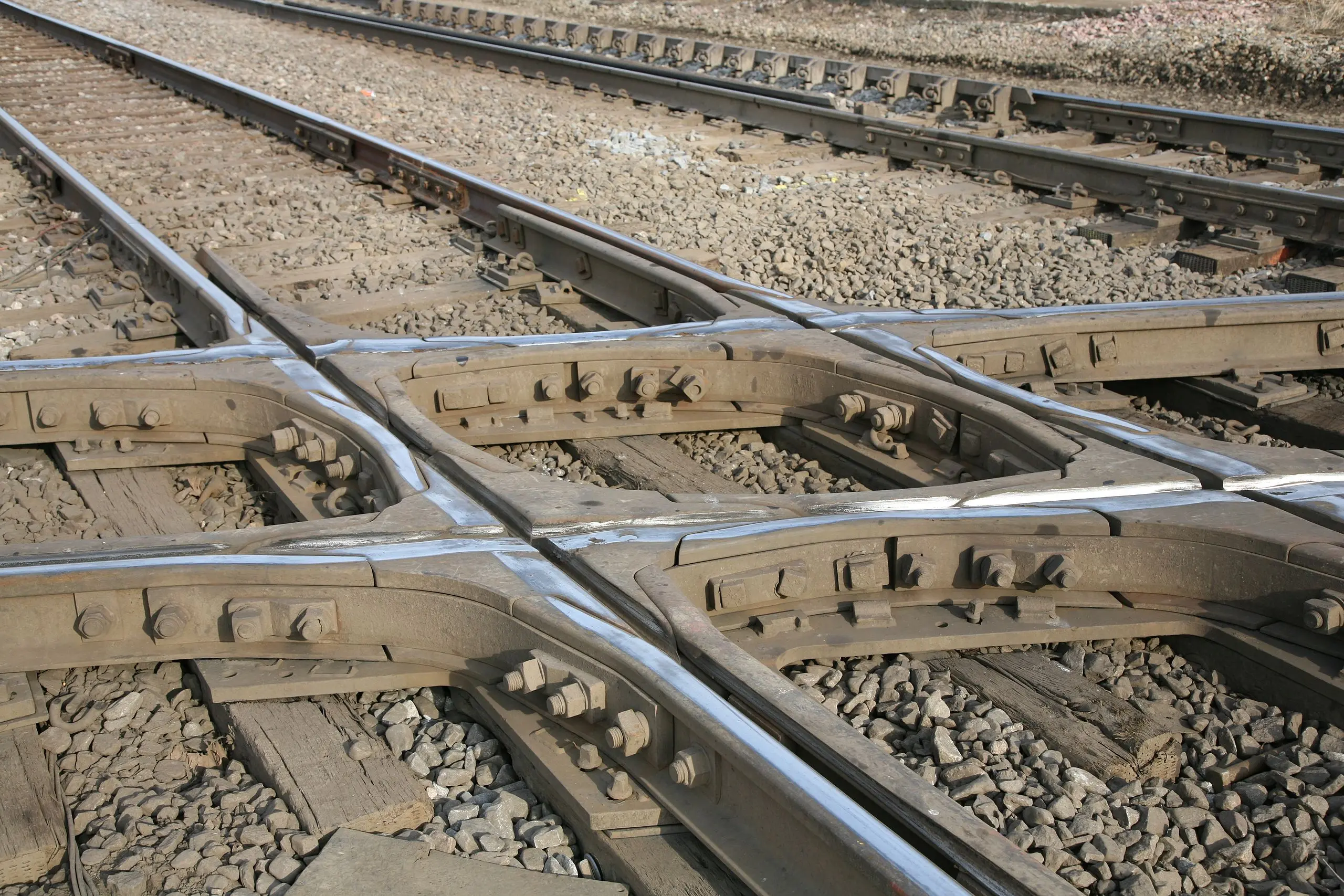
Chapter VII The crossing (frog)
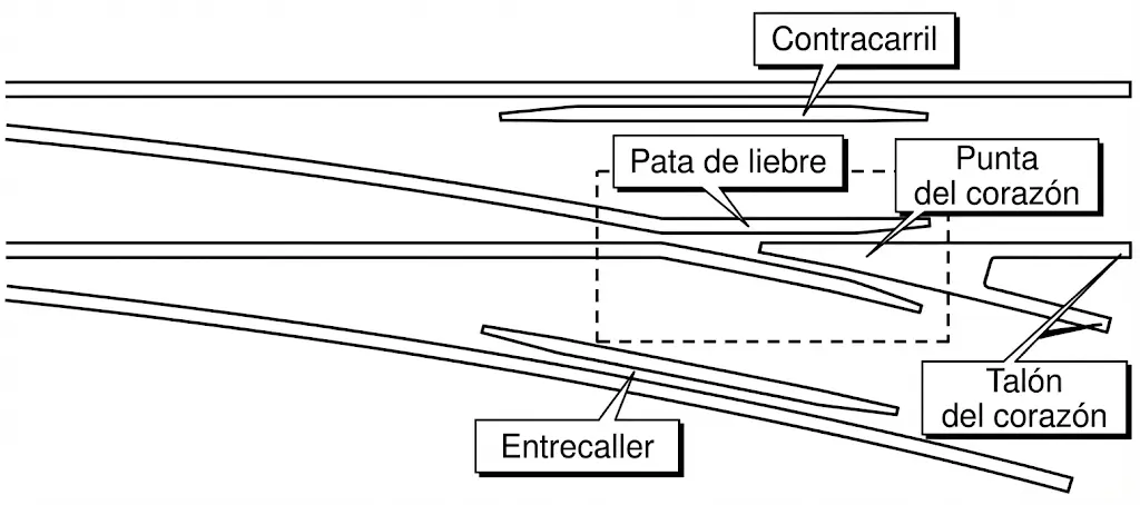
The crossing (or frog) represents the most complex and critical component of the turnout, being the place where the geometric superposition of the two railway itineraries occurs. Its structure consists of three fundamental components: the crossing nose/point (common crossing), the check rails, and the wing rails.
The Heart of the Crossing (Frog):
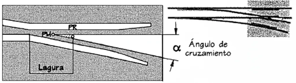
The frog is defined as the constructive zone where the physical union of the two intersecting rails occurs. The threads of the main line and the diverging line form, upon mutually cutting, the characteristic line called point of the frog (nose). The point PM (Theoretical Point of Intersection) marks the theoretical and ideal position where both rail threads would geometrically intersect; the point PR (Actual Point of Crossing) materializes the effective physical position where the union of the two rails begins. The active point of the frog is usually slightly lowered or shaped to achieve a smooth and gradual ascent of the wheel over this critical zone.
The frog constitutes the most stressed zone of the crossing, as it continuously receives the impacts of vehicle wheels during the passage of convoys. The heel of the frog is the end of this zone that coincides with the end of the turnout.
Constructive characteristics for safe passage:
To allow the transit of wheel flanges without causing damaging contact with the frog, it is necessary to introduce a strategic discontinuity in both rails, creating an empty space called the gap (laguna). This discontinuity is essential for the functionality of the appliance.
Wing rails (patas de liebre) are the special extensions presented by adjacent rails in the frog zone, with the purpose of providing mechanical support to the wheel tread when it rolls externally on the outer edge of the tread during the passage of the flange through the gap.
The spatial separation between the active faces of the frog and the corresponding wing rail, or between check rail and running rail, is called flangeway or flangeway gap. This parameter is critical for operational safety.
Function of Check Rails:
Check rails (contracarriles) constitute specialized structural elements whose function is to guarantee the bidirectional guidance of the axle wheel traversing the critical zone of the frog, passing over the gap. Their presence is essential to prevent vehicle derailment and to protect the integrity of the frog against accelerated damage. Both check rails and wing rails present openings at their entry ends, designed to gently channel approaching wheels, thus avoiding destructive frontal shocks that could damage the pieces.
VII.1. DEFINITION OF A CROSSING
Crossings and the turnouts of which they form part are fundamentally characterized by the crossing angle (α), which represents the angle formed by the two threads of the tracks that intersect. This parameter is also known as the frog angle. In curved frogs, where geometry is more complex, this angle is defined as that formed by the tangents to the threads at the heel of the frog.
In professional practice, it is not common to define a crossing or turnout by its crossing angle expressed in degrees, but rather by the value of the tangent of said angle. This tangent can be expressed numerically (for example, 0.11) or by a 1:n type relationship that is easier to remember and use (for example, 1:9). In certain railway administrations, the number n is called the turnout index or turnout number.
Values most commonly used by the Spanish administration ADIF are as follows:
| TANGENT OF ANGLE | Ratio | n | CROSSING ANGLE |
|---|---|---|---|
| 0.075 | 1:13 | 13 | \(4^{\circ} 17^{\prime} 21^{\prime \prime}\) |
| 0.09 | 1:11 | 11 | \(5^{\circ} 8^{\prime} 34^{\prime \prime}\) |
| 0.11 | 1:9 | 9 | \(5^{\circ} 16^{\prime} 38^{\prime \prime}\) |
| 0.13 | 1:7.5 | 7.5 | \(7^{\circ} 35^{\prime} 41^{\prime \prime}\) |
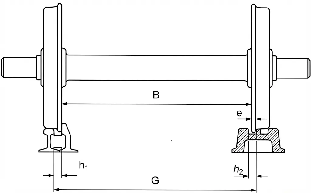
Check Rail Design Criteria:
From an operational safety perspective, check rails fulfill the specific function of guiding the axle when it traverses the frog gap. Considering the geometric scheme represented in the figure, for the wheel passing over the frog not to adopt an incorrect trajectory nor crash against the point of the frog, the following condition must necessarily be met:
\[\mathrm{G}-\mathrm{h}_{1}=(\mathrm{B}+2 \mathrm{e})-\mathrm{e}=\mathrm{B}+\mathrm{e}\]From which it is deduced that:
\[h_{1}=G-(B+e)=G-m\]Where m is known as the minimum protection dimension of the frog point, being a fundamental parameter in the calculation and design of crossings.
Chapter VIII Simplified design of a straight frog
In the design development of a crossing, one starts from the knowledge of the tangent of the crossing angle tg(α), from which the remaining geometric elements defining the structure can be calculated and determined.
The total length of the frog Lt is determined as a function of the minimum opening b necessary to perform bolting and correct connection with the adjoining rails, with c being the width of the rail profile used.
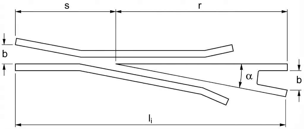
Fundamental geometric parameters are calculated using the following expressions:
\[\begin{aligned} s & =\frac{b}{\tan \alpha} \\ r & =\frac{b+2 c}{\tan \alpha} \\ L_{t} & =\frac{2(b+c)}{\tan \alpha} \end{aligned}\]Curved Frogs:
In addition to traditional straight frogs, there are more sophisticated geometries capable curved frogs, where the active edges of the frog present a continuous curvature instead of straight lines. Compared with straight frogs of equal crossing angle, these curved frogs allow a larger radius for the trajectory of the diverging track, which enables operation at higher speeds, significantly improving the performance of the track appliance.
Chapter IX Turnout laying
The seating and fixation of track devices are carried out using special structural elements called bearers or long sleepers (riostras/longrinas), which present greater length and cross-section compared to ordinary track sleepers. These elements have the critical function of distributing and transmitting the concentrated stresses derived from the passage of rolling stock towards the support platform, in addition to considerably strengthening the entire structure of the appliance.
From the perspective of construction materials, bearers manufactured in wood are preferred as they allow being easily notched and drilled according to the specific requirements of each type of appliance and its particular geometry.
In more recent times, it has been observed that prestressed concrete bearers are becoming progressively competitive from technical and economic points of view. This trend is mainly due to their greater specific weight significantly increasing the stability of the track in the appliance zone, providing operational advantages in terms of resistance to lateral and torsional forces.
Chapter X Turnouts
X.1. SPEED THROUGH TURNOUTS
Speed on the through route (Direct Track):
The transit of convoys through the main line of a turnout does not present additional limitations related to the geometry of the appliance, the only restrictions being those of general dynamic origin of the railway line. This characteristic constitutes an important operational advantage, as it allows maintaining high speeds in the preferred direction.
Speed on the diverging route:
On the contrary, passage through the diverging track presents significant limitations and is subject to restrictions established by technical standards (NRV 3-6-0.0) based on the specific geometric characteristics of each turnout. On RENFE gauge lines, the maximum permitted speed through the direct track is:
- Type A Turnouts: 140 km/h
- Type B Turnouts: 160 km/h
- Type C Turnouts: 200 km/h
- AV Turnouts (International gauge): 250 km/h
For transit through the diverging track, the maximum speed is limited by the centripetal acceleration that the vehicle would experience in the curve, according to the following formulation:
\[\left.\begin{array}{l} a_{c}=\frac{v^{2}}{R} \leq 0,65 \quad \mathrm{~m}/\mathrm{s}^{2} \\ v^{2}=\frac{V^{2}}{3,6^{2}} \end{array}\right\} \Rightarrow V \leq 2,9 \sqrt{R}\]Where V is speed in km/h and R is the radius of the curve in meters.
X.2. TURNOUTS FOR HIGH SPEED
Track devices in high-speed systems represent the most complex elements of the entire railway superstructure, because they concentrate multiple sources of discontinuities that generate important dynamic stresses:
-
Direction discontinuity: there is an abrupt discontinuity in the direction of the track axis when traffic takes the diverging track, generally without the presence of a progressive transition curve.
-
Acceleration discontinuity: this direction discontinuity translates directly into a discontinuity in accelerations and jerks experienced by vehicles, aggravated by the impossibility of establishing adequate superelevation (cant) in the diverging track.
-
Discontinuity in rolling support: finally, and especially in high-speed systems, there is a significant discontinuity in wheel support when transiting the critical zone of the crossing, experiencing a transition from the wing rail to the point of the frog, or vice versa, traversing the gap.
Any discontinuity in the running surface generates important dynamic stresses between the rolling stock and the infrastructure. The magnitude of these stresses grows notably with circulation speed, which is why the problems described above are especially critical and demand sophisticated solutions in High-Speed turnouts.
Innovative Constructive Solutions:
To specifically address the problem of the gap in High-Speed crossings, when high axle loads are present or great traffic intensity is required, two innovative designs have been developed that effectively eliminate this discontinuity:
Swing Nose Crossing (Corazón de punta móvil): Its operation is based on a principle similar to that of the switch, where a movable point couples to a fixed stock rail (knuckle). The movement of the frog point is performed taking advantage of its inherent flexibility, facilitated by the presence of a strategically located lateral joint. This system eliminates the gap by allowing the point to accompany the passage of the wheel.
Movable Wing Rail Crossing (Corazón de patas de liebre móviles): In this solution, the two wing rails move simultaneously by means of a coordinated mechanism, creating a flangeway on one side to allow the passage of the wheel flange, while simultaneously suppressing it on the other side. This ensures continuity in the running surface.
X.3. IBERIAN GAUGE
Turnouts for Iberian gauge (1.668 m) are classified into different types according to their operational capacity and technical characteristics:
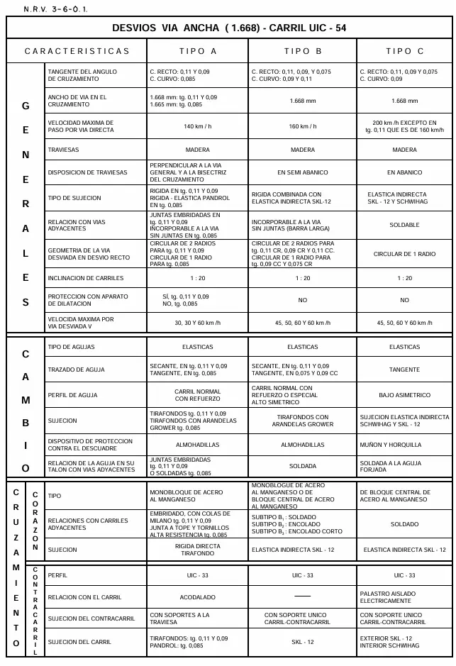
X.3.1. TYPE A TURNOUTS
Type A turnouts represent the previous generation of devices, which were installed extensively in the RENFE network until recently. Regarding future network expansions and modernizations, these turnouts should only be installed in sidings and shunting tracks of the entire Network, as well as in general tracks of the Secondary Network. They may exceptionally be used in circulation tracks of the Main Network if more modern types are unavailable, although it is highly preferable to use more advanced types in these locations. They are also valid for repairs and partial rehabilitations of existing devices of this type.
These devices allow maximum passage speeds on through route of 140 km/h and 30 km/h on the diverging route. An important technical limitation is that their frogs are not suitable for direct welding to the Long Welded Rail (LWR/CWR), making it necessary to intercalate special expansion devices. Exceptionally, the turnout model DS-A-54-500-0.085-CC does admit 60 km/h on the diverging route and can be integrated directly into the long rail without intermediate expansion devices.
They are manufactured for tracks with 45 prime or UIC 54 rail models, being seated on conventional wooden sleepers.
X.3.2. TYPE B TURNOUTS
Type B turnouts constitute an intermediate generation that allows passage on through route at maximum speeds of 160 km/h in models B1 and B2, and 140 km/h in model B3, while on diverging route they allow speeds of 30, 45, and 60 km/h depending on the specific model.
An important advantage is that they do not require the installation of special expansion devices, allowing safer direct integration with the long welded rail. They are manufactured for tracks with UIC 54 model rail and are subdivided into three varieties:
- Type B₁: Turnouts with frog welded to connection coupons of 2.40 m length, these coupons being aluminothermically weldable to the continuous long rail.
- Type B₂: (In extinction phase) Turnouts with frog bolted and glued to connection coupons of 2.40 m that can be aluminothermically welded to the long rail.
- Type B₃: Turnouts with frog that can be bolted and glued directly to the long rail without intermediate coupons. Their total length is reduced, being comparable to that of their Type A equivalents.
With the overcoming of technical manufacturing problems of Type B₁, production of Type B₂ has practically ceased. They are seated on wooden sleepers.
X.3.3. TYPE C TURNOUTS
Type C turnouts represent a more modern generation and allow passage on through route at maximum speeds of 200 km/h, while on diverging route they allow speeds of 45, 50, and 60 km/h depending on the specific model. Exceptionally, the model DS-C-54-250-0.11-CR only admits 160 km/h on through route.
They are manufactured for tracks with both UIC 54 and UIC 60 rails, thus allowing adaptation to different rail standards. Currently, they are seated on wooden sleepers, although in future modernizations migration towards concrete sleepers is anticipated.
X.3.4. TYPE V TURNOUTS
Type V turnouts constitute a specialized category that allows passage on through route at maximum speeds of 200 km/h, while on diverging route they allow speeds of 100 km/h, with prototypes in development aspiring to reach 130 km/h.
They are manufactured only for tracks with UIC 60 model rail, limiting their application to the most modern lines. Currently, they are seated on wooden sleepers, although their evolution towards concrete supports is anticipated.
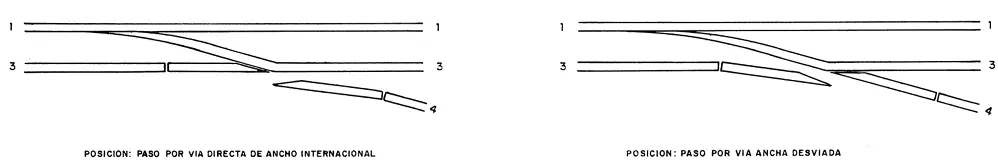
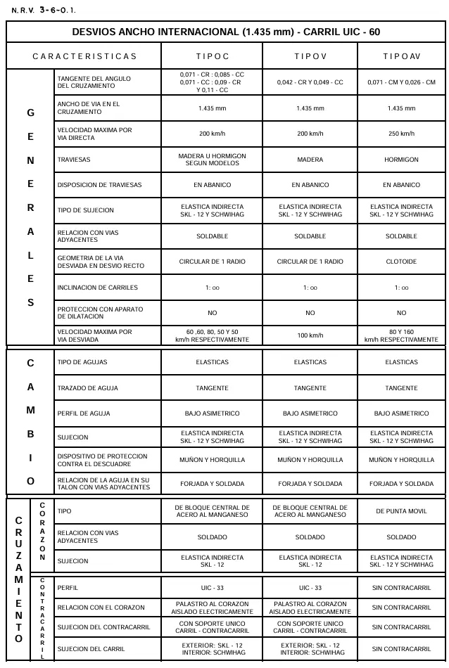
X.4. INTERNATIONAL GAUGE
X.4.1. TYPE A TURNOUTS
Type A turnouts for international gauge take advantage of components (switches and frogs) of Type A wide gauge turnouts, adapting them to the 1.435 m international gauge.
Maximum permitted speeds are 140 km/h on through route and 30 km/h on diverging route. They are manufactured for tracks with UIC 54 rail with the following tangent options:
- Tangent 0.09 using half-switches and crossing from its wide gauge counterpart
- Tangent 0.11 with half-switches and crossing from its wide gauge counterpart
- Tangent 0.11 with half-switches from the 54 kg wide gauge turnout with tangent 0.13, combined with crossing of tangent 0.11
They are not weldable to the long rail, therefore requiring the installation of special expansion devices. They are seated on wooden sleepers.
X.4.2. TYPE B TURNOUTS
They also take advantage of components from wide gauge turnouts (Type B₁), adapting them to international gauge.
They are manufactured for tracks with UIC 54 model rail, allowing speeds of 160 km/h on through route and between 40 and 60 km/h on diverging route.
Available models present the same tangents and similar characteristics to their wide gauge counterparts. They are weldable to the long rail, not requiring expansion devices. They are seated on wooden sleepers.
X.4.3. TYPE C TURNOUTS
For this category, four models have been foreseen taking advantage of components from wide gauge turnouts (Type C), in addition to 10 additional models developed specifically with UIC 54 and UIC 60 rails.
They allow speeds of 200 km/h on through route and between 45 and 80 km/h on diverging route. Exceptionally, model DSI-C-54-320-0.11-CC only admits 160 km/h on through route.
They are weldable to the long rail without requiring expansion devices. Currently, they are seated on wooden sleepers, with the exception of model DSI-C-60-760-0.071-CC which is seated on concrete sleepers.
X.4.4. TYPE V TURNOUTS
Two different models have been developed with UIC 60 rail, with tangents of 0.042 CR and 0.052 CC (the latter being still in development phase).
They allow speeds of 200 km/h on through route and 100 km/h on diverging route. They are weldable to the long rail without intermediate expansion devices. Currently, they are seated on wooden sleepers.
X.4.5. AV TURNOUTS (HIGH SPEED)
There are 2 different models with UIC 60 rail, both equipped with swing nose crossings (movable point frogs) according to the most modern technology.
They allow speeds exceeding 200 km/h on through route and 80 and 160 km/h on diverging route respectively. They are weldable to the long rail without requiring expansion devices. They are seated on concrete sleepers.
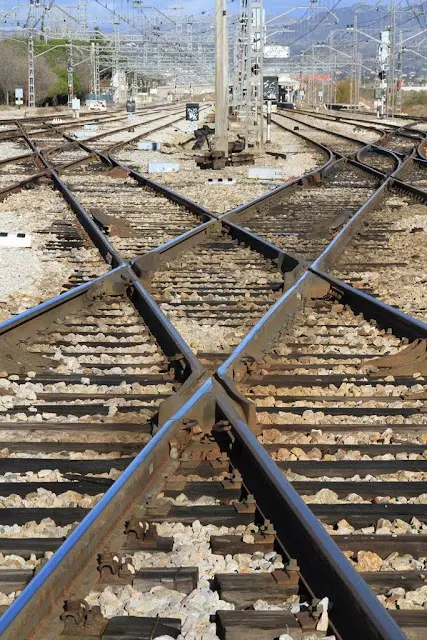
Chapter XI Diamond crossings (travesías)
Diamond crossings are complex track devices that allow the crossing of two railway itineraries. These devices can be classified according to various functional and geometric criteria detailed below:
\[\text { Diamond Crossings }\left\{\begin{array}{c} \text { Simple }\left\{\begin{array}{l} \text { Right Angled (Square) } \\ \text { Oblique (Angled) } \\ \text { Curved } \end{array}\right. \\ \text { Slips (De unión) }\left\{\begin{array}{l} \text { Single Slips } \\ \text { Double Slips } \end{array}\right. \end{array}\right.\]Simple Square Crossings:
These devices facilitate the intersection of two tracks crossing at right angles, being capable of operating with tracks of equal or different gauge. Their internal structure consists of multiple elements:
- Four crossings arranged at right angles to one another
- Four check rails strategically located to guide the rolling stock
- An inner check rail of closed contour providing additional protection
- Other minor connection and support pieces
These devices are typically manufactured as single monoblock pieces.
XI.1. Simple Oblique Crossings:
Oblique crossings allow the crossing of two tracks with an angle different from a right angle, permitting the intersection of tracks of equal or different gauge. Their structural configuration is more complex than the rectangular one, including:
- Two acute crossings (common crossings)
- Two obtuse crossings that provide additional guidance
- Connection rails and other specialized pieces
Typically manufactured as single monoblock pieces.
XI.2. Simple Curved Crossings:
These crossings provide solutions for cases where geometry is more complex: they allow crossing between a straight track and another in a curve, or between two curved tracks. Their geometric structure requires specialized design.
They have constructive components identical to those described for oblique crossings, adapted to the specific curved geometry of the application.
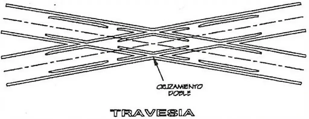
Double Slip Crossings (Travesías de unión doble):
Double slip crossings constitute a specialized configuration that combines elements of an oblique crossing with components of simple turnouts. This integrated design allows rolling stock circulation in four different directions, providing functionality equivalent to two ordinary turnouts facing each other, but occupying approximately half the longitudinal space.
This space saving is especially valuable in land restrictions typical of service and shunting zones in stations. However, speeds exceeding 70 km/h are not advised on these crossings.
Due to these speed limitations, their use is restricted mainly to service and shunting zones of stations.
They are formed by the following components:
- Two obtuse crossings
- Two common crossings
- Four pairs of switch blades (switches)
- Connection rails and other specialized minor pieces
Single Slip Crossings (Travesías de unión simples):
Single slip crossings allow rolling stock circulation in three different directions, providing less versatility than double slips but also occupying less space.
The use of this type of crossing, like double slips, is generally discouraged by railway administrations, except in those specific cases where the lack of available space economically compensates for the high expenses derived from conservation and repair that these devices require.
Chapter XII Other track devices
There exists a series of other devices that allow passage and maneuver between tracks:
- Crossover loop.
- Turntables and transfer tables.
- Wye tracks (Triangles).
XII.1. CROSSOVERS
Crossovers are connecting devices that join two adjacent tracks, allowing the passage of rolling stock from one to another. Their total length depends on the specific type of crossing employed in their construction.
Normal Crossover: allows rolling stock to pass from one track to another in a single direction of circulation, providing a unidirectional connection between parallel tracks.
Scissors Crossover (Escape cruzado): a more versatile configuration that allows passage in both directions, facilitating more complex maneuvers between adjacent lines.
XII.2. TURNTABLES
Turntables constitute rotary mechanical devices that have been extensively used in locomotive depots and specialized shunting zones. Their function is to orient the rolling stock towards the desired direction and subsequently direct it onto a selected destination track. Typically, access tracks are arranged in a radial configuration around the appliance, like the spokes of a wheel.
From an operational perspective, these devices present the advantage of occupying a relatively reduced space. However, they have the significant limitation that they can only change tracks for one vehicle at a time, limiting their shunting capacity.
It is important to note that, with the introduction of modern locomotives and units with double driving cabs (allowing driving in both directions without turn-around), these devices are increasingly less used in new installations.
XII.3. WYE TRACKS (TRIANGLES)
This device occupies more space than turntables, allowing the \(\mathbf{1 8 0}^{\boldsymbol{\circ}}\) turn of an entire train. Wye Tracks \(\left\{\begin{array}{c}\text { Symmetrical }\left\{\begin{array}{l}\text { with straight main track } \\ \text { with curved main track }\end{array}\right. \\ \text { Asymmetrical }\left\{\begin{array}{l}\text { with straight main track } \\ \text { with curved main track }\end{array}\right.\end{array}\right.\) To establish these devices, a study must be done relating occupied space and daily capacity.
Chapter XIII Other devices
Although the railway installations described below do not strictly respond to the formal technical definition of track appliance, they are usually considered an integral part of connection and shunting infrastructure in professional practice.
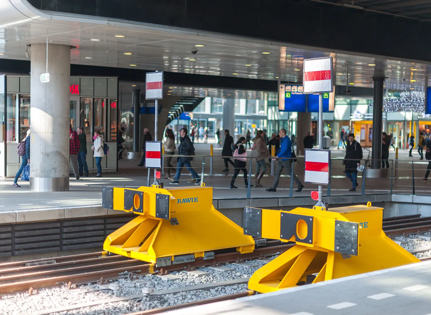
XIII.1. BUFFER STOPS (TOPERAS)
Buffer stops are fixed safety devices, strategically installed at the final ends of terminal tracks. Their essential function is to stop the movement of rolling stock as a final safety measure, in case for some reason the normal braking systems of the convoy did not act correctly.
Two main categories are distinguished according to their operation mode:
-
Rigid Buffer Stops: used by the RENFE administration, manufactured in concrete or metal, acting by physical obstacle to movement.
-
Deformable (Energy Absorbing) Buffer Stops: based on friction shoe systems, which transform the kinetic energy of the train into heat through controlled friction.
Energy Absorption Railway Installation (IFAE):
This special system represents a more sophisticated solution for kinetic energy absorption. Its operation is based on transforming the kinetic energy of the train into heat in a controlled manner. These systems have the capacity to stop convoys of 1200 tons weight when circulating at speeds of 10 km/h.
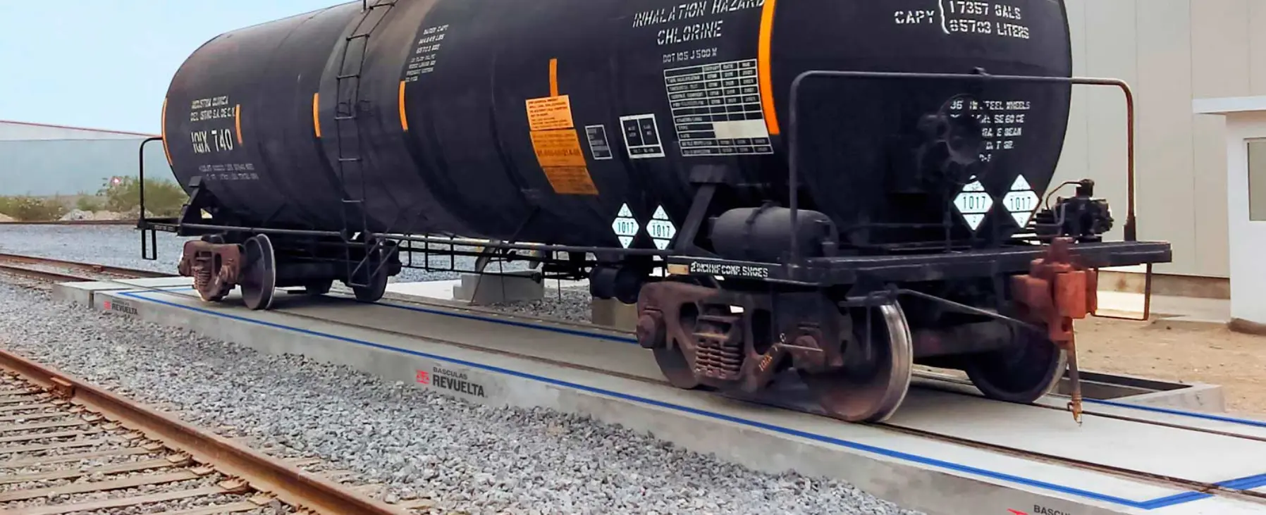
XIII.2. WEIGHBRIDGES (BASCULAS)
Railway weighbridges are specialized installations installed on dedicated tracks (not on general traffic tracks), designed specifically to perform control and verification of the weight of rolling stock and its cargo. They have special importance in freight stations, specialized sidings, and port zones where weight control is critical for safety and correct tarification.
XIII.3. SCOTCH BLOCKS / WHEEL CHOCKS
Scotch blocks are small mechanical devices permanently anchored to the rail, typically installed in railway stations. They are placed strategically at the access of secondary tracks to the main line, with the purpose of preventing rolling stock parked on secondary tracks from moving towards the main line without control.
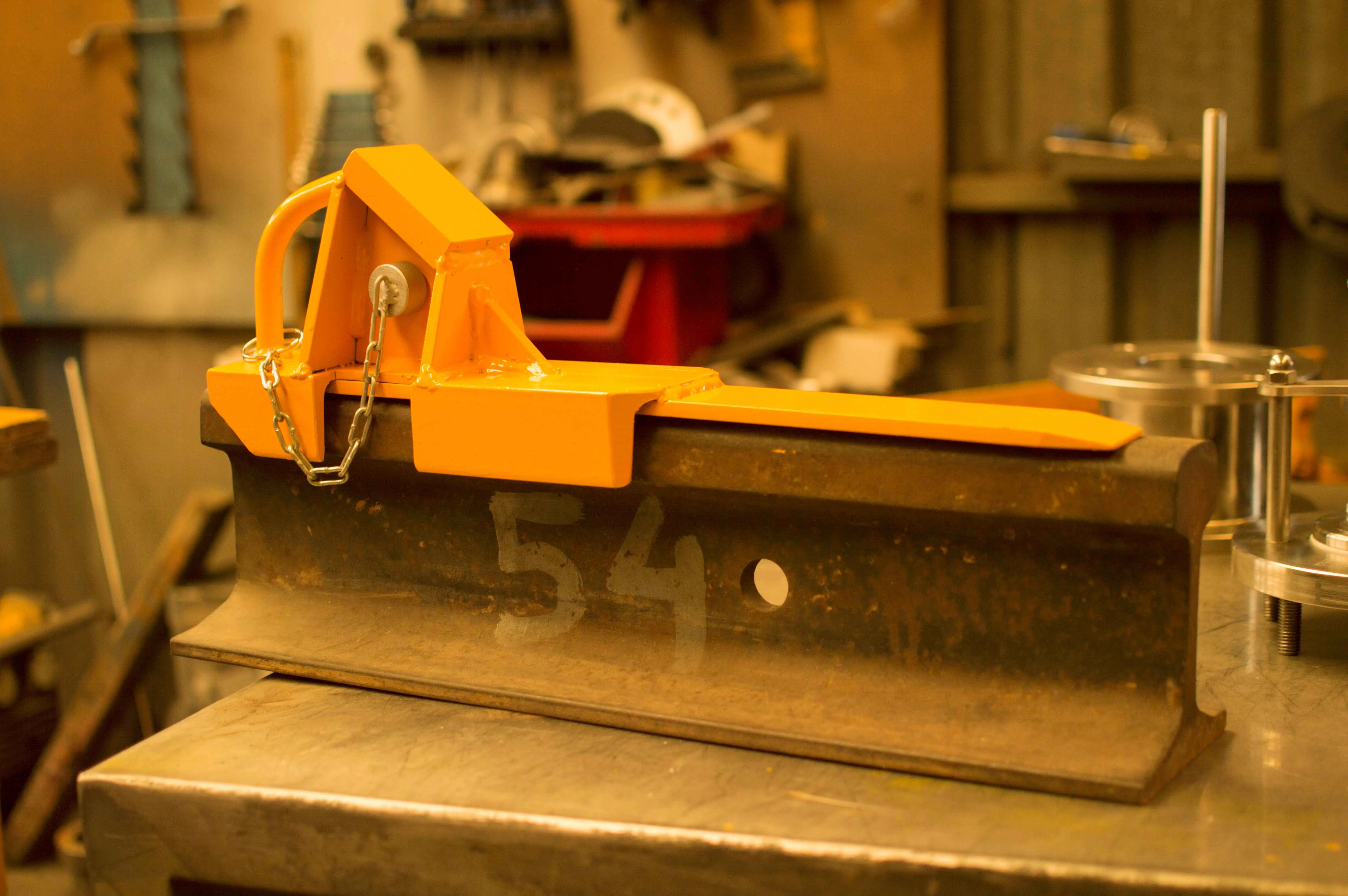
XIII.4. DERAILERS (AGUJA DESCARRILADORA)
A derailer (or derail) is used in railway systems as a safety mechanism to prevent an unauthorized or out-of-control railway vehicle from invading a track where it could cause a major accident. The derailer is used for:
- Protection of main lines: Placed on secondary tracks, sidings, or shunting zones to prevent a poorly braked train or wagon from accidentally entering a main line where trains circulate at high speed.
- Protection of workers: When there is personnel working on a track, the derailer prevents an unauthorized vehicle from reaching the work zone.
- Control of parked rolling stock: In yards or stations, if a wagon remains poorly secured and begins to move, the derailer derails it in a controlled manner before it reaches dangerous zones.
- Prevention of collisions: If a train approaches a protected area without authorization (for example, a workshop, a depot, or an occupied track), the derailer acts as a last resort to avoid a collision.
Chapter XIV Representation of track devices on plans
XIV.1. GENERAL CONSIDERATIONS
The graphic representation of track devices on technical plans follows standardized conventions that allow clear and uniform communication between professionals. Simple straight turnouts are represented schematically according to RENFE regulation NRV 3-60.0, using the following representation conventions:
Elements of representation:
-
The through route (direct track): drawn by its longitudinal axis, representing the main trajectory of the turnout.
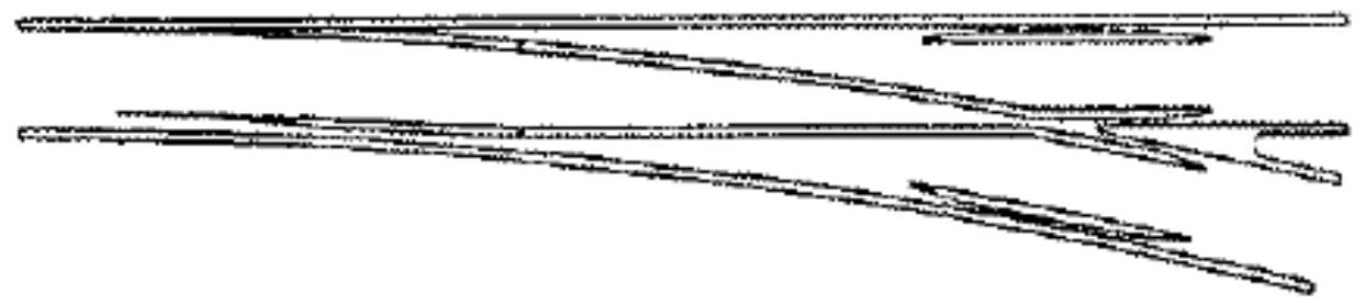
-
The diverging route: represented by means of the tangent of its axis at the end of the turnout. The point where this tangent of the diverging track intersects the axis of the direct track receives the name of Turnout Node (ND).
-
The Turnout Node: represented graphically by a small circle on the plan, marking the theoretical intersection of both tracks.
-
The start of the turnout (CD): is defined by the projection on the track axis of the joint of each stock rail, represented by a short vertical stroke.
-
The two ends of the turnout (FD): are obtained by projecting the final joints of the crossing onto the axes of the direct track and the diverging track.
-
The frog: represented by a small quadrilateral of equal contiguous sides, which schematizes the part of the frog comprised between the theoretical point and the heel of the frog.
Representation of curved turnouts:
In curved turnouts, both the direct and diverging tracks are represented by curved axes reflecting the real geometry of the appliance.
XIV.2. NOMENCLATURE
The nomenclature of track devices follows the technical standard RENFE NRV 3-6-0.0, which establishes an alphanumeric code containing all relevant technical information of the appliance. This code is structured as follows:
Structure of the nomenclature code:
- Type of track appliance:
- DS: Simple Turnout
- DSI: Simple Turnout of International Gauge
- DSIH: Simple Turnout of International Gauge seated on concrete sleepers
- Type of turnout:
- A: Old
- B: Good (subcategories B₁, B₂, B₃)
- C: Quality
- V: Speed
- AV: High Speed
- Rail class:
- 45: for 45 kg/m rail
- 54: for UIC 54 rail
- 60: for UIC 60 rail
-
Radius of the diverging track: its value expressed in meters
-
Tangent of the crossing angle: expressed in a single decimal figure
- Type of frog:
- CR: Straight Frog (Corazón Recto)
- CC: Curved Frog (Corazón Curvo)
- CM: Movable Point Frog (Corazón de punta Móvil)
- Deviation (direction):
- D: Deviation to the right (Derecha)
- I: Deviation to the left (Izquierda)
- S: Symmetrical
The direction of deviation is determined by observing the turnout from the start of the switch towards the crossing.
Example of interpretation:
As an example, consider the designation: DS-C-60-318-0.11-CR-D
This code corresponds to a simple turnout of RENFE gauge (broad gauge), seated on wooden sleepers, type C, with UIC 60 rail, radius of the diverging track of 318 meters, tangent of crossing angle 0.11 (ratio 1:9), straight geometry frog, and diverging track to the right.
Review Questions
How are track devices defined in railway engineering?
They are specialized devices that guarantee operational continuity at points where different trajectories connect, allowing the safe connection and crossing of tracks.
What are the two fundamental types of devices that make up track devices?
The Turnout (bifurcation of a track into two or more branches) and The Diamond Crossing (perpendicular/oblique crossing of two tracks).
What is trailing through a switch and what consequences does it have?
It is when a train forces the opening of an unprepared switch from the heel side. It causes deformation or rupture of the stretcher bars and forced separation of the blades.
What is the main function of check rails in the frog zone of a crossing?
To guarantee the guidance of the axle when traversing the frog gap, preventing derailment and protecting the point of the frog.
How is the gap problem solved in High Speed turnouts?
By using swing nose crossings (movable point frogs) or movable wing rails, which eliminate discontinuity in the running surface.
Bibliography
- Ferrocarriles. Class Notes. Jose Manuel Garcia Díaz de Villegas
- Desvíos Ferroviarios. Jose Manuel Garcia Díaz de Villegas - Miguel Rodriguez Bugarin
- Infraestructuras Ferroviarias. Andrés López Pita