Signalling Systems and Operational Methodologies in Railway Infrastructures
Table of Contents
Chapter I Introduction to Railway Safety
I.1. Safety
Definition of Safety
The absence of unacceptable risk of harm.
To adequately understand the protection mechanisms in railway infrastructures, it is fundamental to start from precise definitions of the basic concepts that structure safety analysis. In this context, we understand risk as the combination resulting from the probability of accidents or incidents occurring that are capable of generating harm, caused by specific dangerous factors, and the magnitude or severity of the damage they could cause.
Likewise, we term hazard (or danger) any circumstance that has the potential to originate an accident. It is also known as a risk source according to the UNE ISO 31000 standard. It is thus defined as that element which, whether in isolation or in interaction with other elements present in the system, possesses the inherent capacity to generate risk situations.
Since the origins of railway transport, the safety system for traffic has evolved based on four fundamental components that work in an integrated manner:
- The Regulatory Framework and Traffic Regulations
- Specialized Safety Installations
- Human Component
- Management of Uncontrolled Risks
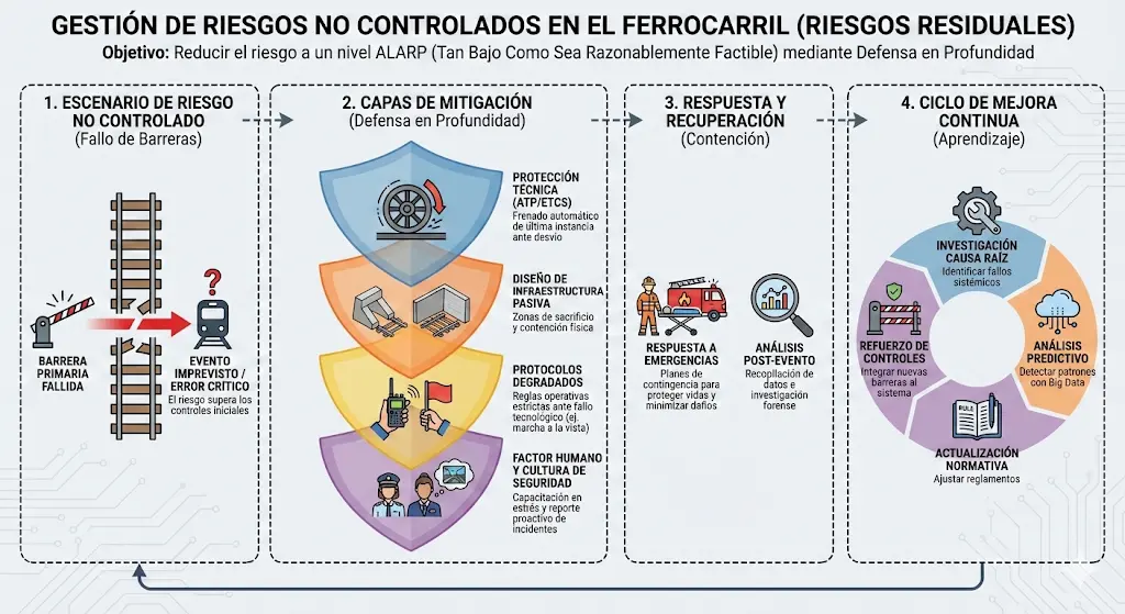
Concomitant with the progressive increase in operational speeds, it has been necessary to continuously improve and adapt existing installations with the purpose of significantly reducing hard-to-control risks and minimizing participation and the human factor in critical safety processes.
Generally, the degree of safety achieved in the railway transport systems of the European Union is situated at high levels. Although accidental events in railways occur with low frequency, when they effectively materialize they generate significant coverage and attention from the media.
This regulatory framework has been developed through several fundamental legislative instruments. Royal Decree 810/2007, of June 22, established the Regulation on traffic safety applicable to the Railway Network of General Interest, adapting Spanish legislation to that established in Directive 2004/49/EC regarding the safety of community railways and its subsequent modifications introduced by Directive 2004/51/EC.
Subsequently, EU Regulation 402/2013 on Common Safety Methodologies came to harmonize the procedures and technical approaches to carry out systematic risk assessment and to establish corresponding mitigation measures. This regulation is applicable whenever there is a variation in operating conditions or when new material is introduced that could involve the appearance of new risks either in the infrastructure or in operational services. Finally, Royal Decree 664/2015, of July 17, approved the Railway Traffic Regulation, thus completing the normative framework.
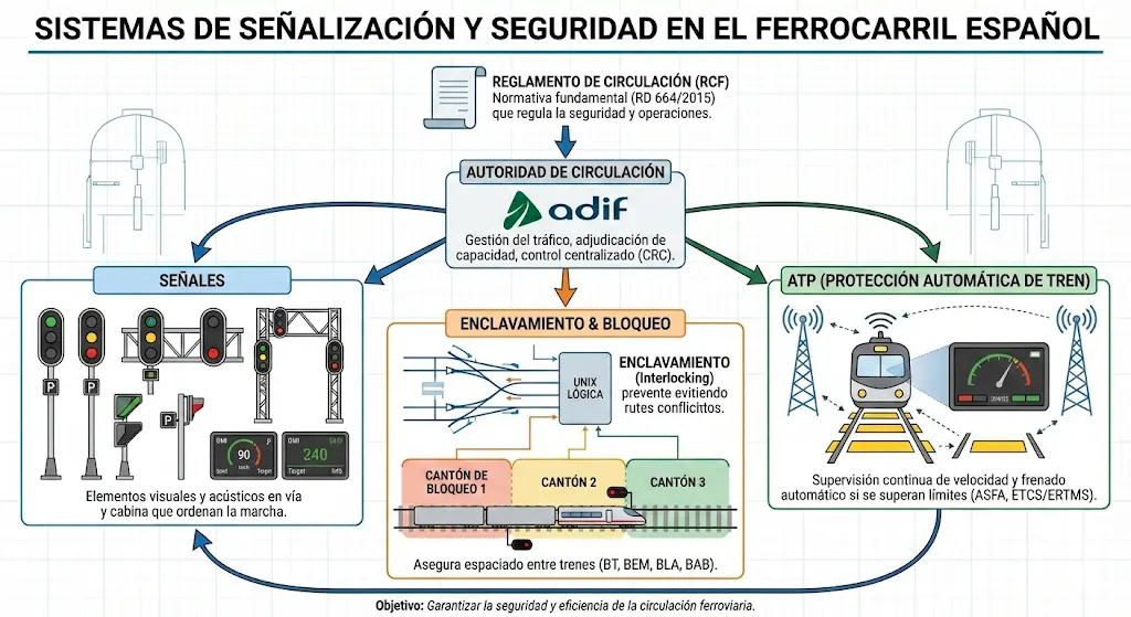
In operational practice, to guarantee safe circulation in the railway network, it is essential to adequately equip the routes with an organized set of signals that communicate to the train driver detailed information about potential obstacles, anomalies on the route, as well as speed limitations and track infrastructures available in the itinerary to be traveled.
Before authorizing any movement of a train, it is absolutely necessary to fix in a controlled manner the configuration of the track apparatus (switches) and ensure that the corresponding signals provide adequate protection. In this way, a relationship of dependence and interdependence is established between the position of the actuation devices, the protection barriers, and the signaling systems, a concept known as interlocking.
In addition to signaling systems, the infrastructure requires the installation of specialized blocking equipment that functions between consecutive stations and authorizes the safe circulation of the train on the routes between them.
There are also surveillance and supervision systems responsible for verifying compliance with signaling instructions. These systems are grouped under the denomination ATP (“Automatic Train Protection”).
In parallel, additional systems known as ATO (“Automatic Train Operation”) have been developed that enable completely automatic driving of trains. However, all these automatic operation systems are always supervised and controlled by ATP systems to ensure maximum safety.
Definitions of Key Terms in Railway Safety
| Term | Definition |
|---|---|
| Serious Accident | Any collision or derailment resulting in at least one fatality or 5 serious injuries, or damages valued at over 2 million euros. |
| Accident | Sudden unwanted event (collision, derailment, fire) that produces damage, even if minor. |
| Incident | Event that compromises safety but does not materialize in significant physical or material damage. |
I.2. Accident
We understand by accident that event which occurs suddenly, unforeseen or intentionally sought, or a concatenated series of events of these characteristics, which generates harmful consequences for people and property. Railway accidents can be classified into various categories according to their nature and origin:
- Collisions between trains
- Derailments
- Accidents at level crossings
- Injuries caused to persons by rolling stock in motion
- Fires in rolling stock
- Other types of incidents
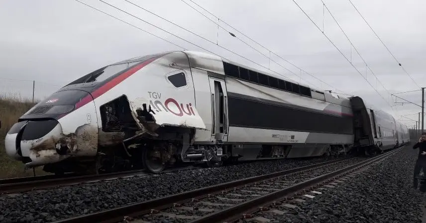 Infrastructure failure. Derailment of TGV Duplex in France due to a landslide on the Paris-Strasbourg high-speed line (2020)
 Earthquakes
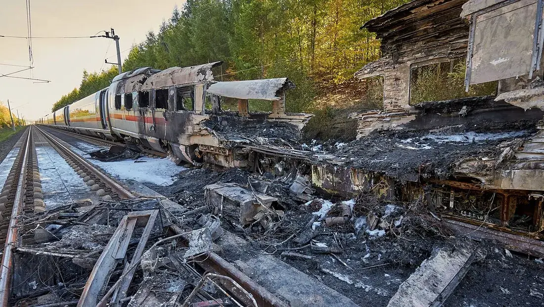 Fire of ICE 3 in Germany due to failure of onboard technical equipment. Cologne-Frankfurt high-speed line (2018)
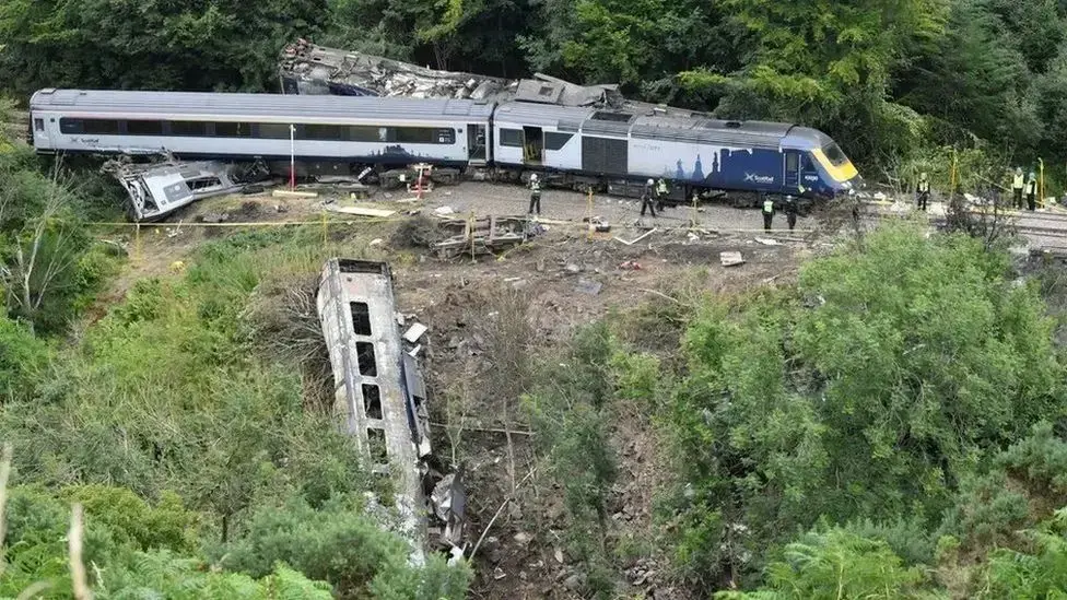 Derailment in Stonehaven (Carmont): The incident was caused by the collapse of a poorly designed drainage system, which proved incapable of channeling the flow of debris after the extreme rains of August 2020, displacing material onto the track.
Sabotage
In the most exceptional cases, accidents are not a consequence of technical or operational failures, but of deliberate and malicious actions. The following documentary image presents a real example of this type of circumstance:
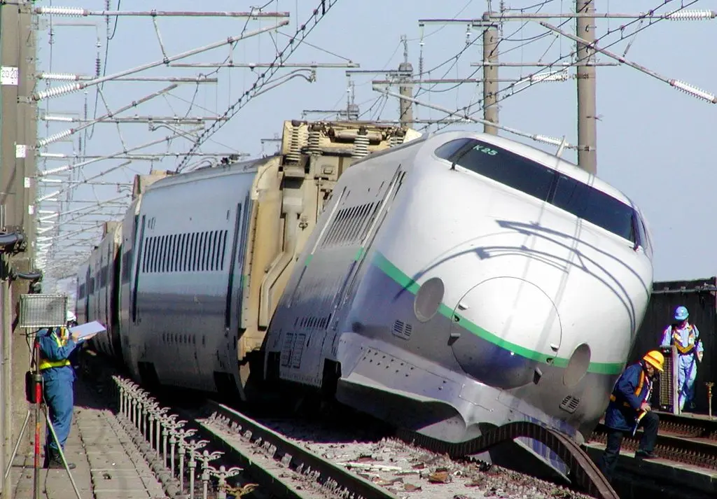
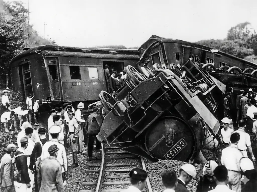 Matsukawa Derailment
The Matsukawa derailment occurred in the early hours of August 17, 1949, in Fukushima Prefecture, Japan, when a passenger train on the Tōhoku Main Line came off the tracks, resulting in the death of three crew members. Initial investigations revealed that the accident was a deliberate act of sabotage, as loosened bolts and nuts were found, as well as fastening spikes removed in a section of the track. This event was framed in a period of great social tension after World War II, being one of the three major railway incidents (along with those of Shimoyama and Mitaka) that marked the US occupation in Japan.
Following the incident, authorities arrested twenty people, mostly members of the railway union and the Japanese Communist Party, accusing them of political conspiracy. Although initially several were sentenced to death or long prison terms, the case became one of the country’s most famous miscarriages of justice; years of appeals and social mobilization revealed that confessions had been coerced and evidence manipulated by police. Finally, in 1963, the Supreme Court acquitted all the accused for lack of evidence, and the statute of limitations expired in 1970 without the real perpetrators being identified.
I.3. Serious Accident
A serious accident is defined as any event involving a collision or derailment of trains resulting in at least one fatality or more than five people with serious injuries, or causing substantial damage to rolling stock, infrastructure, or the environment. Likewise, other similar events that have an evident impact on railway safety regulations or safety management systems are considered serious accidents. For the purposes of this classification, “substantial damage” is understood as damage whose economic assessment, carried out immediately by the competent investigation body, reaches a minimum of 2 million euros.
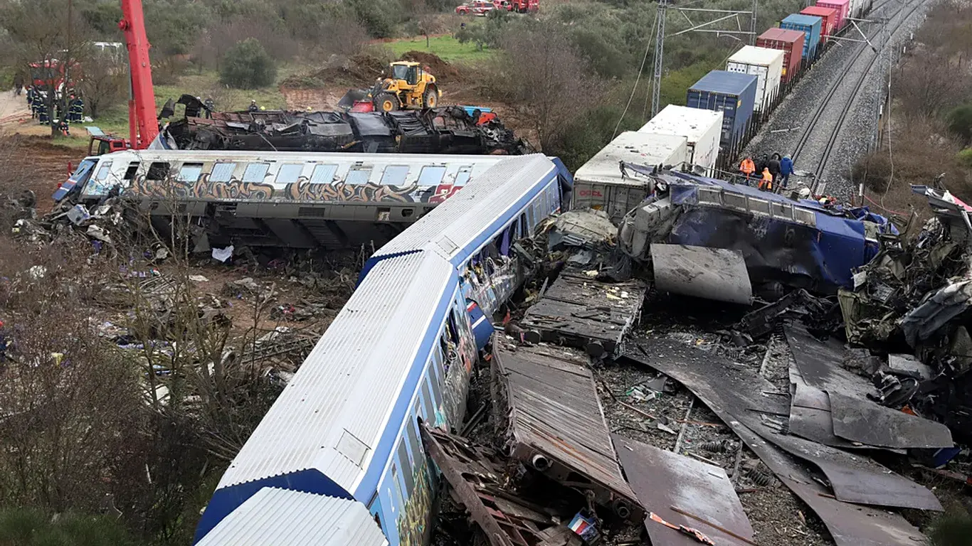 Human failure: Tempi Accident in Greece (2023)
Material failure (running gear)
I.4. Incident
We call an incident any event or anomalous situation, which although it does not constitute an accident or a serious accident in a formal sense, is related to the operation of trains and can significantly affect safety conditions and the safe operation of the system.
An incident is termed any event, other than an accident or a serious accident, that affects or may affect the safety of railway operations.
Unlike an accident, an incident does not usually entail serious personal injury or massive material damage immediately, but reveals a system failure that could have ended in tragedy.
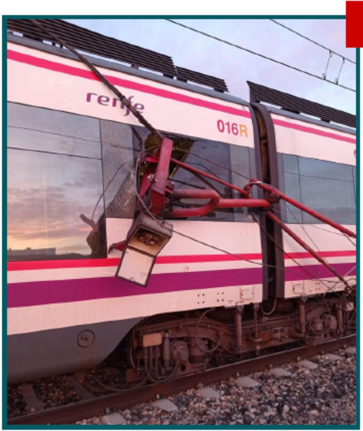 Pantograph detachment in UT 465, Madrid (2021)
I.5. Safety in Railways
Safety systems act mainly in the detection and prevention of technical failures in rolling stock, which constitute an important source of operational risk.
Comprehensive railway safety analysis must consider multiple dimensions of protection that go beyond traditional operational technical aspects:
- Operational Safety (Safety)
- Security against illicit acts (Security): Preventive security against malicious and vandal acts.
- Cybersecurity: includes protection against cyber threats and attacks on digital systems.
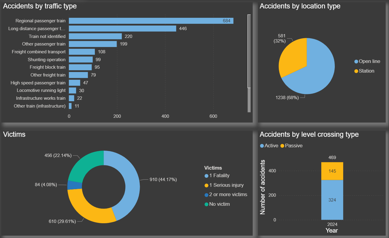
I.6 Analysis of Main Accident Causes (2024 data)
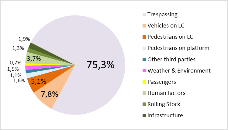
In accordance with the UIC Safety Report 2025, it is established that actors and third parties unrelated to direct operation are responsible for more than 90% of registered railway accidents (classified as external causes). The most frequently identified cause in these events is unauthorized access to railway infrastructure zones. In contrast, internal causes originate both in infrastructure administration and in train operating companies. Within this category of internal causes, the human factor and personnel errors constitute the most significant percentage of responsibility.
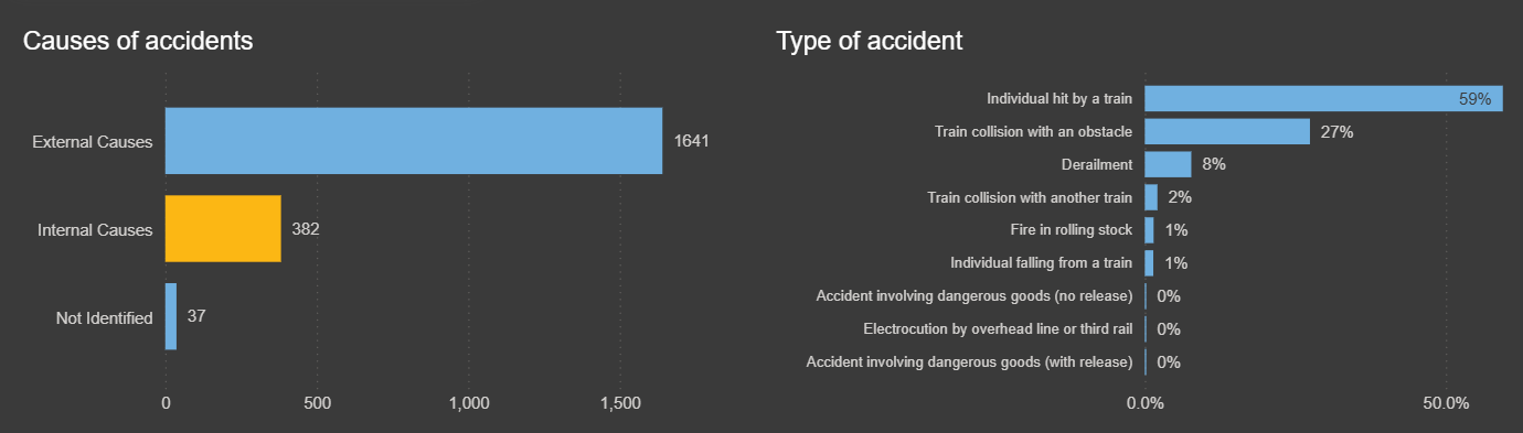
Statistically analyzing accident data registered in the year 2024, a clear distribution of accident modalities is observed. The vast majority of accidents occurred, representing 86% of the total, correspond to individual impacts or strikes caused when the train comes into contact with objects or people on the track. In second place, with 11% frequency, collisions of the train with various obstacles present on the route appear. Derailments constitute 8% of total accidents, whilst collisions between two or more moving trains represent only 2% of incidents.
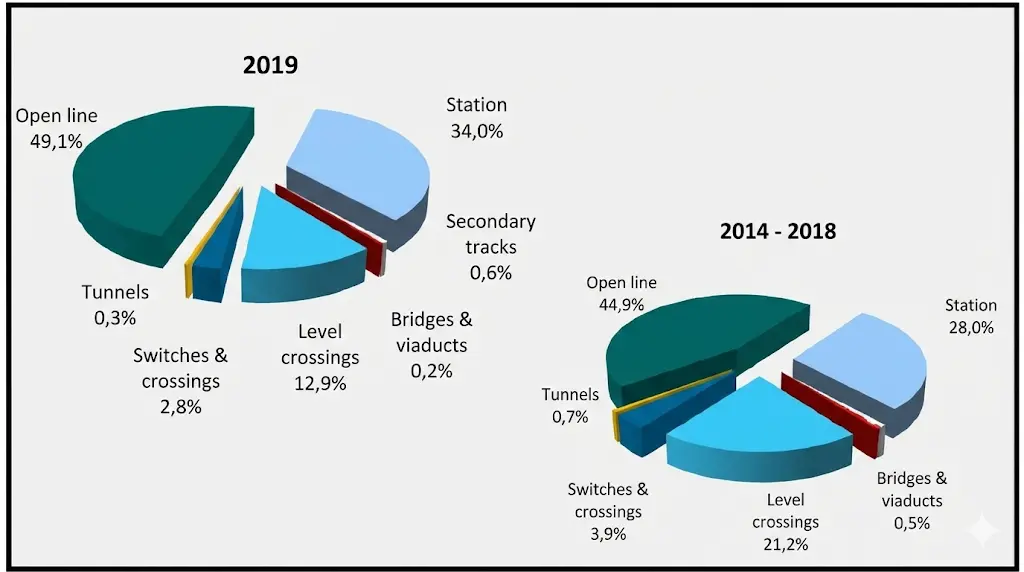
I.7. Location of accident occurrence (2024)
The geographical location where accidents occur in the railway network shows very defined patterns. Approximately half of all registered accidents happen in open track and exterior zones, far from specific infrastructures. The areas identified as subsequent critical points include operational stations and level crossings, which concentrate a significant proportion of incidents.
I.8. Process phases: Risk assessment
An essential stage in the development of any project or modification of a railway infrastructure is the rigorous execution of a risk assessment. This process allows identifying potential hazards and establishing proportionate preventive measures.
Risk Valuation
Explicit Risk Estimation
The matrix presented below constitutes a standard tool for classifying and evaluating identified risks. The axes represent the frequency of occurrence of the risk event (rows) and the potential severity of the consequences (columns). The combination of these two parameters produces a risk classification in categories of required response.
| I | II | III | IV | ||
|---|---|---|---|---|---|
| Insignificant (IN) | Marginal (MA) | Critical (CR) | Catastrophic (CA) | ||
| A | Frequent (FR) | Undesirable (INS) | Intolerable (INT) | Intolerable (INT) | Intolerable (INT) |
| B | Probable (PR) | Tolerable (TO) | Undesirable (INS) | Intolerable (INT) | Intolerable (INT) |
| C | Occasional (OC) | Tolerable (TO) | Undesirable (INS) | Undesirable (INS) | Intolerable (INT) |
| D | Remote (RE) | Negligible (DES) | Tolerable (TO) | Undesirable (INS) | Undesirable (INS) |
| E | Improbable (IMP) | Negligible (DES) | Negligible (DES) | Tolerable (TO) | Undesirable (INS) |
| F | Incredible (INC) | Negligible (DES) | Negligible (DES) | Negligible (DES) | Tolerable (TO) |
Chapter II Railway Signalling
This chapter will address the fundamental aspects that enable the safe and efficient operation of railway systems. Signalling constitutes one of the main pillars upon which all modern railway transport operability is sustained.
II.1. Objectives:
The function of railway signalling systems pursues the simultaneous fulfillment of two fundamental objectives:
- To provide the strictest conditions of traffic safety and train operation.
- To achieve the maximum possible efficiency of railway traffic, achieving operational regularity and ensuring sufficient transport capacity to respond to the demands of the corresponding line.
These two objectives present a relationship that is frequently antagonistic. Increasing safety measures tends to reduce transport capacity, and vice versa. System design must seek an optimal balance between both requirements.
II.2. Basic Functions
In order to achieve the objectives established above, railway signalling systems must perform an essential set of protection and traffic management functions:
- Prevent the occurrence of collisions or rear-end collisions between moving trains, as well as between a train and any object or person that has fallen onto the rails.
- Permit the departure and movement of trains only when a safe route has been previously established and when this route is compatible with all relevant operational restrictions in each particular circumstance.
- Prevent derailments caused by speeds that are inadequate or unauthorized for the trace characteristics.
- Authorize the movement of trains exclusively when the authority issuing the order is fully identified and legitimized.
- Guarantee that signal indications limit circulation speed such that the maximum permitted safety speed is never exceeded at any time.
- Establish and maintain in operation one or several modes of degraded operation and pre-established emergency plans that allow the continuous provision of essential services in situations of anomaly or failure.
Historical Evolution of Signalling Systems
During the early periods of railway transport development, operational lines were limited in number and circulation occurred at relatively low speeds. Under these initial conditions, the train driver did not have information on future operating conditions while making his journey, which frequently caused accidental situations.
To remedy this deficiency, at points considered dangerous or critical, dedicated people were located (signalmen and switchmen) who, through signals executed with hands or colored flags, communicated essential instructions to the train driver on how to proceed. The signalmen constituted the personnel in charge of coordinating movements, as they had information on the position of trains and authorized their circulation. The switchmen, for their part, were in charge of operating track apparatus (switches) and signals, as well as maintenance tasks for these devices.
With the passage of time and the substantial increase in railway traffic and operating speeds, these rudimentary measures proved clearly insufficient. It then became necessary to implement progressive technological reinforcements: first fixed mechanical signals were introduced, subsequently moving to electrical signal systems, and finally light signalling systems were developed, representing the basis of modern signalling.
Definition and Classification of Signals
We define a signal as the visual representation that communicates a warning, an operational instruction, or information about a system state that is essential for the safe management and control of railway traffic.
Signals can be classified according to their physical location and installation characteristics into three main categories:
- Fixed Signals: those that are found permanently or during established temporary periods, installed in specific locations on the track or in station facilities.
- Portable Signals: devices that can be used or deployed by operational personnel at any time and place according to operational needs.
- Train Signals: those physically installed on the rolling stock, typically at the head and tail of the convoy.
Regarding the spatial arrangement of fixed signals in the infrastructure, these are installed according to established norms that vary depending on the track typology. In case of single track, signals are placed to the right of the track in the direction of train travel. In double track systems with lateral running (the so-called left-hand traffic system), signals are installed to the left or above the rails. Finally, in bidirectional double track configurations (banalized track) that allow both directions of travel, signals are installed on the outside of the track so that they are visible to trains running in both directions.
II.3. Classification according to their CONTENT:
Railway signals can alternatively be classified according to the type of information they transmit:
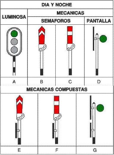
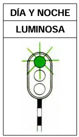
Fundamental Signals: are those that directly regulate the march and movement of trains. They use a standardized color code to transmit clear and unequivocal instructions to the train driver:
- Green → indicates free track, total authorization to proceed.
- Flashing Green → indicates conditional free track, with special restrictions.
- Yellow → constitutes a stop warning, indicating that a restrictive signal is approaching.
- Red → imperative stop order.
Indicator Signals: these signals provide complementary information on specific characteristics of the itinerary and operating conditions. Their function is to inform the train driver about:
- The track to be used (direct or diverging track)
- Entry and exit of operating stations
- Location of kilometric or hectometric posts for location reference
- Approximation to level crossings and other special situations
- Speed limitations applicable in the specific section
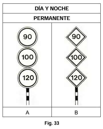
The top number affects Normal Type trains. The center number affects Type A trains. The bottom number affects Type B trains.
Chapter III Blocking System
The blocking system represents one of the fundamental mechanisms guaranteeing operational safety in railways. This concept is essential to understand how railway traffic is managed safely.
Definition and Fundamental Principles
Blocking is defined as the set of procedures and mechanisms that establish a relationship of dependence and coordination between two collateral (adjacent) stations with the purpose of allowing both to dispatch traffic (movement authorizations) from each one towards the other, through the specific controlled establishment of the exclusive reservation of a track section for a specific movement. This system ensures that at any given moment, only one train can occupy the track segment between stations.
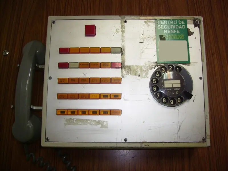
III.1. Telephone Blocking
Telephone blocking constitutes the most intuitive and conceptually accessible system of available blocking procedures. At the same time, it implies the lowest investment in specialized fixed installations, given that the operating block section covers the entire length of track between collateral stations that operate and have traffic personnel permanently present.
To establish a telephone block between two collateral stations, it is absolutely mandatory that there be an explicit agreement between the traffic managers of both stations. This agreement is typically made via telephone communication through dedicated railway operator lines, and must be duly documented in a register called telefonema (telephone message log). This document records the identification data of the train that is going to circulate, the expected departure time from the dispatching station, and the full names of the traffic agents who have intervened in the negotiation and agreement.
The telephone blocking system is the one that requires the greatest workload and personnel for its continuous operation. For this reason, currently it is not installed on any line as the main blocking system.
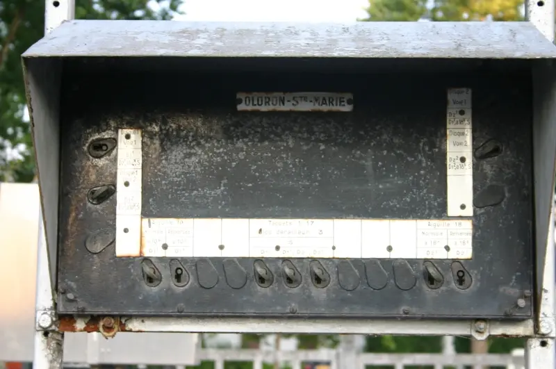
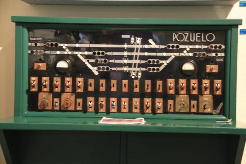
III.2. Manual Electric Blocking
In this system, the function of control and coordination of track blocking is performed by the traffic managers of each station using specialized electrical devices. This technology represents a significant advance over pure telephone blocking.
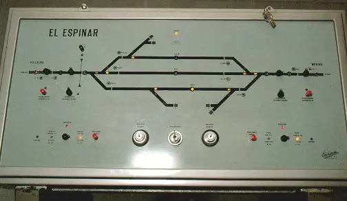
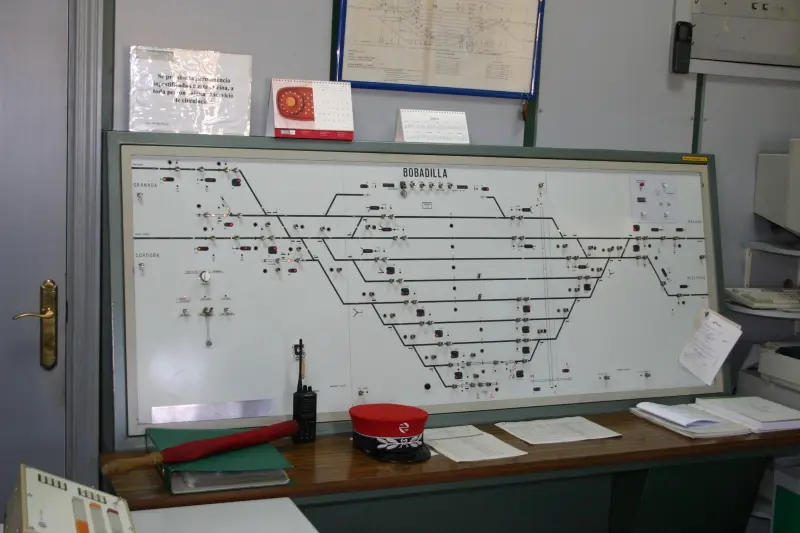
In each of the operating stations, the traffic manager has a centralized control panel. This panel contains a schematic and synoptic representation of the tracks that make up the station, also including approach and exit tracks towards adjacent stations. All elements and devices necessary to establish blocking in a controlled manner are integrated into the panel.
Although command actuation is manual (the operator must physically execute the action), electrical communication between the exit signals of collateral stations is automatic. This hybrid characteristic combines manual control with automatic information transmission.
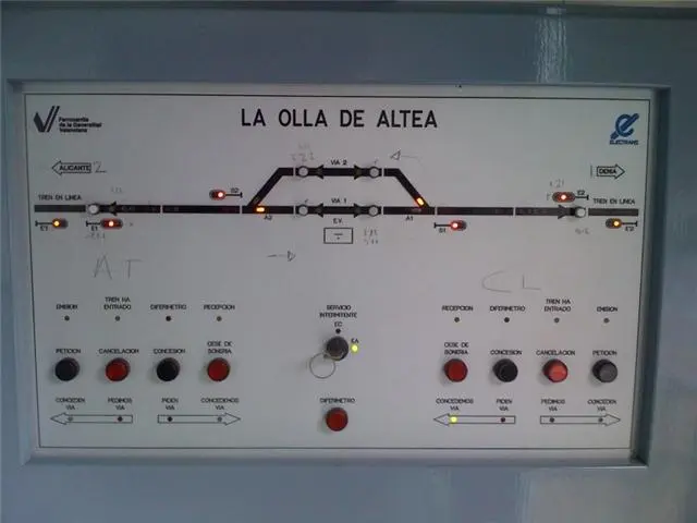
STATION
 Request and granting of track
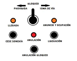
Taking of track
III.3. Automatic Blocking
The fundamental concept underlying automatic blocking is that the required safety distance between two trains traveling in the same direction must be sufficiently wide so that the train following the first can completely stop its movement within that separation space. This must be valid even in the most unfavorable scenario, where the train is traveling at maximum speed, inappropriately passes a stop signal, and simultaneously the vehicle’s emergency brake system is automatically activated.
This function of the signalling system provides a very high level of protection, making it practically impossible for a rear-end collision with the preceding train to occur, even in the event of a hypothetical driving system failure or inadequate driver conduct.
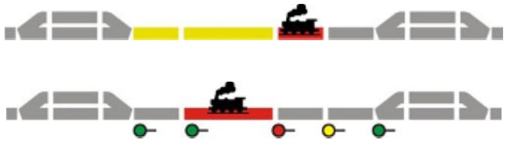
Signalling based on Block Sections (Cantons)
From this need for collision protection arises the traditional model of signalling based on light signals installed at the entries of block sections (cantons) and stations. A canton is defined as a specific section of railway infrastructure in which, under normal operating conditions, only one train can circulate at any given time, thus avoiding any possibility of collision between two trains.
In operating systems based on operation via fixed cantons, these segments are delimited and differentiated by signals, which provide the necessary movement authority for a train to access each canton. For a main signal to be in a green aspect (free track) and allow safe entry to the preceding canton, the following essential operating conditions must be simultaneously satisfied:
- The train that previously occupied the canton must have completely cleared that zone.
- The preceding train must have completely passed the overlap zone that exists after the next signal, ensuring an additional safety margin.
- The preceding train must be correctly protected from trains following it by means of a signal in stop aspect.
- The train requesting entry to the canton must be duly protected against opposing or conflicting movements.
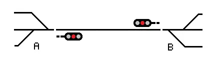 Single Canton
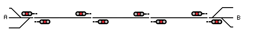 Multiple Cantons
Optimization of Traffic Capacity
An important relationship in the design of railway systems is the following: the greater the number of cantons in a given route, the greater the number of trains that can circulate simultaneously on that route, thus significantly increasing the line’s operational traffic capacity. Therefore, all optimization efforts must be directed towards reducing the individual length of cantons, with the essential condition that the distance between consecutive signals is adequate so that the train driver has sufficient time to completely stop the train within the same canton if receiving a stop indication.
The minimum permissible length of the canton is determined by two main factors:
- The distance required to brake the train, which is a function of the specific type of rolling stock employed, the braking system installed, and the maximum authorized speed of circulation on the route.
- The time necessary for the Central Command Post, once informed of the train’s current position, to verify and confirm this information, and finally act on the corresponding signal to change its aspect.
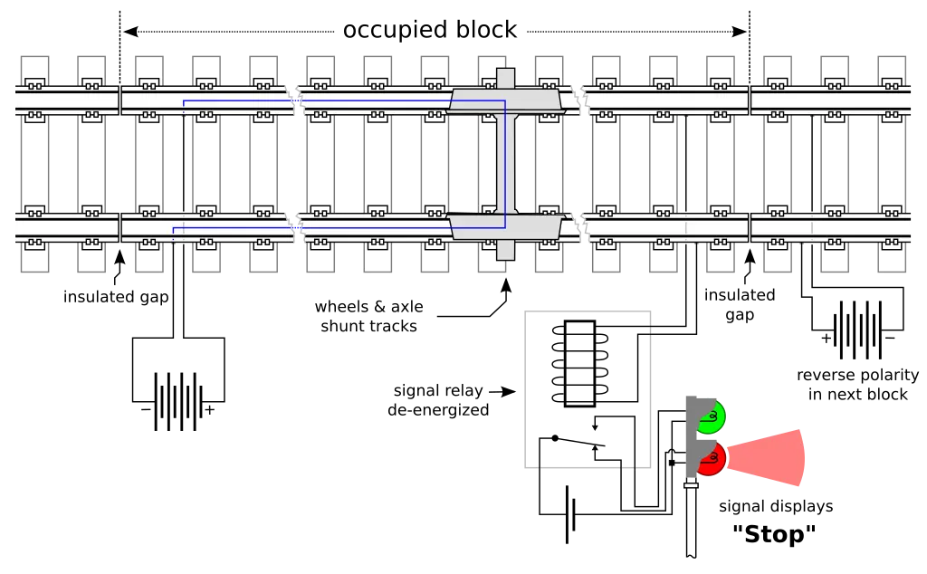
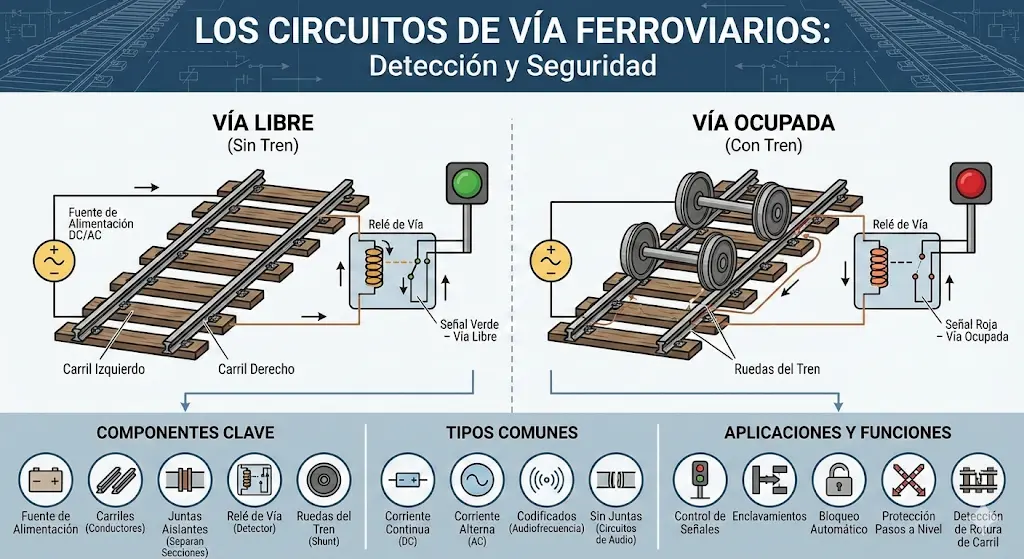
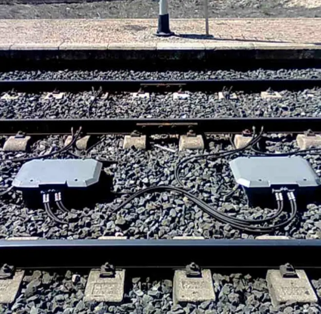
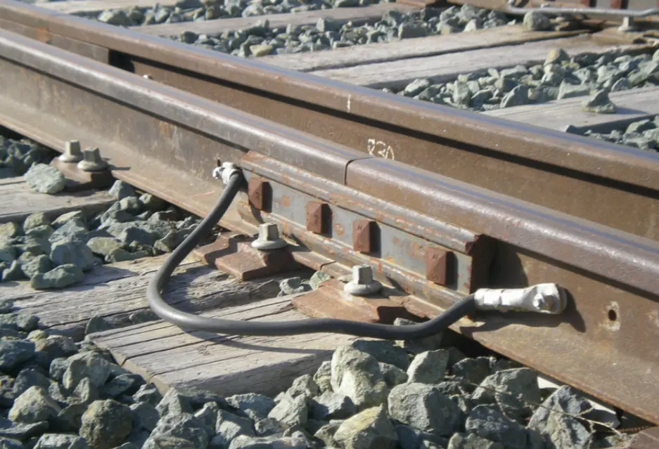
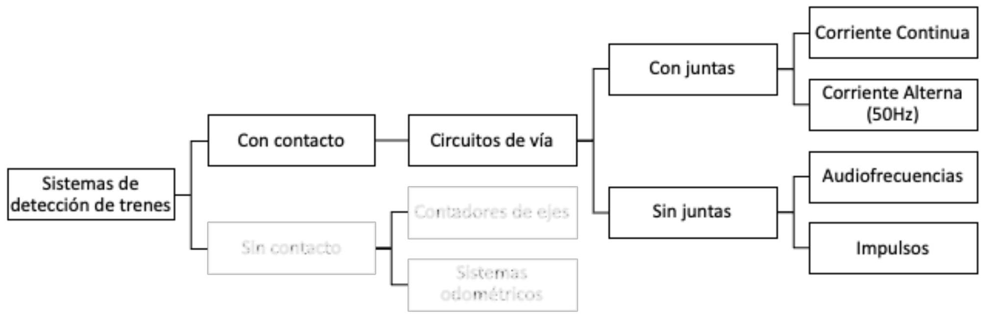
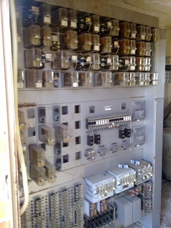
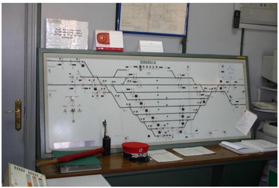
III.4. Track Circuits
Track circuits constitute essential components of track occupancy detection systems. A track circuit is defined as a specialized electrical circuit installed along a specific section of railway infrastructure. In this circuit, the rails themselves that make up the track are used as electrical conductors, forming an integral part of the circuit.
The fundamental purpose of a track circuit is to accurately detect the presence of railway vehicles on the section of track where it has been installed. This detection mechanism takes advantage of the fact that the metal axles of railway vehicles create a conductive shunt (a partial short-circuit) in the electrical circuit when wheels come into contact with the rails. This shunt causes measurable changes in the electrical parameters of the circuit that can be detected and processed by specialized control equipment.
 Control panel with track circuits
III.5. Automatic Blocking: BAU (Unidirectional)
Unidirectional Automatic Blocking (BAU) is one of the most widely used operating models in railways. In this system, blocking establishment is performed completely automatically without direct human intervention, using track circuits for occupancy detection and control systems to manage the release and occupation of cantons.
III.6. Automatic Blocking: BAB (Bidirectional)
Bidirectional Automatic Blocking (BAB) represents an extension of the automatic blocking concept allowing train circulation in both directions on the same track. The system must intelligently manage canton occupation in both directions, ensuring that no conflicts or incompatible opposing movements occur.
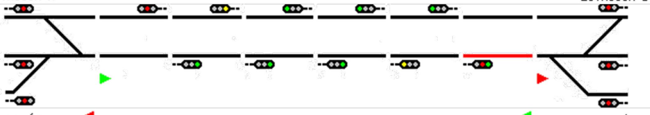
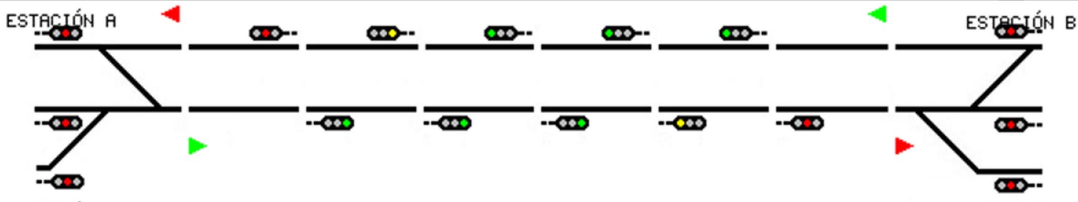
BAB Operational Phases:
When the train leaves station A, the system automatically marks occupation of the first canton. As the train advances through successive cantons, the system progressively releases abandoned cantons and blocks new occupied cantons, always maintaining a protection zone around the train.
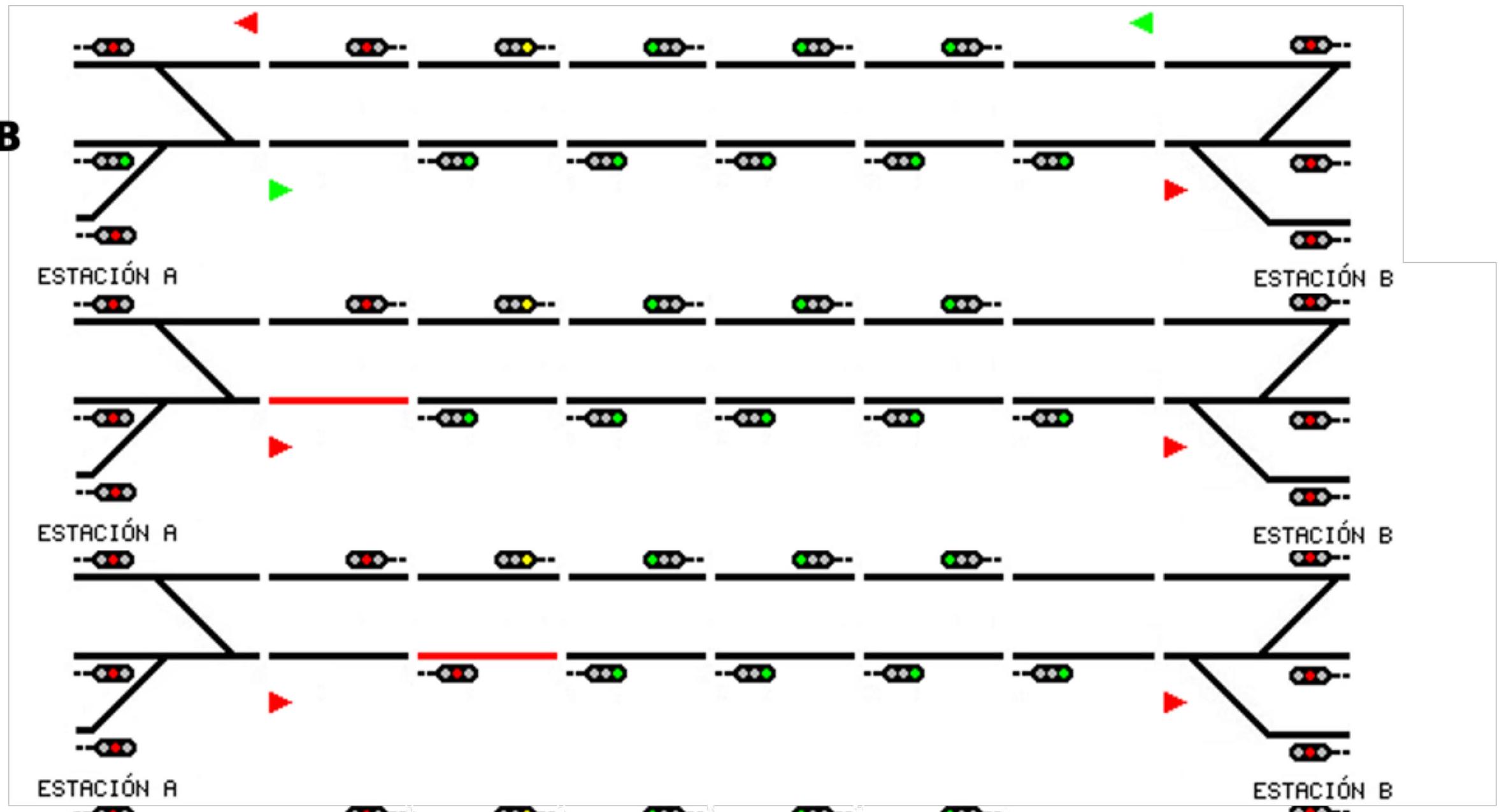
When the train fully enters station B, the system ends route blocking. Once the train has completely ceased movement inside station B, the route between A and B is completely unblocked, allowing a new train to be authorized to circulate from A to B or from B to another station.
III.7. Blocking and security systems of Metric Gauge Lines
In the specific case of Spanish metric gauge railway lines (1000 mm), the railway network has various blocking systems depending on the specific line and its level of modernization. This document presents an updated summary of the situation as of October 2022.
The following table summarizes blocking systems installed on different metric gauge lines and associated automatic train protection systems:
| Blocking System | Metric Gauge Lines (except line 116 Cotos-Cercedilla) |
|---|---|
| B.T. - Telephone Blocking | Applied in certain sections |
| B.A.U./B.A.D/B.A.B - Automatic Blocking + CTC | ASFA (analog) |
| B.A.U. - Unidirectional Automatic Blocking | - ASFA (digital) |
| B.E.M. - Manual Electric Blocking | STATIONS |
| Other procedures (regulated by operational instruction) | Special cases |
III.8. Blocking and security systems of Iberian and International Gauge Lines
Iberian gauge (1668 mm) and international gauge (1435 mm) lines that constitute the Railway Network of General Interest use more modern and sophisticated blocking and protection systems. These systems vary according to the level of modernization of each specific line, with some high-speed lines using state-of-the-art technologies such as ERTMS (European Rail Traffic Management System).
Chapter IV Interlockings
Interlocking systems constitute another fundamental pillar of railway operational safety. Their main function is to ensure that track apparatus, protection barriers, and signalling systems function in a coordinated and safe manner.
Definition and Principles of Interlocking
Interlocking is defined as the functional dependency relationship that must exist between the position of actuation devices (levers, buttons, etc.) of track apparatus, protection barriers, and their corresponding authorization signals. This dependency relationship ensures that these elements are actuated in a determined and specific order, with the object of guaranteeing safety for all authorized movements in a station.
The basic principles governing any interlocking system are as follows:
- It will not be possible to effect opening (change to permissive aspect) of a signal to authorize a movement before having placed all track apparatus comprising the route in the correct and safe corresponding position.
- It will not be possible to change the position of any track apparatus related to a movement route while the signal authorizing that route continues in open aspect.
- It will not be possible to perform opening of a signal to authorize a movement that is incompatible, conflicting, or dangerous with another movement that has already been previously authorized.
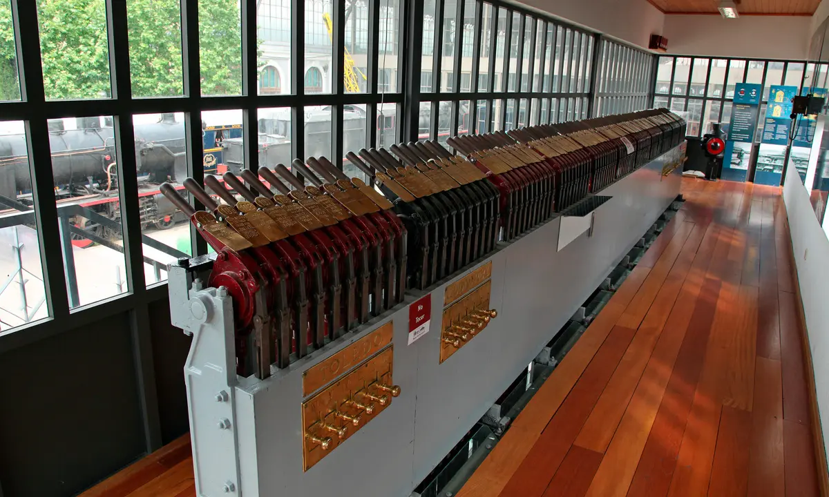
Mechanical Lever Concentration Interlocking
During the historical evolution of railway transport, with progressive development of railway infrastructure and exponential growth in station size, a major operational problem arose. As stations became more complex, the distance personnel had to travel to access diverse points where locks and actuation devices were installed became increasingly greater, generating significant operational inefficiencies.
To solve this problem, an innovative system was developed allowing all these actuation maneuvers to be performed remotely, from a centralized control post where all operational controls were concentrated. In this centralized system, functional dependency relationships (which are mechanical relationships) between maneuver levers of track apparatus and signals, and the actual physical position of these elements on the ground, were materialized through specialized mechanical transmission systems linking them.
IV.1. Electrical Interlockings
With technological advancement, interlocking systems were developed replacing purely mechanical mechanisms with electrically actuated systems. Electrical interlockings are advanced control posts using electrical circuits and devices to perform remote actuations of track apparatus. In this type of system, traditional mechanical signals are transformed into electrical signals controlled by relays, and track apparatus actuations are replaced by specialized electric motors performing switch change movements or other devices.
The central apparatus of an electrical interlocking is typically constituted by the following elements:
- Interlocking Table: where operational controls are located and station configuration is schematically represented.
- Relay Room: space where all specialized relay circuits executing logical interlocking functions are concentrated.
Main advantages of electrical systems regarding purely mechanical ones include:
- Considerable increase in speed of order transmission and safety check execution.
- Absence of physical limitations of distance or alignment between components.
- Notable streamlining in establishing authorized movement routes.
IV.2. Electronic Interlockings
Most recent technological evolution has led to development of completely electronic and computerized interlocking systems. The most representative system is CTC (Centralized Traffic Control), allowing management and governance from a single centralized command post (or central interlocking) of all traffic in a territorial zone or one or several complete railway lines. This system functions through continuous and automated information exchange between track apparatus installed in infrastructure, moving trains, and central interlocking system.
Elements necessary for CTC implementation:
- Electrical interlockings installed in each operating station conforming controlled zone.
- Automatic blocking systems between stations.
- A specialized data communications system linking Central Command Post with remaining peripheral system elements, allowing bidirectional information flow.
Chapter V Automatic Train Protection (ATP)
Automatic Train Protection (ATP) systems represent the most advanced evolution in railway safety. These systems continuously supervise compliance with signalling instructions and are capable of intervening automatically on train braking systems to prevent dangerous situations.
The following chapters will address main ATP systems in operation in Spanish and European infrastructures, including technical characteristics, functionalities, and implementation levels.
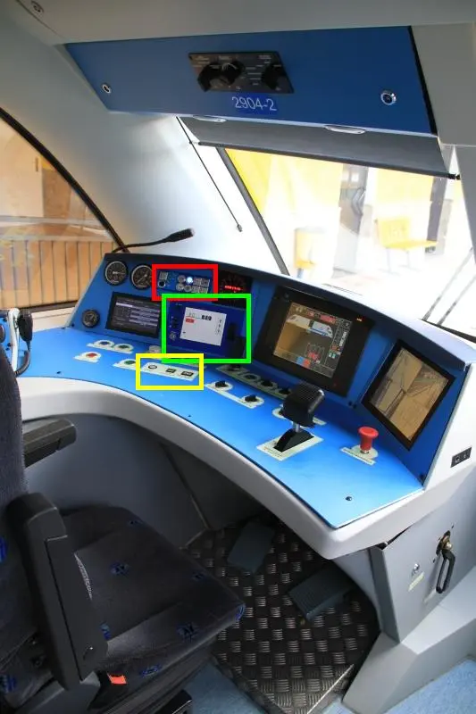
V.1. ASFA
ASFA (acronym meaning “Announcement of Signals and Automatic Braking”) constitutes the cab signalling and automatic train protection system most widely implemented on lines operated by RENFE (including conventional network), FEVE (Narrow Gauge Railways), and also on high-speed network (AVE). For the driver, ASFA system acts as a permanent reminder of current route signalling conditions, and forces him to actively respond to all restrictive indications appearing.
The system relies on specialized beacon technology located between rails, reproducing visual indication of each fixed signal. The first beacon (called advance beacon) is positioned approximately 300 meters before each signal, providing pre-warning to driver. The second beacon (signal beacon) is installed practically at same vertical location of signal (approximately 5-7 meters), transmitting definitive signal aspect information.
ASFA System Components:
The system is composed of two main functional sets:
- Track-side equipment: specialized inductive beacons and signal connection and conversion cabinets.
- On-board equipment: inductive signal detector or sensor, computerized control cabinet, and visual indicator panel. This equipment is functionally connected with train braking systems, tachograph, safety event recorder, and other onboard systems.
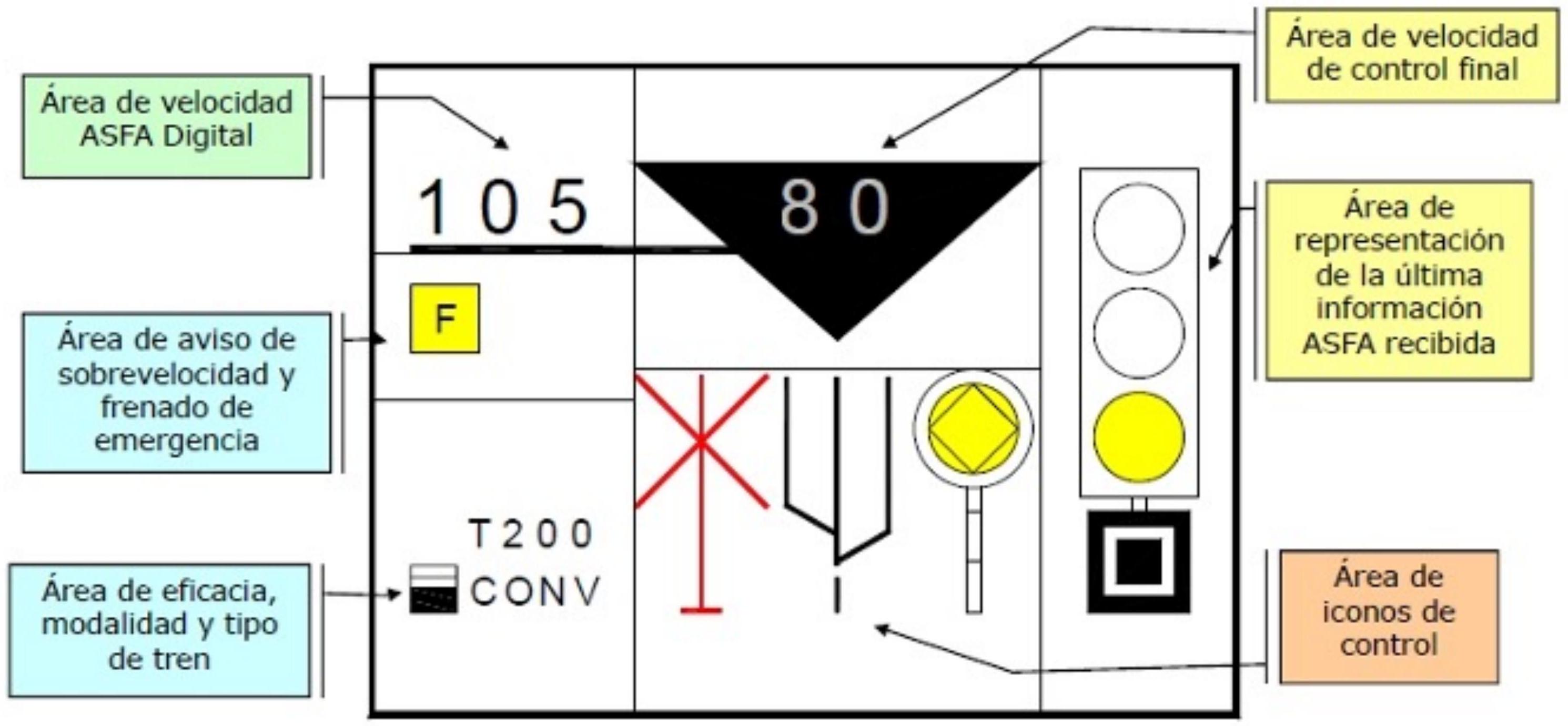
V.2. ASFA Digital
Technological evolution has allowed development of an improved version of ASFA system, called ASFA Digital, incorporating advanced information processing capabilities. This modernized system uses digital communications instead of analog ones, significantly improving accuracy, data transmission speed, and system supervision capacity.
ATP Systems: ASFA
Automatic train protection can be implemented via diverse technical approaches, each with specific operating characteristics:
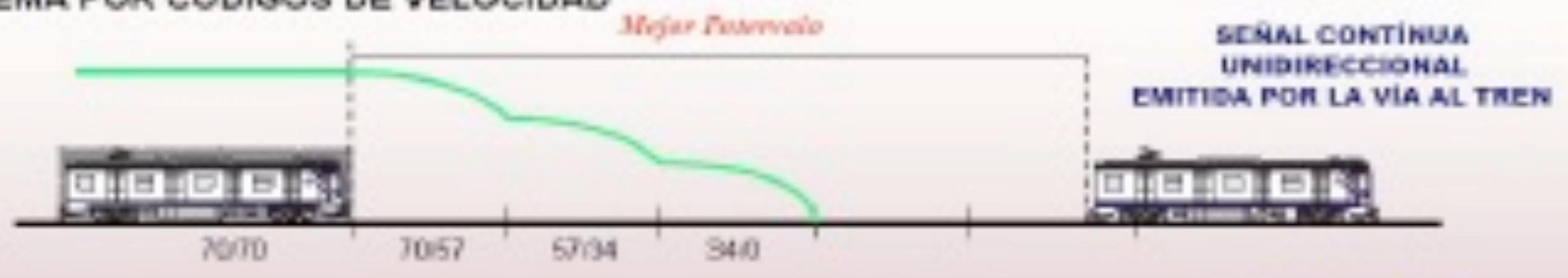
Speed Code System
This approach is based on transmission of codes specifying a maximum permitted speed in each track segment. Onboard equipment continuously compares actual train speed with maximum authorized speed by received code. If detected that train circulates at speed higher than permitted, system automatically activates emergency brakes to reduce speed to safe levels.
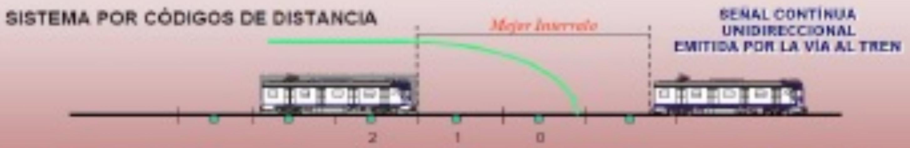
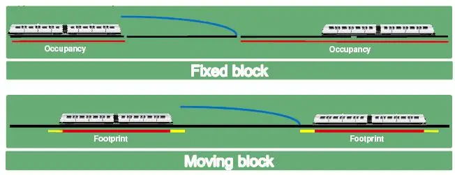
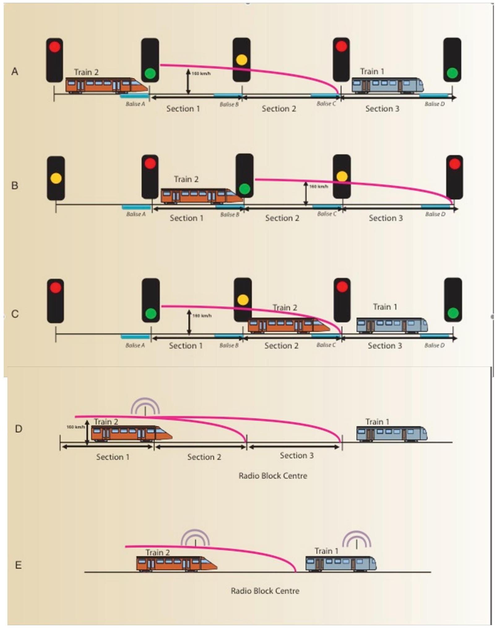
Moving Block System
Alternatively, there exists moving block approach, where protection zone shifts dynamically together with train. Instead of fixed predetermined cantons in infrastructure, system continuously calculates required braking distance based on current train speed and its characteristics, creating a “protection block” that moves with train. This significantly optimizes line capacity by allowing shorter and dynamically adaptable separation distances.
V.3. ERTMS
ERTMS (European Rail Traffic Management System) constitutes comprehensive European system for train control, command, and signalling. It was conceived and developed in early 1990s with aim of creating European standard system that could be applied throughout continental railway network, facilitating cross-border interoperability and general technological modernization.
ERTMS System Composition
ERTMS is structured around two main subsystems working in integrated manner:
-
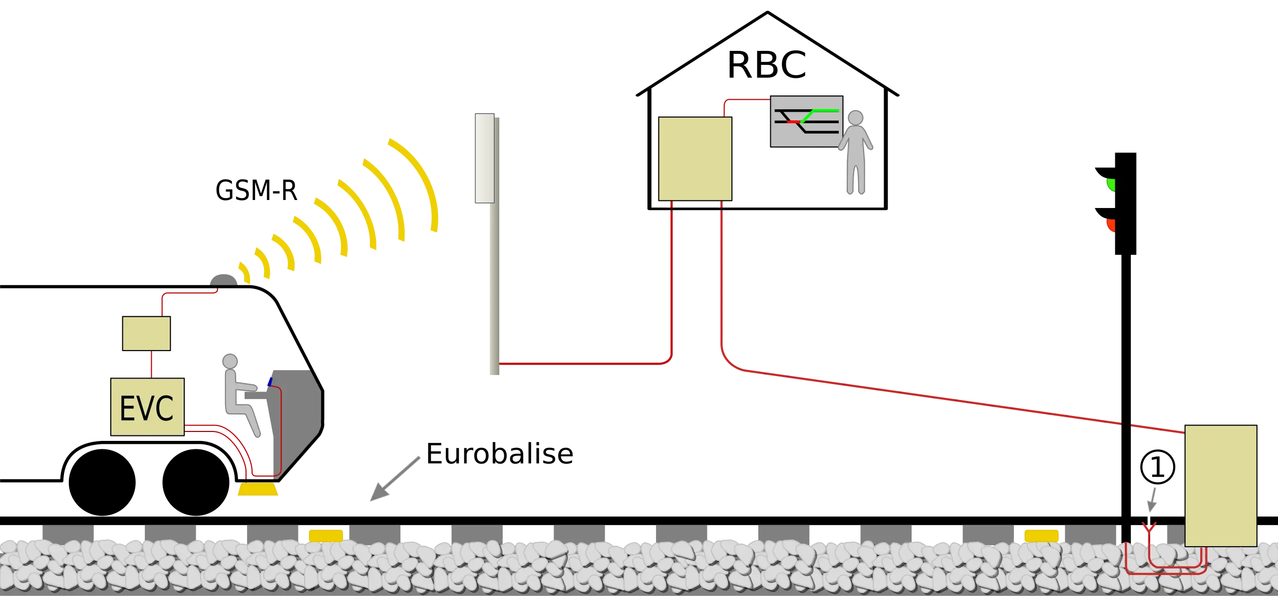
GSM-R (Global System for Mobile communication - Rail): based on standard GSM technology but specifically adapted for railway applications, using specialized railway sector frequencies and incorporating advanced safety and reliability functions. GSM-R constitutes fundamental telecommunications system allowing bidirectional exchange of voice and data information between terrestrial infrastructure equipment and onboard train equipment.
-
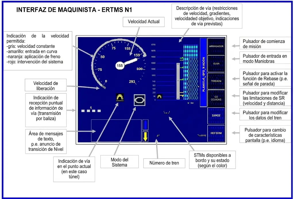
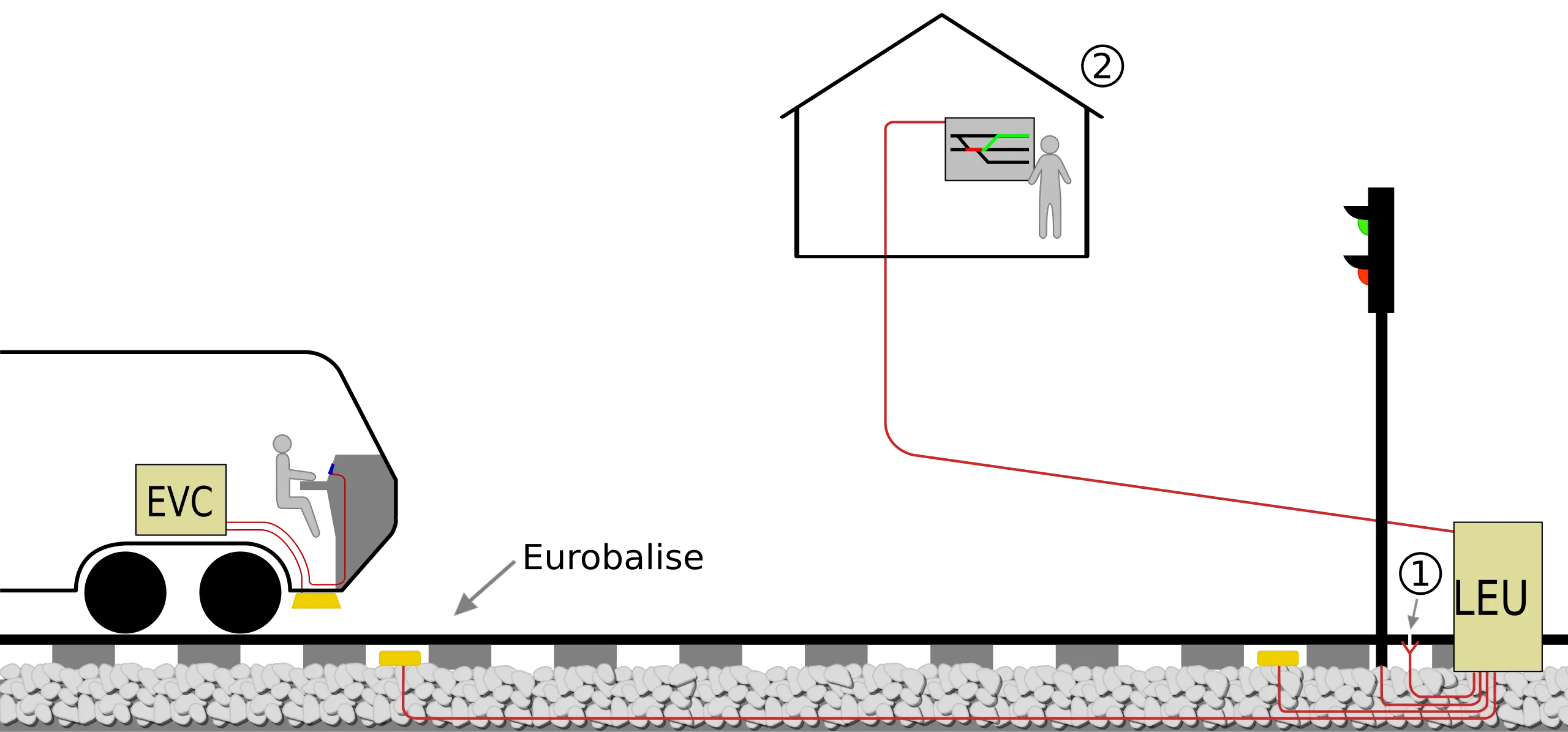
ETCS (European Train Control System): is subsystem through which regulatory information is transmitted from infrastructure to train. A specialized onboard computer, called Eurocab, continuously receives information on maximum authorized speed in each itinerary section. This computer constantly compares actual train speed with maximum permitted speed, and in case of detecting violation of this limit, automatically orders train braking to restore compliance.
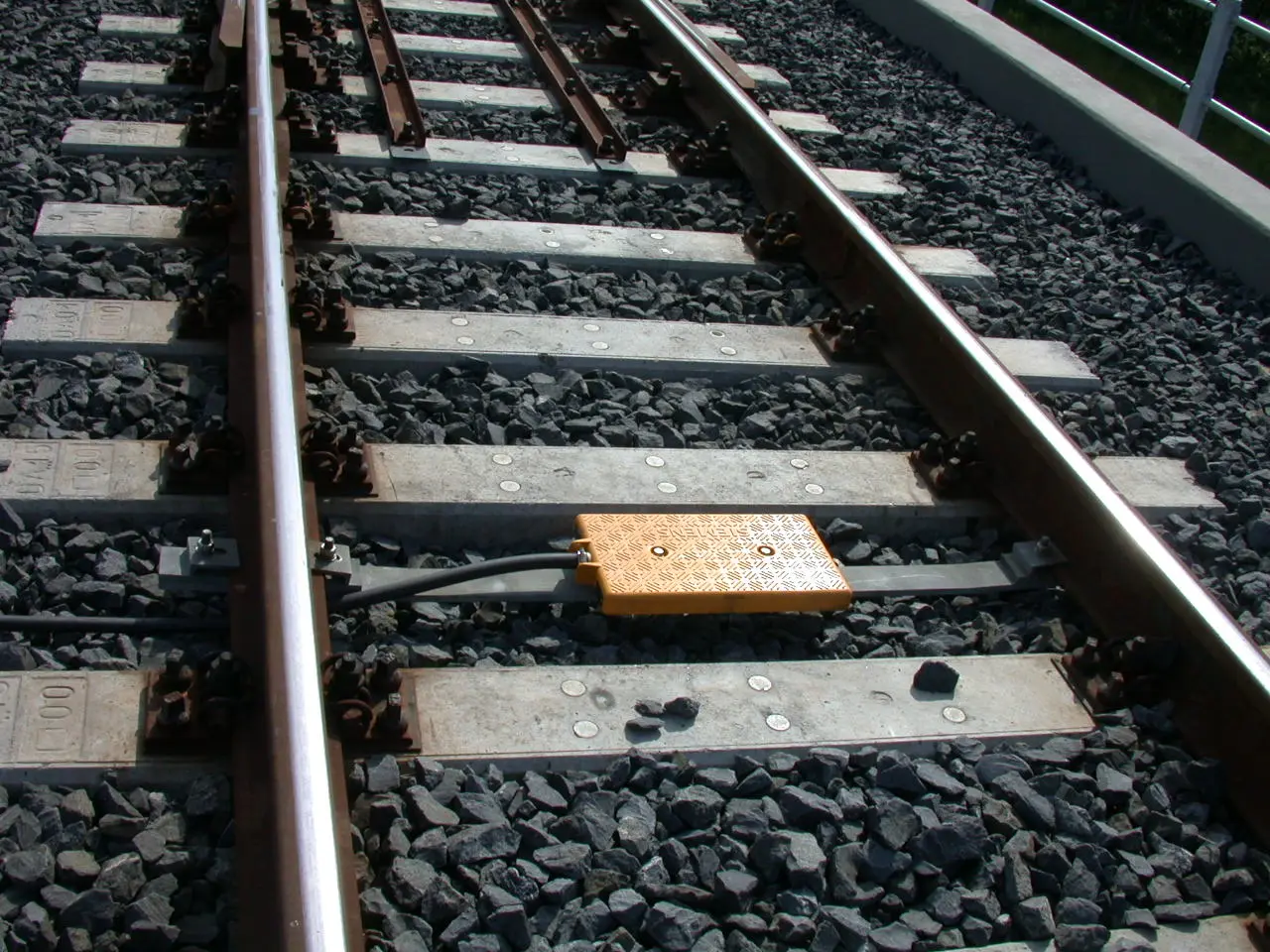 Eurobalise
ERTMS Implementation Levels
Degree of ERTMS functional implementation on specific line depends directly on technical equipment installed in infrastructure and rolling stock. Several implementation levels have been established, each with progressively advanced capabilities:
-
Level 0: ETCS in limited configuration, restricted only to monitoring punctual maximum speed at specific critical locations.
- Level 1: Punctual transmission of speed information via devices called Eurobalises. Onboard ETCS equipment continuously calculates and supervises authorized speed based on information received from these beacons.
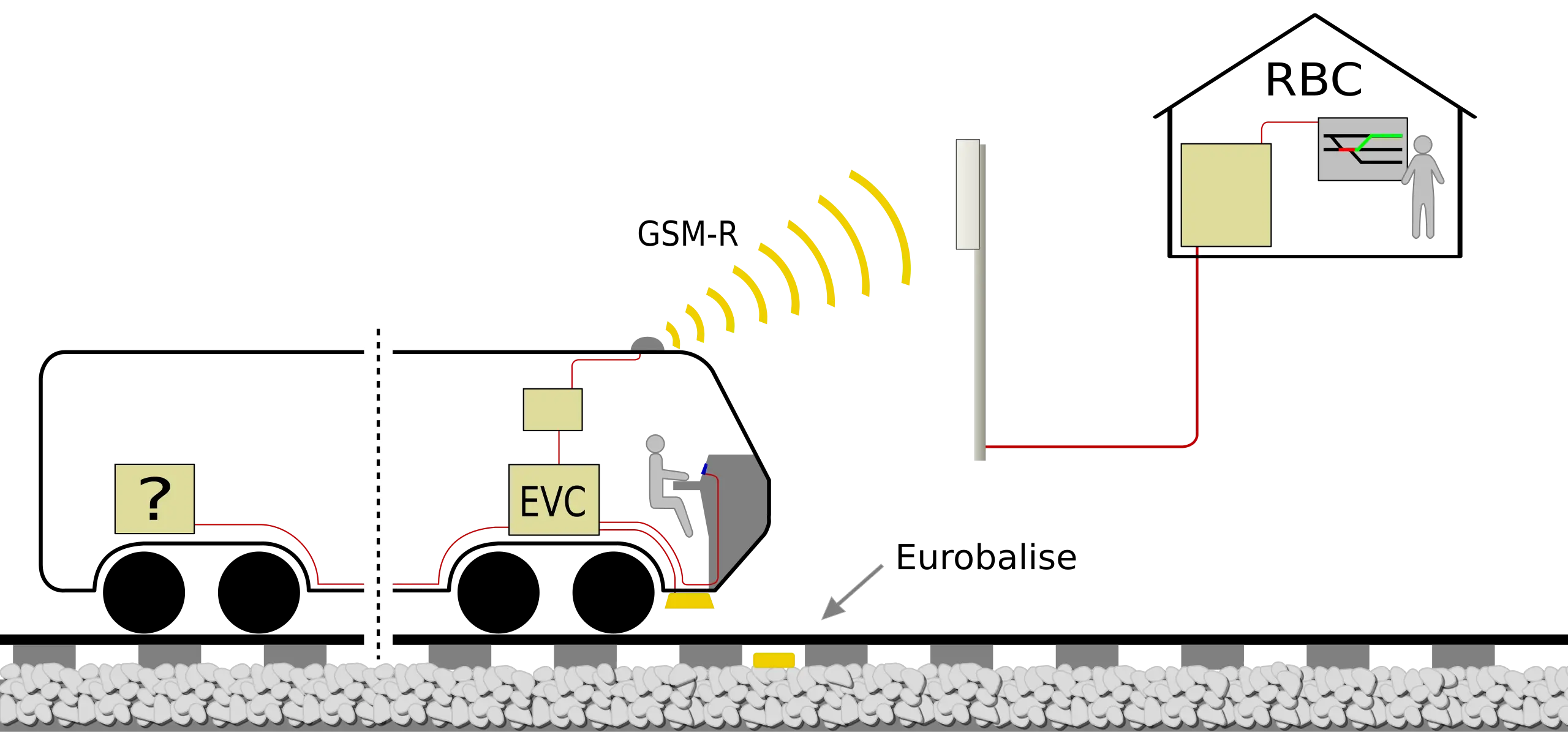
- Level 2: Continuous speed supervision via permanent communication. Train positioning is continuously transmitted via GSM-R communications system, allowing infrastructure to know exact train position at all times and send dynamic speed authorizations.
- Level 3: Evolution of Level 2 but with elimination of fixed track circuits in infrastructure, replacing them completely with moving blocks controlled via position information. This level represents most advanced technology and is still in development and pilot testing phase in several European countries.
ATP Systems: ERTMS
ATP Systems: ERTMS
Chapter VI Control Centers
Railway traffic management in Spain has undergone a radical transformation from mid-20th century manual methods to implementation of integrated digital control ecosystems placing country at world technological forefront. Centralized Traffic Control (CTC) is defined as fundamental technological solution allowing remote command of interlockings, devices managing network signalling and diversions in real time remotely, establishing safe itineraries for train circulation 24 hours a day. This technical architecture not only guarantees operational safety but acts as capacity multiplier necessary to absorb traffic growth derived from sector liberalization and high-speed network expansion.
VI.1. Historical evolution and control system maturity
CTC trajectory in Spain reflects country’s industrial evolution. Foundational milestone is situated in April 1954, with entry into service of first section controlled by this technology on Brañuelas-Ponferrada single track route. That initial installation, using US-origin GRS technology, marked beginning of overcoming local traffic cabinets as sole management method. From this experience, network began modernization process accelerated significantly in subsequent decades.
During 70s, first geographic interlockings were introduced and, in 1976, first computer-based CTC, allowing transition from electromechanical logic to data processing-based one. The 90s meant definitive leap with inauguration of first Madrid-Seville high-speed line in 1992, incorporating advanced protection systems such as LZB and laying foundations for modern Regulation and Control Centers (CRC) development.
| Historical Stage | Period / Year | Main Technology Milestone |
| CTC Origin | 1954 | Inauguration of Brañuelas-Ponferrada section (GRS Technology). |
| Electronic Transition | 1970 - 1980 | First computer-based CTC (1976) and geographic interlockings. |
| HS Revolution | 1992 | LZB signalling and automatic protection on Madrid-Seville HSL. |
| Integral Digitalization | 2000 - Present | Development and implementation of Da Vinci system and multi-network centers. |
Railway history in Spain is also marked by complexity of its orography and evolution of its operating companies. Before unification into RENFE in 1941, large companies like Norte, MZA, and Andaluces managed network under legislative frameworks dating from 1855 and 1877. Slow initial development, conditioned by low population density and political turbulence, was overcome via strategic plans like 1926 Preferential Plan for Urgent Construction, seeking to improve communications with Portugal and peninsular transversals. This heritage of scattered lines and heterogeneous technologies is what modern CTC has managed to unify under cohesive operational command.
VI.2. Operational structure and network management hierarchy
Administration of Spanish railway infrastructure, under responsibility of Adif and Adif Alta Velocidad, is organized via hierarchical structure designed to maximize resilience and efficiency. Top rung of this pyramid is occupied by H24 Network Management, permanent supervision unit monitoring global infrastructure status and traffic development throughout national territory.
VI.2.1. Regulation and Control Centers (CRC) and Command Posts (PM)
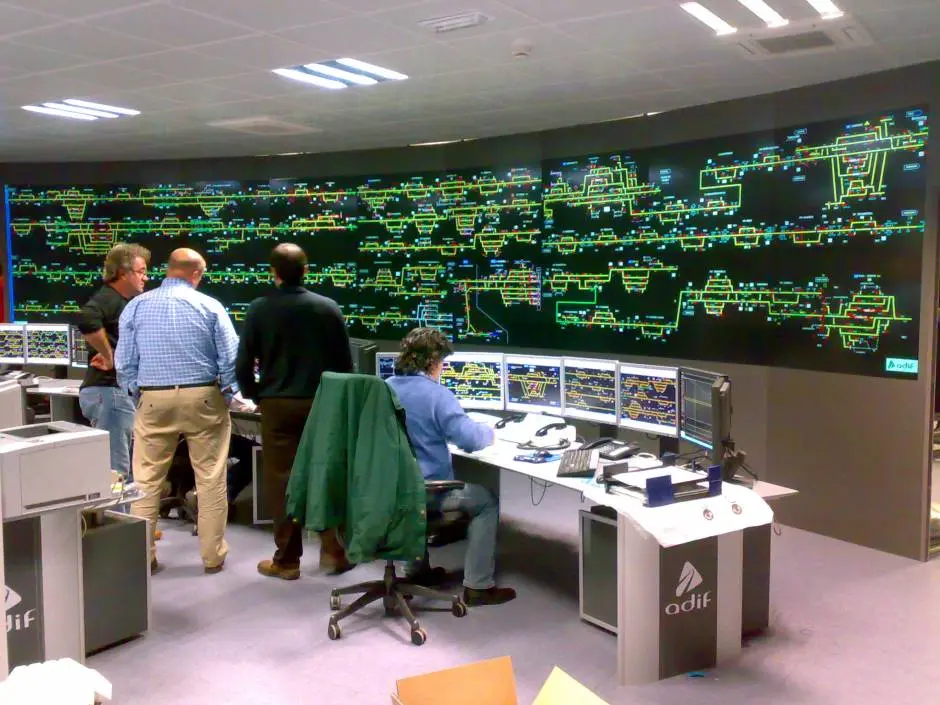
Network is physically managed through 20 main operating centers. There is fundamental technical distinction between so-called Regulation and Control Centers (CRC), dedicated exclusively to High Speed Network, and Command Posts (PM), managing Conventional Network and Metric Gauge Network (RAM). These centers act as railway system brain, collecting all necessary information to guarantee flow of scheduled services, including schedules, stops, and track assignment.
| Center Type | Number | Managed Network | Kilometers (approx.) |
| High Speed CRC | 4 | Standard Gauge Network (HSL) | > 4,000 km. |
| Conventional / RAM PM | 16 | Iberian Gauge and Metric Gauge | > 11,500 km. |
Geographic distribution of these centers responds to regional optimization and technical coverage criteria. Among most prominent centers are Madrid-Puerta de Atocha and Albacete for high speed, and centers like Madrid-Chamartín, Barcelona, Valencia, Seville, León, and El Berrón for conventional and metric network. Each center supervises specific sections; for example, Manzanares PM regulates from Aranjuez to Alcázar de San Juan and lines towards Extremadura, while Albacete CRC manages corridor towards Levante.
VI.2.2. Traffic Cabinets and support services
Despite high degree of centralization permitted by CTC, infrastructure maintains Traffic Cabinets at key stations. These dependencies are attended by personnel managing traffic locally through interlockings, acting as proximity control points. Complementarily, Itinerant Traffic Services (SIC) provide necessary flexibility to open additional cabinets when traffic demand or exceptional situations require.
In normal operating situations, interaction between PM regulator and station personnel is constant. Command Post monitors circulation mesh (graph), where each train is diagonal line; any deviation from theoretical schedule is communicated and managed to minimize impact on rest of network. This technical dialogue allows adjusting crossings and passage priorities, especially on single track lines where precision is critical to avoid chain delays.
VI.3. Da Vinci System: Innovation and technological sovereignty
Da Vinci system represents Adif’s greatest technological achievement in traffic management field. Developed entirely in Spain in collaboration with Indra, Da Vinci is integrated management platform bringing together all necessary subsystems for railway control in single interface. Its architecture is based on railway services bus acting as interconnection software, allowing real scalability from individual lines to complex national networks.
VI.3.1 Functional modules and software architecture
System power lies in modular division covering complete railway business lifecycle, from planning to historical operational analysis. Key Da Vinci components include:
-
iTracker: System heart, intelligent train tracking service integrating information from multiple subsystems to perform continuous and real monitoring of each composition on network.
-
iRouter: Logical brain, advanced conflict prediction and detection module automating train routing, reducing manual operator workload.
-
Regulation Management System (SGR): Provides essential visual tools, such as tracking meshes, track occupancy viewers, and real-time replanning tools.
-
DICOM Integration: Unifies fixed and mobile telephony communications (GSM-R) within operating environment, guaranteeing regulator has immediate contact with drivers and infrastructure personnel.
| Da Vinci Module | Main Function | Operational Benefit |
| iTracker | Real-time tracking | Absolute precision in rolling stock location. |
| iRouter | Automatic routing | Minimization of human errors and slot optimization. |
| SGR | Regulation interface | Intuitive visualization of operation and incident management. |
| DICOM | Integrated communications | Agility in voice/data operational coordination. |
Da Vinci is not only national standard, used on all Spanish high-speed lines and metric gauge network, but has been successfully exported to international networks like those of Morocco, Lithuania, and Medellín Metro in Colombia. Its ability to adapt to different hardware environments and compliance with European regulations like EIRENE (for GSM-R) make it one of most advanced systems in world.
VI.4 Multi-Network Center paradigm: Efficiency and integration
Adif is promoting new operating model called “Multi-Network CRC”, aiming to concentrate management of lines with different track gauges and technical characteristics in single physical location. This approach allows leveraging synergies, optimizing human resources, and improving control reliability by having all management tools in unified environment.
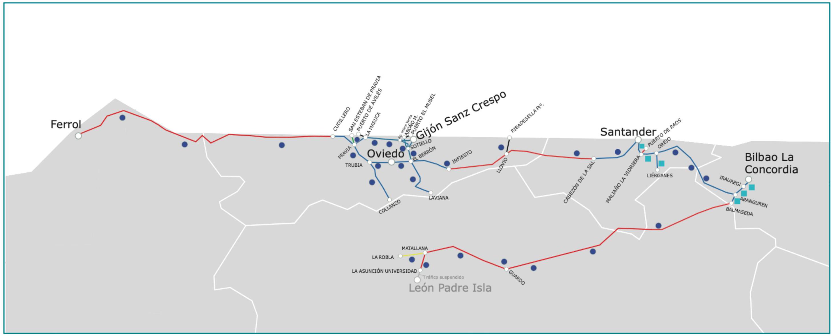
VI.4.1 El Berrón Center and RAM modernization
El Berrón CRC, in Asturias, constitutes paradigmatic example of this model. This center integrates management of 222 km of regional conventional gauge network (previously controlled from Oviedo) with more than 750 km of Metric Gauge Network (RAM). In total, nearly 80 professionals manage from this point 976 km network on which almost 600 trains run daily.
Creation of these centers is accompanied by deep technological renewal. In El Berrón, as well as in Santander and Bilbao, CTC renewal for metric gauge network has been completed, integrating them into modern platforms replacing obsolete systems like STAC Rail. These new centers are equipped with latest generation videowalls, financed partly by NextGenerationEU European funds, offering panoramic and detailed view of entire supervised network.
| Multi-Network Center | Integrated Networks | Management Scope |
| León | High Speed, Iberian and RAM | More than 1,200 km of railway network. |
| El Berrón | Iberian and Metric Gauge (RAM) | Railway network of Asturias (976 km). |
| Bilbao | Iberian and RAM | 544 km of lines in Basque Country. |
| Santander | Iberian and RAM | 258 km of lines in Cantabria. |
This multi-network model will extend soon to Ourense, with new center projected for 2025 doubling current surface area and allowing simultaneous management of Galician high speed, conventional, and metric networks.
VI.5 Energy Telecommand and auxiliary safety systems
Safe operation of railway network does not rely solely on train control, but also on critical state of electrical infrastructure and safety detection elements. Energy Telecommand is SCADA system allowing remote supervision and actuation of electrical substations and catenary.
VI.5.1. Energy Telecommand Architecture
Historically managed independently, Energy Telecommand is increasingly integrated into CRC and PM environment to facilitate coordination in face of electrical incidents. Its architecture consists of:
-
Central Posts: Located in CRCs, from where energy operators supervise 2,200 V network status and traction substations.
-
Local Operation Posts (PLO): Situated next to track for local maintenance maneuvers with limited visualization.
-
Dedicated VPN Networks: Connectivity is guaranteed via virtual private networks over fiber optics, ensuring command orders travel securely and segregated from general data traffic.
VI.5.2. Additional detection and protection systems
Modern CTC receives and processes alarms from multitude of sensors deployed on track. TISEF (Integral Railway Sensorization Telecommand) system is product responsible for bringing together this heterogeneous information. Integrated devices include:
-
Hot axle box detectors: Infrared sensors measuring grease box temperature to prevent fires or derailments.
-
Dragging and fallen object detectors: Alert if train has detached elements or obstacles have fallen onto track, especially in tunnels and overpasses.
-
Wind and snow detectors: Critical in high-speed network for adjusting maximum speeds in adverse weather conditions.
Integration of these systems into unique “visualization layer” allows traffic regulator, upon hot axle alarm, to receive alert simultaneously to physical detection, being able to stop train immediately via direct order or through telemanded signalling.
VI.6. Network Modernization: Telephone Block Suppression Plan
One of pillars of Adif’s safety strategy is progressive elimination of telephone blocks in conventional network. Telephone blocking is manual management method where traffic safety between two stations depends on telephone messages exchanged between traffic agents. Although safe under strict compliance with rules, its automation eliminates human error factor and drastically increases line capacity.
VI.6.1. Investment and technological deployment
Adif is executing massive investment plan to replace these manual blocks with Automatic Blocking systems (like BLAU or BLAD) telemanded from CTC. These actions include:
-
Installation of electronic interlockings: Allowing digital safety logic instead of old mechanical or electrical ones.
-
Fiber optic and GSM-R deployment: To guarantee robust communications between track and control center.
-
Use of satellite technology: In specific low traffic density sections, such as Cáceres-Valencia de Alcántara route, satellite communication systems are being implemented to connect train with CRC efficiently.
| Sections under Modernization (Examples) | Estimated Investment | Project Objective |
| Badajoz and Huelva lines | > €38.6 M | Suppression of telephone blocking and GSM-R deployment. |
| Villanueva de la Serena - Brazatortas | > €34 M | Integral renewal of signalling and safety. |
| Cáceres - Valencia de Alcántara | > €9 M | Replacement by telemanded automatic and satellite system. |
| Bobadilla - Ronda | Part of €470 M | Platform improvement, electrification, and block suppression. |
This update process not only improves installation reliability but contributes to Sustainable Development Goals (SDGs), specifically SDG 9, by fostering resilient and quality infrastructures.
VI.7. Impact on capacity, safety, and liberalization
Existence of powerful and flexible centralized control system is “sine qua non” condition for railway passenger transport liberalization in Spain. By automating repetitive operations (like signal telecommand), regulators can concentrate on replanning and capacity management in market where multiple operators now coexist.
VI.7.1. Operation and safety statistics 2024-2025
2024 operating data reflect network in maximum activity, successfully supervised from control centers. General interest railway network (RFIG) has over 15,600 km of lines, of which over 11,600 km are under direct regulation of management centers.
| Operational Indicator | 2024 Data | Observations |
| Trains in circulation supervised | 1,800,563 trains | Record figure reflecting high usage intensity. |
| Investment in works and maintenance | > €5,600 M | Includes conventional line renewal and new lines. |
| Notified events (CIAF) | 123 events | Strict monitoring of operational safety. |
| Freight train-kilometers | 24.7 million | Despite slight 1.77% annual decrease. |
| Passenger growth (2025 est.) | 44 million | 13% more compared to 2024, driven by liberalization. |
Safety is guaranteed via automated protection systems like ASFA Digital and ERTMS, whose implementation is continuously monitored from CRCs. In 2024, significantly lower number of accident “precursors” (such as Signal Passed at Danger or rail breaks) was registered compared to years prior to 2022, validating control technology investment strategy.
VI.7.2. Resilience and remote backup systems
One of most critical innovations integrated into CTC renewal (with €72 M budget) is backup system. This design allows, in face of serious incident in main system or physical CRC building, another center to “supplant” its functions remotely. This decentralized management capability guarantees railway traffic does not stop due to technical or territorial failures, allowing regulation of sections even from opposite end of Peninsula in extreme emergency cases.
VI.8. Future of Control Centers: AI, SITRA+ and BIM
Adif is immersed in its 2030 Strategic Plan, where digitalization and intelligent automation are dominant vectors. Control center evolution is not limited to updating hardware, but changing operating model towards proactive systems.
VI.8.1. SITRA+ System and Artificial Intelligence
Developed internally since 2018, SITRA+ system represents generational leap in traffic regulation. This tool integrates multiple previous applications into single platform and incorporates Artificial Intelligence algorithms to automatically determine best train entry and exit routes in complex stations. SITRA+ allows real-time visualization of track occupancy and automatic router/numberer drastically reducing decision-making latency.
VI.8.2. BIM Methodology and Digital Twins
Implementation of BIM (Building Information Modeling) methodology in railway infrastructure allows optimized asset management throughout lifecycle. For control centers, this translates into ability to have “digital twins” of infrastructure, facilitating regulator knowing not only train position but health status of each physical track component, optimizing maintenance campaigns and reducing unforeseen breakdowns.
VI.9. New horizons in Metric Gauge Network and rural lines
Future also contemplates specific technological solutions for low density lines. ERTMS standards (Level 3 with satellite support) are being developed requiring less physical equipment on track and lower maintenance costs, maintaining safety standards of high-speed lines. These systems will be managed entirely from existing CRCs, allowing democratization of advanced safety throughout railway geography.
Chapter VII. Conclusion
The set of systems, devices, and safety methodologies described in previous chapters constitute fundamental pillars upon which safe, efficient, and reliable operation of modern railway infrastructures is sustained. From classic signalling and blocking mechanisms to most advanced automatic train protection systems, each component plays essential role in accident prevention and transport capacity optimization.
Continuous technological evolution, evidenced in development of systems like ERTMS, demonstrates permanent commitment of European railway sector to improve safety, interoperability, and operational efficiency. Deep understanding of these systems, their integrated functioning, and underlying principles is fundamental for any professional involved in operation, maintenance, or design of railway infrastructures.
Review Questions
How is the concept of risk defined in railway safety?
As the combination resulting from the probability of occurrence of an accident and the severity of harm that it could occasion.
What are the two fundamental and often conflicting objectives of railway signalling?
Guarantee maximum safety in circulation and achieve greatest possible efficiency and capacity of transport.
What function does a Blocking system fulfill?
It guarantees exclusive reservation of a track section or canton, ensuring only one train can occupy it at a given time to avoid collisions.
What does an interlocking consist of?
It is the system establishing dependency between signals and track apparatus, preventing movement authorization if route is not correctly configured and secured.
What is the main difference between Level 1 and Level 2 of ERTMS system?
Level 1 transmits information punctually via Eurobalises, while Level 2 maintains continuous communication between train and infrastructure via GSM-R.
Bibliography
- Díaz de Villegas, J.M. (2003) Ferrocarriles. Apuntes de clase. E.T.S. Ing. Caminos, Canales y Puertos Santander.
- García Álvarez, A. (2022) Manual de ferrocarriles. El sistema ferroviario español. Ed. Garceta.
- https://www.adif.es/sobre-adif/conoce-adif/declaracion-sobre-la-red
- González, F.J. (2009) Señalización ferroviaria: del guardagujas a la operación sin conductor
- Lopez Pita, A. (2008) Explotación de líneas de ferrocarril. Ediciones UPC. Barcelona.
- Losada, C.A. (2009) Señalización Ferroviaria: La interoperabilidad y el sistema ERTMS. I Jornadas de Tecnología Ferroviaria, Noviembre 2009.
- Melis, M \& Gonzalez, F.J. (2008) Ferrocarriles Metropolitanos. Tranvías, metros ligeros y metros convencionales. Colegio de Ingenieros de Caminos Canales y Puertos. Madrid.
- Montes Ponce de León, F. (2011) Los sistemas de control de tráfico y señalización en el ferrocarril. Publicaciones de la Universidad Pontificia de Comillas
- https://www.comofuncionanlostrenes.es/instalaciones-de-seguridad-enclavamientos/
- https://www.sindicatoferroviario.com/DOCUMENTACION/CIRCULACION/RGC/mci/mci11_6.htm
- La transformación de los Centros de Regulación de Circulación (CRC)
- Sistema DaVinci - Oposiciones Técnicos Ferroviarios
- Adif invierte 72 M€ en reforzar la gestión del tráfico ferroviario convencional y de Cercanías
- El Centro de Control como punto neurálgico del tráfico ferroviario
- Informe Anual 2025 Agencia Estatal de Seguridad Ferroviaria
On this page