Railway Rolling Stock: Concepts, Classification and Technologies
Table of Contents
- Chapter I. Introduction
- Chapter II. Traction
- Chapter III. Hydrogen propulsion: emerging technology for the railway future
- Chapter IV. Railway Composition Architecture
- Chapter V. Fundamental Components of Rolling Stock
- Chapter VI. Gauge Specifications: Dimensional Envelopes of Railway Vehicles
- Chapter VII. Lower Part Gauge Specifications: Vehicle Lower Envelopes
- Chapter VIII. Axle, Wheel and Bogie Systems: Running Gear Configurations
- Chapter IX. Locomotives: Classification, Nomenclature and Axle Configurations
- Chapter X. Railway Tractors (Shunters): Specialized Maneuvering Machines
- Chapter XI. Towed Stock: Classification and Constructive Characteristics
- Chapter XII. Freight: Typology, Characteristics and Compositions of Freight Wagons
- Chapter XIII. Coupling Systems: Mechanical, Pneumatic and Electrical Coupling
- Chapter XIV. Passenger Transport: Passenger Coaches and Composition Architecture
- Review Questions
- Bibliography
Chapter I. Introduction
In the context of railway engineering, rolling stock is defined as all vehicles equipped with wheel systems capable of moving on railway infrastructure. This concept encompasses a wide range of specialized equipment designed for the efficient transport of both passengers and freight.
When we refer to a train, we are talking about an integrated configuration of one or more vehicles intended for rail transport, which are mechanically connected and operate on a common railway infrastructure. These compositions can adopt different configurations depending on their specific functions:
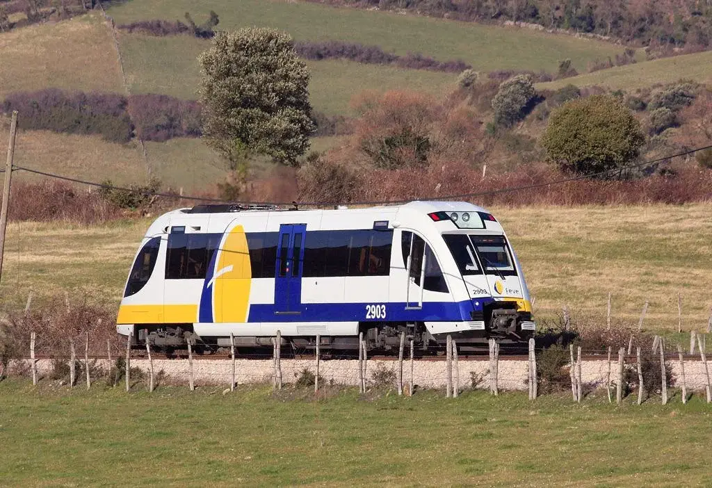
- Autonomous units consisting of a single vehicle, which can be a locomotive or a self-propelled railcar
- Compositions made up of one or more motive units that exert traction on a set of towed vehicles, whether passenger coaches or freight wagons
- Multiple formations consisting of various self-propelled systems operating in a coordinated and connected manner.
CLASSIFICATION BY TYPE OF SERVICE
The fundamental classification of rolling stock is based on the operational function it performs within the transport system. This differentiation is critical to understanding the design and operation parameters of each typology.
PASSENGER TRANSPORT SERVICE
Trains intended for the transport of people are characterized by a series of specific operational and technical parameters that condition their design and operation:
- Maximum permissible operating speeds on circulation lines
- Infrastructure electrification characteristics and requirements
- Signaling and traffic control systems
- Dimensional compatibility with available track gauge
- Projected travel times and service regularity
- Distribution and accessibility of stations
- Provision of services and amenities for users
FREIGHT TRANSPORT SERVICE
Systems dedicated to cargo transport present a different set of technical and operational specifications aimed at maximizing capacity and profitability:
- Minimum circulation speeds established by operating regulations
- Ability to overcome ramps and complex altimetric profiles
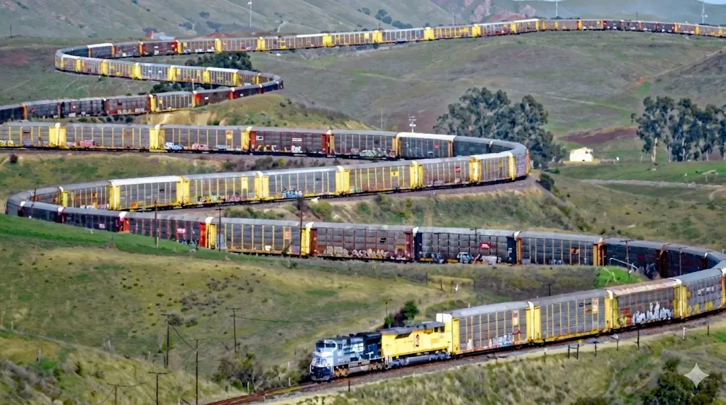
- Maximum permissible train length
- Specific infrastructure electrification requirements
- Dimensional compatibility with existing track gauge in the network
- Arrangement of cargo terminals and modal transfer points
- Reliability and operational availability indices of the equipment
Performance and Specifications
A fundamental aspect in defining the performance of any railway equipment is that each technical specification must include both the required numerical value and the specific environmental and operational conditions under which that value is valid and must be guaranteed. This practice ensures that all stakeholders share a clear understanding of what is expected from the system.
Performance evaluation is structured into several hierarchical levels of analysis ranging from individual components to complete vehicle performance:
- Performance at subsystem and individual component level
- For example: parameters such as energy autonomy of battery systems for onboard equipment, interior lighting levels, thermal capacity of HVAC systems, compressor duty cycles for auxiliary systems, data storage capacity in event recorders, and functionalities available in integrated passenger information systems
- Performance of the complete vehicle assembly
- Mechanical resistance of the body structure considering longitudinal and vertical loads, as well as energy absorption in impacts and dynamic stresses
- Structural robustness of bogie and frame systems
- Dynamic stability during running under different track conditions
- Kinematic performance, including maximum speeds and available acceleration profiles
- Dynamic performance related to internal and external forces generated during operation
- Operational performance encompassing capability to operate on complex line profiles, projected travel times, passenger transport capacity, load hauling capacity, RAMS indicators (Reliability, Availability, Maintainability, and Safety), and Life Cycle Cost (LCC) analysis
Chapter II. Traction
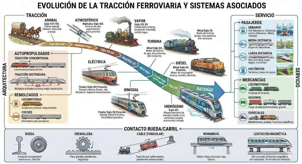
The selection of the traction system constitutes one of the most determining decisions in the design of any railway vehicle, as it directly conditions the required infrastructure, operational costs, environmental sustainability, and available performance. Throughout railway history, multiple traction technologies have been developed reflecting the technological evolution and operational needs of each era.
II.1. BY TYPE OF TRACTION → ANIMAL / ATMOSPHERIC / STEAM / TURBINE
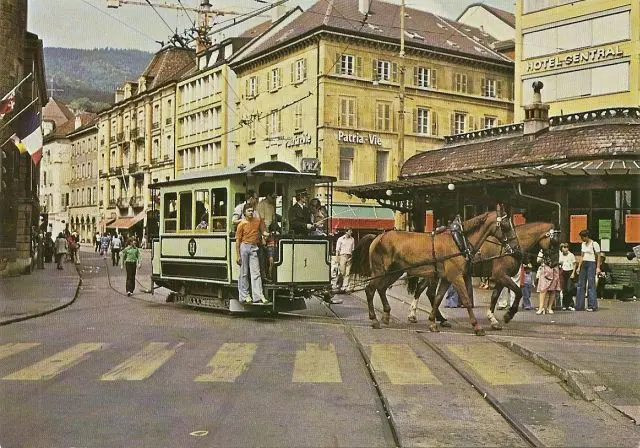
ANIMAL TRACTION
Animal traction represents the most primitive form of railway propulsion and marks the origins of the railway as a transport system. Although currently practically obsolete, animal traction was fundamental in the first railways, particularly in mining applications and short-distance transport where the load capacity and traction of animals such as horses, mules, and oxen were utilized.
ATMOSPHERIC TRACTION
Atmospheric propulsion constitutes a fascinating chapter in the history of railway engineering. This innovative system was based on the creation of a pressure difference between the atmosphere and a vacuum system generated by pneumatic tubes arranged between the rails. Operation was carried out by vacuum engines that took advantage of this pressure difference to generate movement. Although it represented an important technological advance, this technology was eventually abandoned due to inherent limitations, operational problems, and economic disadvantages that made its continuity unviable compared to more practical solutions.
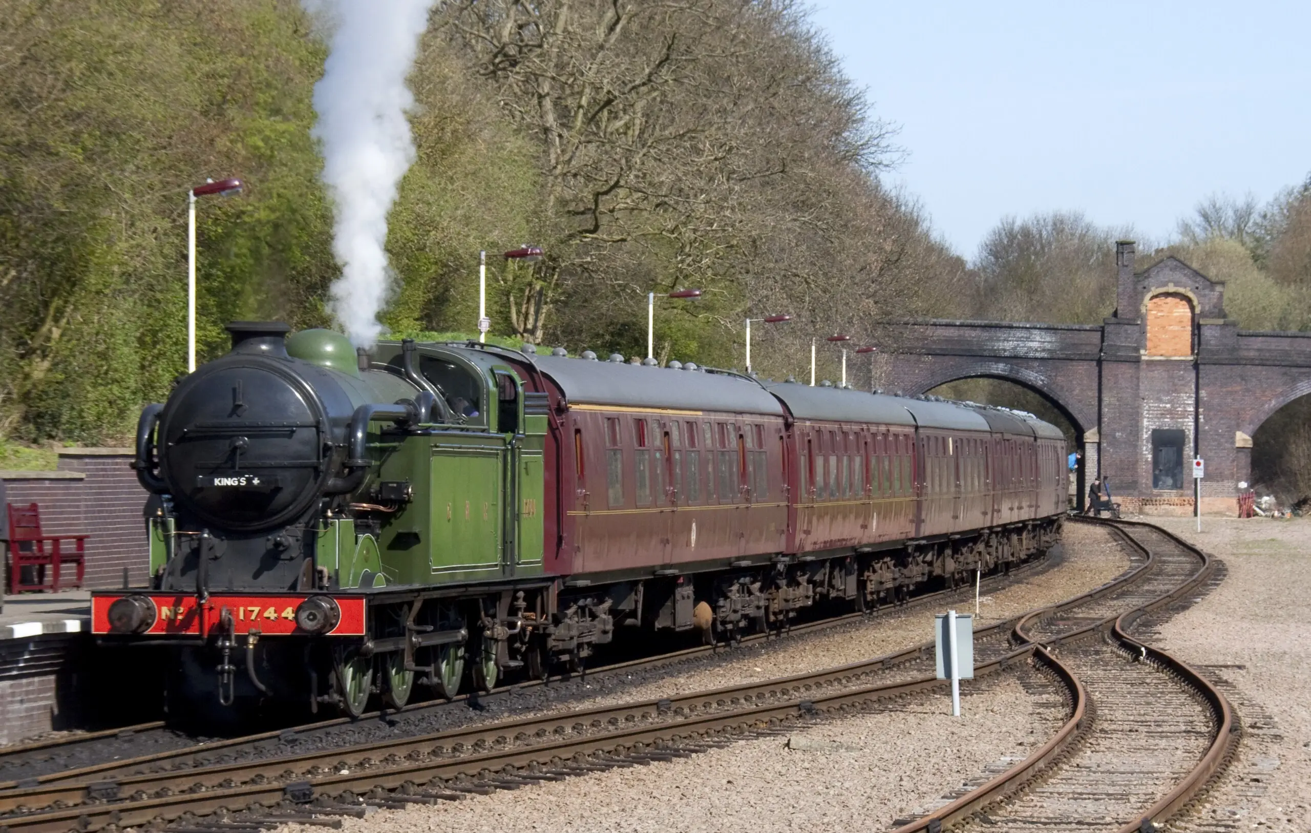
STEAM TRACTION
Steam propulsion represents the true industrial revolution in railway transport. This innovative system generated movement using water vapor generated in boilers, which acted on pistons connected directly to the vehicle’s driving wheels. The steam era was a golden age of the railway that spanned more than a century. However, with the appearance and consolidation of more modern technologies, particularly diesel and electric traction, the steam era came to an end, currently reduced to historical applications and heritage preservation.
TURBINE TRACTION
Propulsion using turbines has had a fundamentally testimonial implementation in the railway context, not managing to consolidate itself as a mainstream traction system. Although in other sectors turbines proved to be viable technologies, in the railway field they were quickly surpassed by the development of diesel and electric traction. The relative advantages they offered in certain contexts were insufficient to counteract the operational limitations, maintenance problems, and economic disadvantages that characterized these systems.
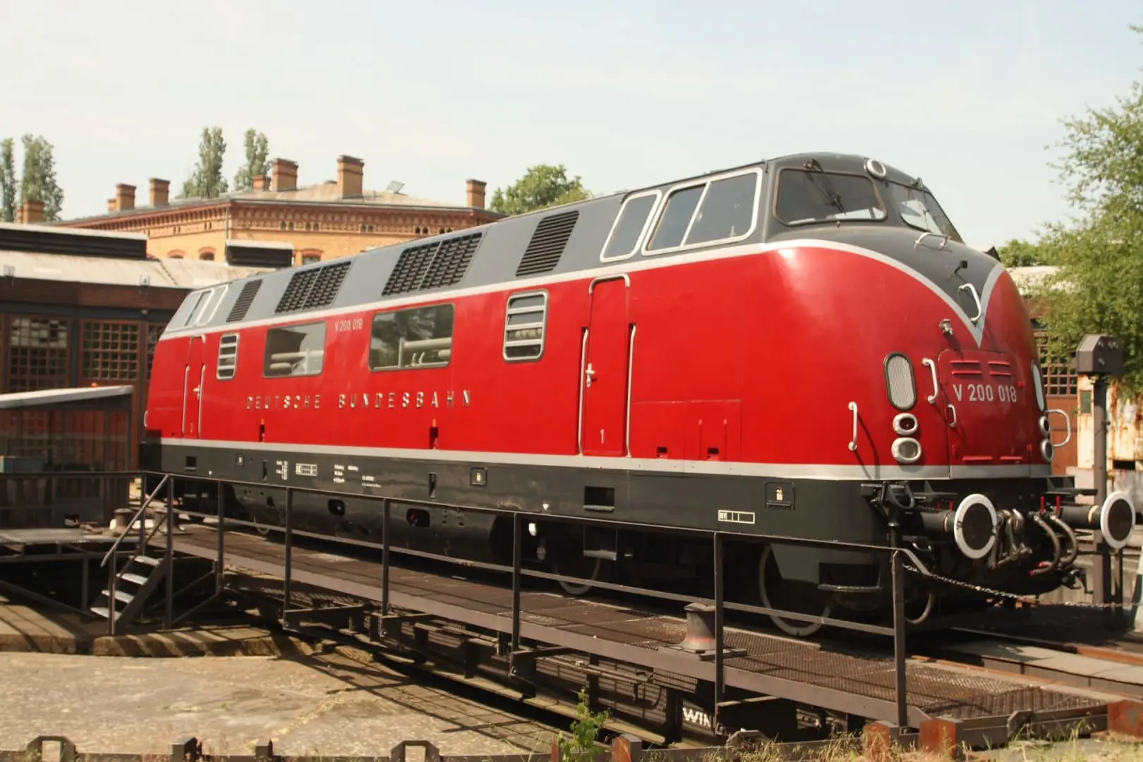
II.2. BY TYPE OF TRACTION → DIESEL
GENERAL CHARACTERISTICS OF THE DIESEL TRACTION SYSTEM
Propulsion using diesel internal combustion engines represents an important milestone in the evolution of railway transport. It is a deeply developed technology that offers significant advantages in multiple operational and economic aspects.
Among the fundamental advantages are: operational autonomy capacity thanks to fuel storage capacity, allowing the vehicle to function independently of fixed external infrastructure; low cost associated with infrastructure implementation compared to electrified systems; and technological maturity allowing reliable operation and well-established maintenance.
However, this technology also presents significant disadvantages: emission of polluting gases contributing to climate change and affecting air quality, particularly in urban areas; generation of noise pollution affecting quality of life near railway lines; and dependence on non-renewable fossil resources.
CLASSIFICATION OF DIESEL SYSTEM BY TRANSMISSION TYPE
The way in which the power of the diesel engine is transmitted to the driving wheels is decisive for the vehicle’s operational and performance characteristics. Three main approaches have been developed:
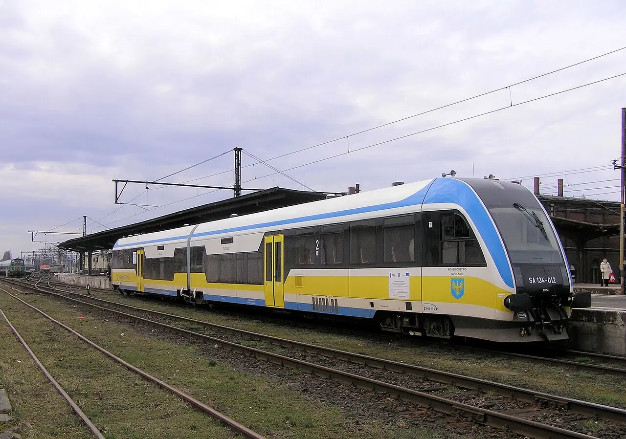
- DIESEL-MECHANICAL (DMU): Uses mechanical transmission
- DIESEL-HYDRAULIC (DMU): Uses hydraulic transmission
- DIESEL-ELECTRIC (DEMU): Uses electrical generation systems
DIESEL LOCOMOTIVE DMU (DIESEL MULTIPLE UNIT)
II.2.1. DIESEL-MECHANICAL TRANSMISSION (DMU)
This mechanical transmission system transmits engine power directly through mechanical components such as gears and clutches. The fundamental characteristic is the direct mechanical connection between the combustion engine and the driving axles, allowing immediate transmission of forces.
II.2.2. DIESEL-HYDRAULIC TRANSMISSION (DMU)
In this system, engine power is transmitted through a fluid medium, typically oil under pressure, acting on hydraulic components such as pumps and motors. This type of hydraulic transmission offers a smoother transition between speeds and better adaptation of the engine to variable operating conditions.
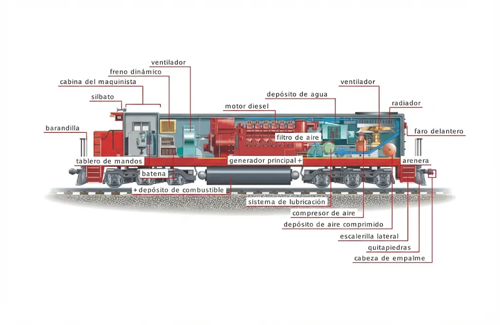
II.2.3. DIESEL-ELECTRIC TRANSMISSION (DEMU)
In this approach, the diesel engine acts as a generator of electrical energy, which is subsequently converted into movement by electric traction motors. This electric transmission system offers significant flexibility in traction effort control and has proven to be very efficient in multiple railway applications.
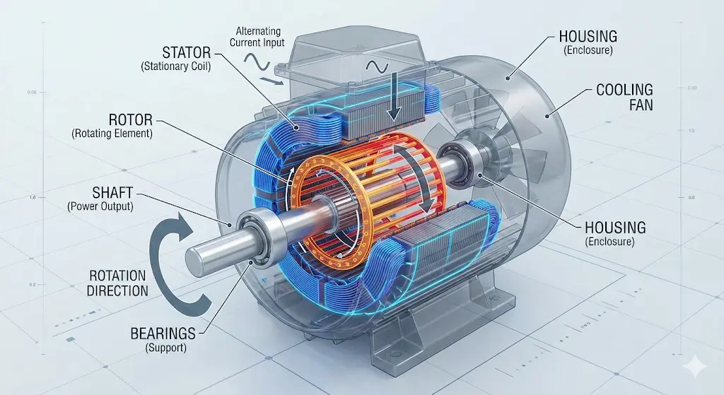
II.3. BY TYPE OF TRACTION → ELECTRIC
FUNDAMENTAL CHARACTERISTICS OF THE ELECTRIC TRACTION SYSTEM
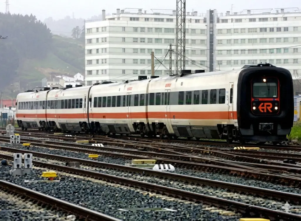
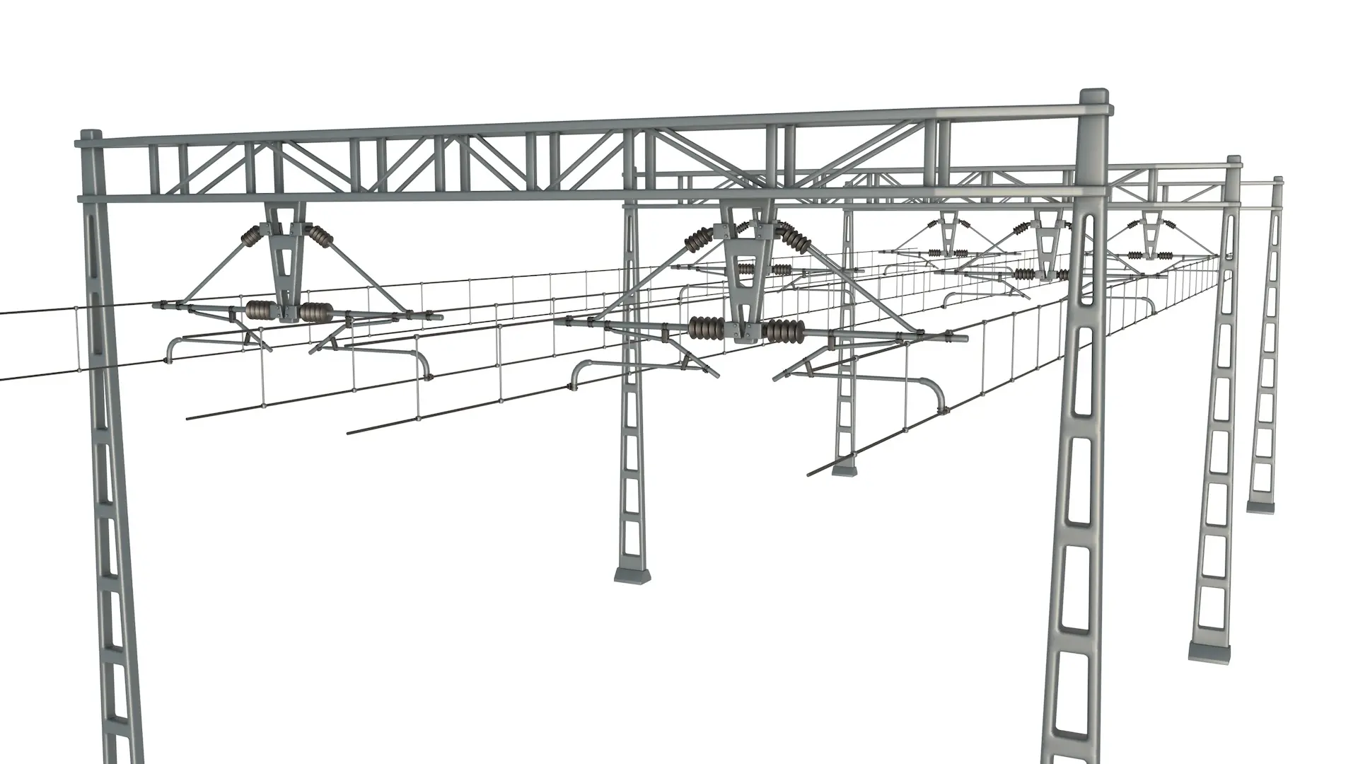
Electric propulsion currently constitutes the most advanced and sustainable solution for passenger railway transport in high-performance systems. It is a deeply developed technology that has undergone continuous evolution in recent decades.
The electric traction system is characterized by its dependence on an external power source, which must be supplied through dedicated infrastructure. This source can take several forms:
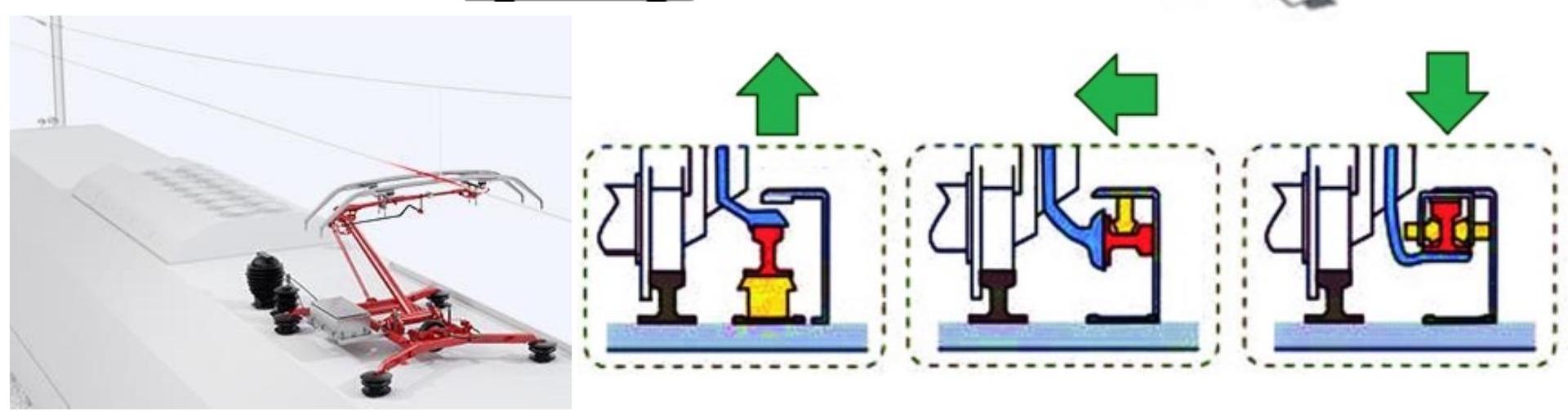
- Overhead catenaries supplying voltages in direct current (DC) from 750 V to 3000 V, or in alternating current (AC) up to 25 kV
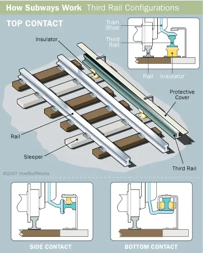
- Third rail located along the track supplying voltages typically between 600 and 750 V in direct current
The main advantages of the electric system include: significantly higher energy efficiency than diesel propulsion, translating into lower long-term operational costs; absence of local pollutant emissions at the vehicle’s point of use; and superior acceleration and control capabilities.
However, it also presents important disadvantages: very high initial cost associated with infrastructure electrification; visual and landscape pollution generated by the installation of catenaries and associated structures; and dependence on the availability of electrical energy sources.
CLASSIFICATION OF ELECTRIC SYSTEMS BY CURRENT TYPE
The nature of the current system used constitutes a fundamental classification:
- ELECTRIC TRACTION IN DIRECT CURRENT (DC): Uses constant direct voltage
- ELECTRIC TRACTION IN ALTERNATING CURRENT (AC): Uses alternating voltage
ELECTRIC MULTIPLE UNITS (EMU)
Modern electric compositions frequently employ the multiple unit configuration, where motive capacity is distributed among several vehicles of the composition.
- MULTI-SYSTEM ELECTRIC TRACTION: Some modern vehicles are equipped to operate under multiple electrical supply systems, allowing flexible operation on heterogeneous railway networks
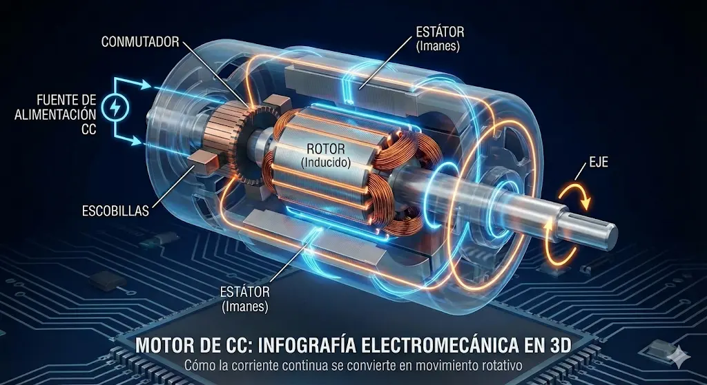
II.3.1. COMPARISON BETWEEN DC AND AC ELECTRIC TRACTION
The historical evolution of the railway electric traction system reflects advances in electric motor control technology:
Early 20th Century Period: During the early years of electric railway development, there was a clear preference for direct current motors due to the inherent technological limitations of alternating current systems. DC motors provided adequate torque characteristics and were reasonably simple to control using techniques available at that time.
Evolution in the 1980s: With the advancement of power electronics, particularly the development of more advanced power semiconductors, alternating current motors began to configure themselves as a serious and viable alternative to DC motors. Subsequent technological advances in electronic converters have consolidated the current prevalence of alternating current electric traction.
Advantages of AC motors over DC:
- AC motors are structurally simpler to build than DC motors for equivalent power
- AC motors are significantly lighter than their DC counterparts of similar power
- AC motors are more robust and have lower maintenance requirements compared to DC motors
- Modern power electronics allow efficient control of adhesion and traction parameters in AC systems
II.4. BY TYPE OF TRACTION → HYDROGEN
Chapter III. Hydrogen propulsion: emerging technology for the railway future
Hydrogen propulsion technology represents one of the most promising frontiers in the search for sustainable and low-emission transport solutions for the railway sector. This system emerges as a viable alternative to traditional fossil fuel systems.
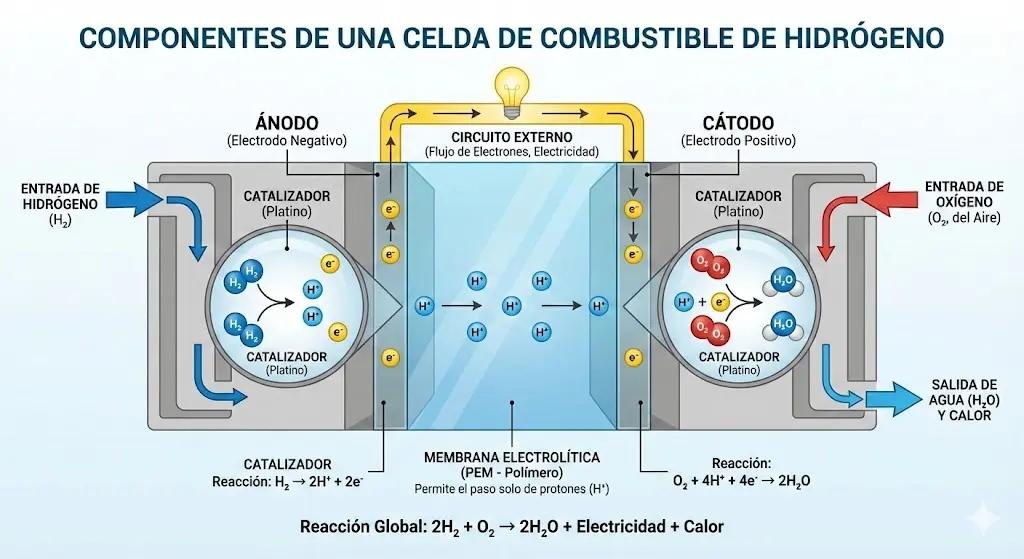
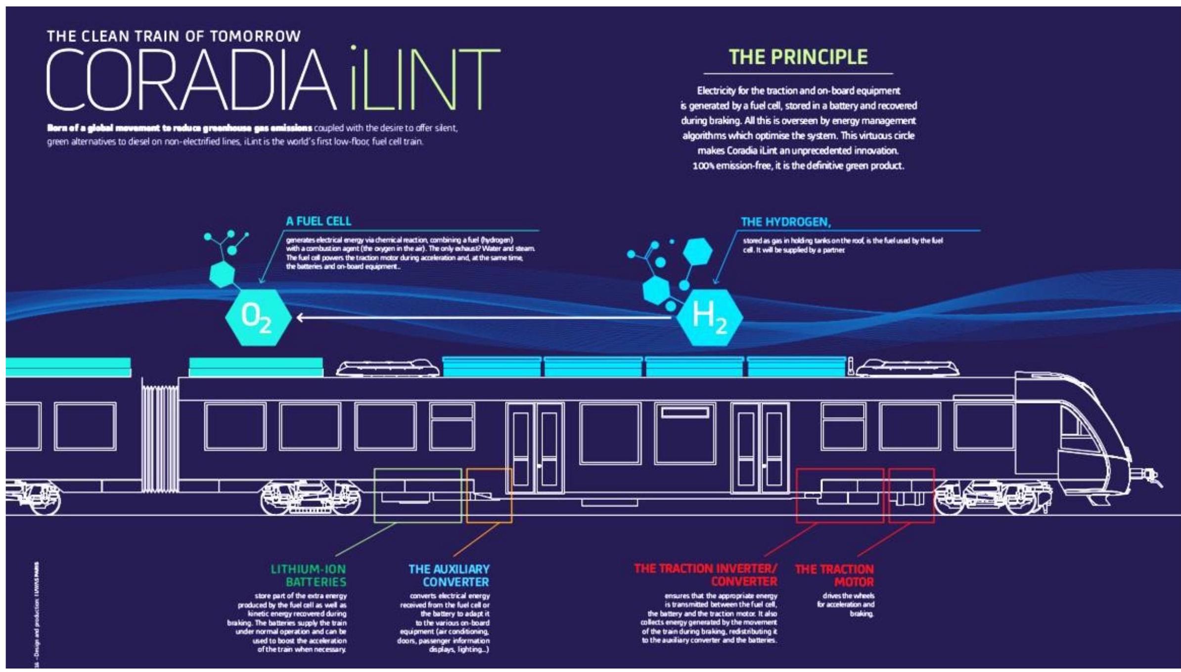
FUNDAMENTAL OPERATING PRINCIPLES
Hydrogen in a gaseous state is subjected to a controlled chemical reaction with environmental oxygen within specialized components called fuel cells. This controlled reaction generates water vapor as a residual product while releasing electrical energy. The electrical energy produced is used in an integrated manner to:
- Charge energy storage systems based on lithium-ion batteries
- Drive traction systems using electric motors
The entire system is managed by electronic control units that optimize energy flow and vehicle performance according to required operational profiles.
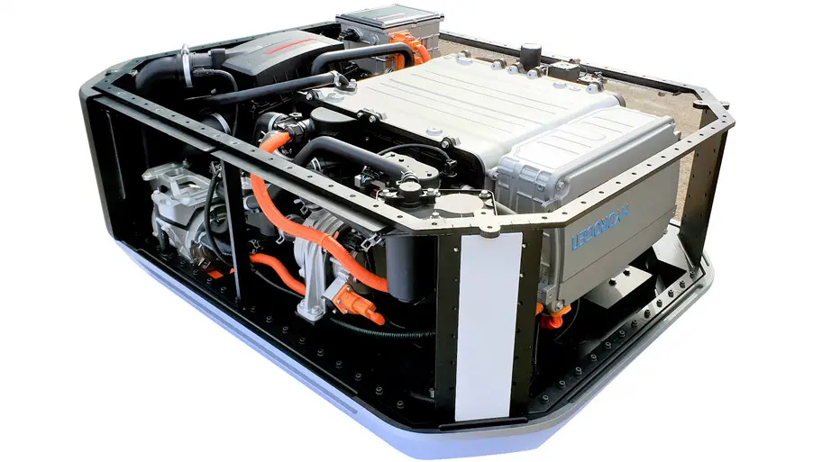
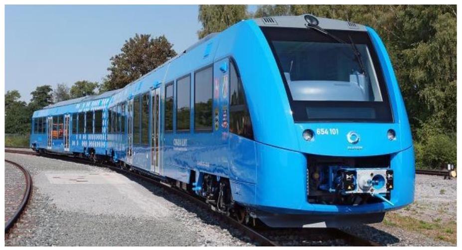
III.1. COMMERCIAL APPLICATIONS AND PROTOTYPES: ALSTOM CORADIA iLINT
FIRST COMMERCIAL HYDROGEN TRAIN (2018)
The company Alstom presented the first operationally viable hydrogen-powered passenger train, named Coradia iLINT, representing an important milestone in the commercialization of this emerging technology. This pioneering prototype established an important operational precedent for the industry.
Technical configuration of the Coradia iLINT:
The vehicle consists of a composition of two mechanically joined cars, equipped with the following specialized components:
- Storage system: 99 kilograms of compressed hydrogen at a pressure of 350 bar
- Power generation system: 200 kW nominal power in fuel cells
- Auxiliary energy storage system: 225 kW capacity in lithium-ion batteries
- Passenger capacity: 138 seated passengers plus 190 standing passengers (328 total people)
- Operational range: 600 kilometers of travel
- Refueling time: 15 minutes
- Maximum operational speed: 140 km/h
DISADVANTAGES AND LIMITATIONS OF THE HYDROGEN PROPULSION SYSTEM
Despite the promising potential of hydrogen technology, there are significant limitations that have slowed its massive adoption in railway applications:
Economic challenges:
- The cost of hydrogen production is currently very high compared to conventional fuels
- Hydrogen storage and distribution costs are considerably high due to its voluminous nature and the complex infrastructure required
- After production, hydrogen requires specialized handling and storage procedures that translate into significant operational costs
Infrastructure challenges:
- The cost of implementing hydrogen refueling stations is very high
- There is currently very little infrastructure available to deliver hydrogen to consumption points (railway depots)
- Implementing a hydrogen infrastructure network would require massive capital investments
- Safety challenges:
- Hydrogen has characteristics that make its detection difficult: it is colorless and odorless, which significantly hinders leak identification
- Hydrogen is highly flammable, presenting significant risks in case of accidents or inadvertent leaks
- Very sophisticated safety systems and rigorous operational procedures are required
Environmental and resource challenges:
- Converting methane into hydrogen via reforming is a process that consumes significant amounts of water
- In contexts where water is a scarce resource, this technology can exacerbate pressures on water availability
Chapter IV. Railway Composition Architecture
The architecture of a train, understood as the way in which its structural and functional components are organized and connected, constitutes a fundamental design parameter that determines the operational performance and maintenance characteristics of the complete system. Through the evolution of railway transport, several different architectural configurations have emerged, each with specific advantages and limitations.
FUNDAMENTAL CLASSIFICATION BY ARCHITECTURAL CONFIGURATION
According to their architecture, trains can be classified into several clearly differentiated groups:
-
Conventional or towed trains: This configuration consists of one or more motive units (locomotives) that exert traction on a set of towed vehicles (coaches or wagons). The main advantage of this configuration lies in operational flexibility, as the composition can be modified by adding or removing coaches or wagons according to the specific operational needs of each service.
-
Self-propelled trains: In this configuration, the train is formed by one or several self-propelled systems, each incorporating its own traction system and passenger spaces. It is important to note that when referring to “self-propelled”, multiple types of systems are included, from individual railcars (a single vehicle with its own traction) to more complex formations of multiple units. This semantic distinction is important: not all self-propelled trains are railcars, but the railcar is a specific class of self-propelled train consisting of a single vehicle.
SUBCATEGORIZATION OF SELF-PROPELLED TRAINS
With the proliferation of self-propelled systems, the traditional distinction between motive power and towed stock has become progressively less clear. Modern self-propelled trains are subdivided into two main categories according to the distribution of their motive systems:
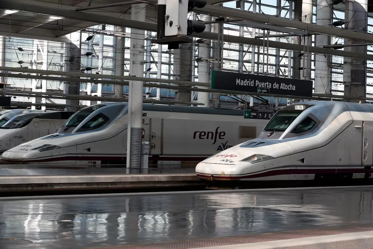
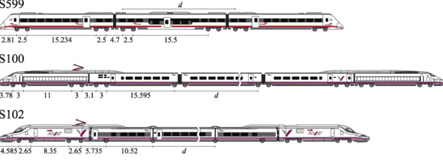
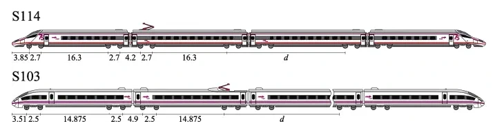
a) Concentrated traction trains: In these systems, all motive capacity is concentrated in one or more locomotives (also called power heads) that are permanently coupled to the composition. Although the motive vehicles are permanently integrated, they retain their identity as separate components. Representative examples of this configuration include some compositions of the Spanish High Speed (AVE) system and the Euromed train.
b) Distributed traction trains:
In this alternative architecture, traction systems are not concentrated in specific locomotives, but are distributed across several vehicles of the composition called motor cars. These motor cars are vehicles that simultaneously house passengers or cargo and provide motive capacity. Representative examples include the Series 103, the Civia train, the Alaris, and other modern regional transport systems.
DESIGN CONSIDERATIONS FOR HIGH SPEED
An important technical aspect in the evolution of railway architecture is that it has been observed experimentally that for operating speeds above 300 km/h, concentrated traction trains experience dynamic overload phenomena that do not favor the maintenance of track geometric quality. This consideration is particularly critical in high-speed systems where infrastructure geometric precision is a critical factor for safety and comfort. This observation has significantly influenced architectural decisions for new long-distance transport systems.
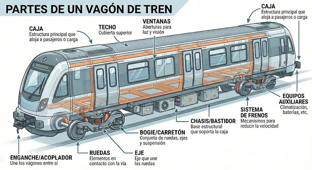
Chapter V. Fundamental Components of Rolling Stock
Any railway vehicle, whether a locomotive, a passenger coach, or a freight wagon, is made up of a series of structural and functional elements that interact in a coordinated manner. Understanding these components is essential to understand the operation and performance of the complete system.
BODY OR CARBODY
The body constitutes the main structural element of any railway vehicle, functioning simultaneously as a skeleton or support frame and as a functional space for operation. In its structural function, the body provides the necessary rigidity to resist loads and stresses derived from operation. In its accommodation function, it constitutes the space where all specialized equipment and systems are housed.
In locomotives and self-propelled rolling stock, the body houses a series of specialized equipment that varies according to the type and function of the vehicle. Among these pieces of equipment are: transformers and reactors for electrical systems; pneumatic compressors for brake and auxiliary systems; dynamic brake resistors; energy storage batteries; fans for system cooling; and pantographs for energy capture from catenaries.
The body also constitutes the space where passengers are located in passenger coaches, or where merchandise is housed in freight wagons. Additionally, in motive stock, the body incorporates the driving cab from where the operation of the vehicle is controlled and supervised.
BOGIE
The bogie constitutes the dynamic support structure that bears the weight of the body and transmits it to the ground through the rolling elements. The body rests on the bogies through specialized connection and suspension systems. In these connections between axles and bogie, axle boxes are used that allow load transmission while enabling controlled relative movements.
The bogie represents much more than a simple structural support. Its structure houses components critical to the vehicle’s dynamic operation: traction motors (in motorized vehicles); gears that transmit power from motors to axles; specialized brake mechanisms that dissipate kinetic energy; and suspension systems that isolate the body from track irregularities.
AXLES AND WHEELS
The axles and wheels constitute the final elements of the force transmission chain, being the only vehicle components that come into direct physical contact with the railway track. These elements are critical for operational safety and have very rigorous technical specifications.
Axles are structural components that house the rolling systems (wheels) and transmit longitudinal forces (traction and braking) and lateral forces. Wheels are the circular elements that roll on the rails, transferring the vehicle’s weight and allowing controlled movement on the track.
Parts
Chapter VI. Gauge Specifications: Dimensional Envelopes of Railway Vehicles
The concept of gauge constitutes one of the most critical parameters in railway engineering, determining the compatibility between rolling stock and existing infrastructure, as well as operational safety. Gauge specifications are rigorously standardized through mandatory technical regulations.
REGULATORY FRAMEWORK: ORDER FOM/1630/2015
In the Spanish railway context, Order FOM/1630/2015 of July 14, approving the Railway Gauge Instruction, establishes the technical standards that all railway vehicles must meet. This normative instruction performs critical functions in two complementary areas:
-
Definition of gauges for rolling stock: Establishes the maximum dimensional envelopes that vehicles can occupy during circulation. These rolling stock gauges are applicable to the definition of constructive profiles for any type of motive or towed material, both for new construction and for subsequently conditioned vehicles.
-
Definition of obstacle implementation gauges: Specifies dimensional limitations for the placement of elements and infrastructure close to the railway track. These implementation gauges are applicable in new railway line construction projects, as well as in existing line conditioning projects.
SCOPE OF APPLICATION
The instruction is applicable to railway lines integrated into the general interest railway network, regardless of the track gauge used: Iberian gauge (1668 mm), European standard gauge (1435 mm), or metric gauge (1000 mm).
VI.1. Dynamic Gauge Concept: Complete Dimensional Envelope
TECHNICAL DEFINITION
The dynamic gauge constitutes the geometric envelope that defines the maximum space a railway vehicle can occupy during all phases of its operation. This envelope is not simply the static geometric projection of the vehicle, but includes all possible displacements that vehicle points can experience due to multiple causes. The envelope integrates both predictable (quasi-static) displacements derived from phenomena such as centrifugal force in curves, track cant effects, and predictable oscillations due to infrastructure irregularities, as well as random displacements (random oscillations of circulating material) resulting from unpredictable track-vehicle interaction and possible lateral, elastic, or permanent movements of the track superstructure.
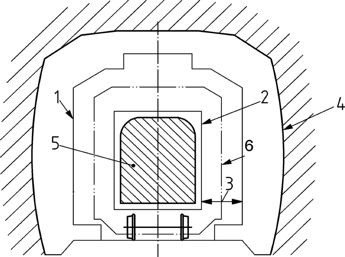
(1) Obstacle implementation gauge (2) Maximum constructive profile of the material (3) Sum of vehicle movements and infrastructure interaction phenomena (4) Infrastructure (5) Vehicle (6) Reference contour
| GAUGE TYPES | TRACK GAUGE (mm) | ||
|---|---|---|---|
| 1668 | 1435 | 1000 | |
| NEW | GEA16 | GA | GED10 |
| GEB16 | GB | GEE10 | |
| GEC16 | GC | ||
| HISTORICAL | GHE16 | GEC14 | |
| GC14 |
COMPONENTS OF THE DYNAMIC GAUGE ENVELOPE
The rigorous construction of the dynamic gauge requires considering several progressive components that integrate cumulatively:
- Maximum constructive profile of the material: The dimensional envelope of the vehicle in its resting form
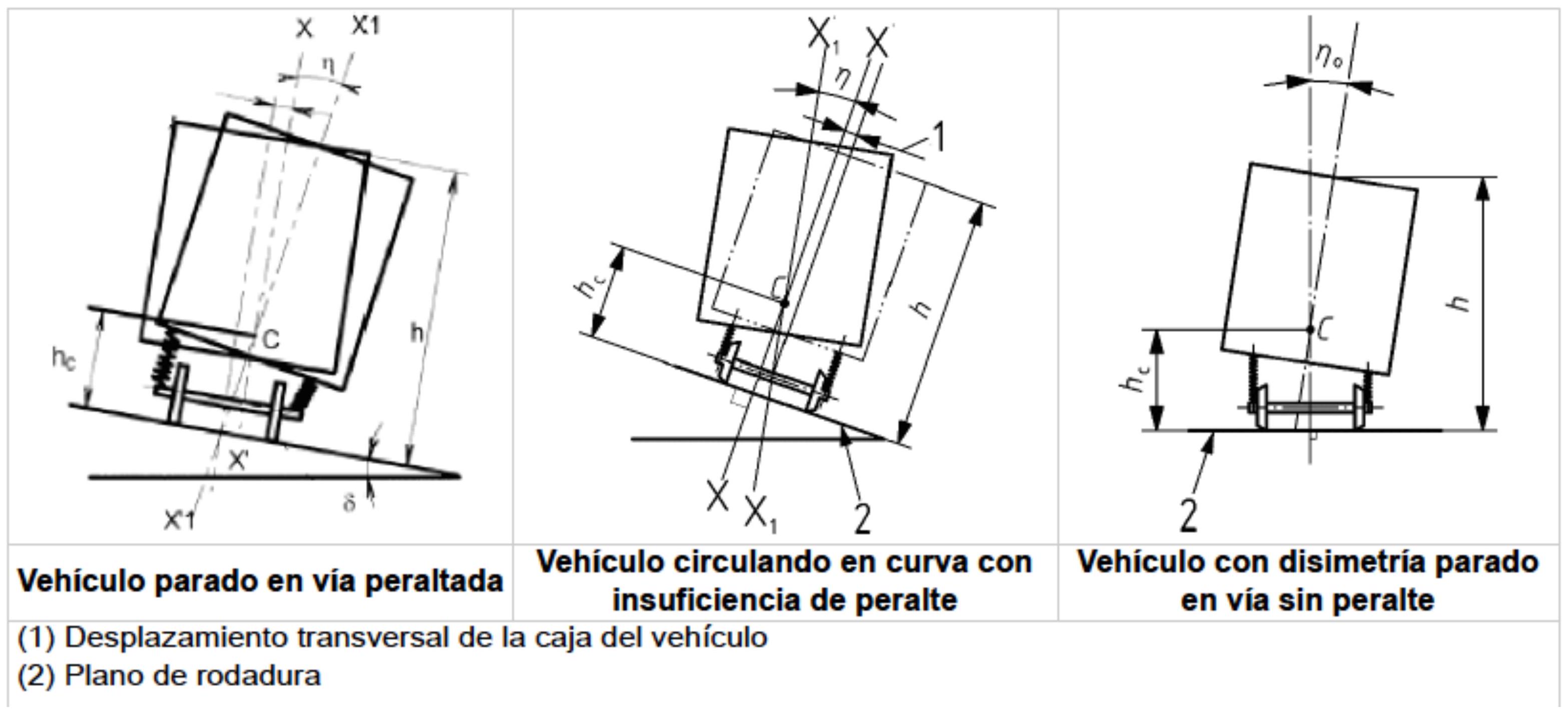
- Quasi-static displacements: Considering variations in load dissymmetry when reference values (\(I_0\) or \(D_0\)) are exceeded, particularly when maximum values based on cant (\(s > s_0\)) and center of gravity height (\(h_c > h_{co}\)) are exceeded
- Reduction margins: Application of reduction factors (\(E_i\) or \(E_a\)) considering optimization criteria
- Reference contour: The kinematic envelope integrating the constructive profile and quasi-static displacements
- Lateral random displacements: Considering unpredictable movements derived from track-vehicle interaction (\(M_1 + M_2\))
- Complementary safety margins: Additional lateral safety spaces (\(M_{3b}\)) to ensure correct functioning of adjacent systems
- Nominal obstacle implementation gauge: The final limit defining where obstacles and infrastructure elements can be placed
TECHNICAL REFERENCES OF COMPONENT ELEMENTS
The regulatory specification uses a series of parameters and technical references to describe specific components of the gauge envelope:
- \(I_0\) or \(D_0\): Load dissymmetry reference values
- \((I_{\text{máx}} - I_0)\) or \((D_{\text{máx}} - D_0)\): Dissymmetry excesses over reference values, applicable when cant thresholds (\(s > s_0\)) and center of gravity height (\(h_c > h_{co}\)) are exceeded
- \(E_i\) or \(E_a\): Reduction factors applied to the envelope
- S: Envelope protrusion
- \(D\): Vehicle lateral displacement
- Reference contour plus protrusions: Envelope integrating the basic reference contour and localized protrusions
- Quasi-static displacement: For reference parameters \(s = s_0\) and \(h_c = h_{co}\)
- Kinematic envelope: Geometric locus of the material considered with kinematic freedom of movement
- Lateral random displacements: \(M_1 + M_2\) representing unpredictable movements
- Limit obstacle implementation gauge: Initial maximum limit
- Complementary lateral margins: \(M_{3b}\) providing additional safety spaces
- Nominal obstacle implementation gauge: Final operational limit
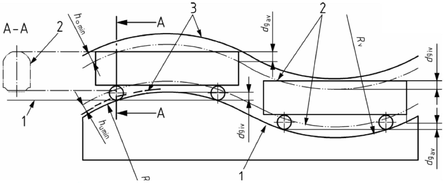
HEIGHT PARAMETERS IN VERTICAL CURVES
In the context of complex altimetric profiles with curved vertical transitions, specific height parameters are defined:
(1) Rolling plane: Contact surface between wheels and rails (2) Reference contour: Vehicle reference envelope (3) Limit position of obstacles: Prohibited zone for infrastructure
\(h_{\text{umin}}\): Minimum height considered for vertical displacement of rolling stock below the reference contour when circulating in concave vertical transitions. This parameter defines how much the vehicle can “sink” \(h_{\text{omin}}\): Minimum height considered for vertical displacement of rolling stock above the reference contour when circulating in convex vertical transitions. This parameter defines how much the vehicle can “rise” \(R_{\text{vmin}}\): Minimum curvature radius of the vertical transition that must be considered in infrastructure design
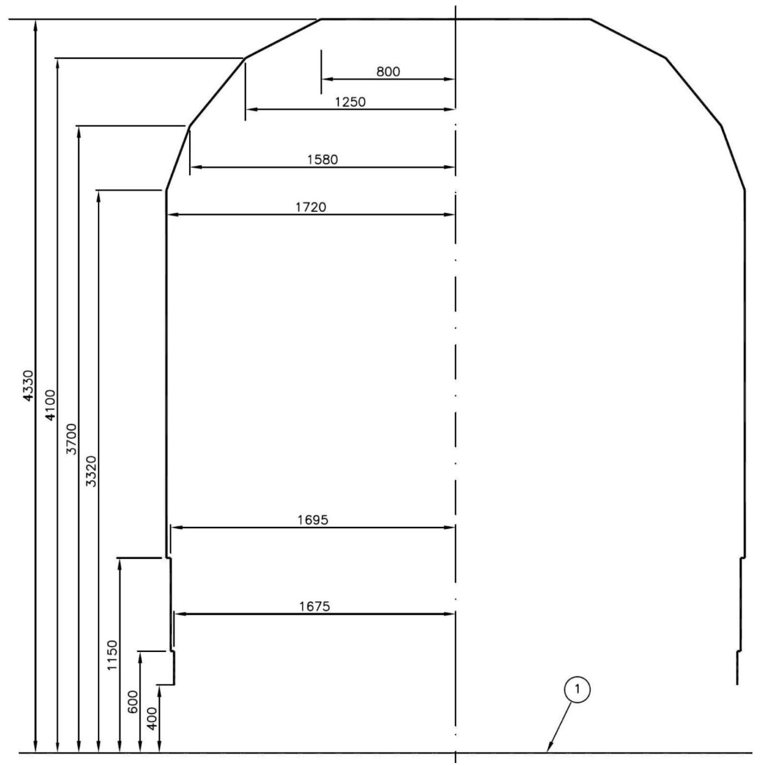
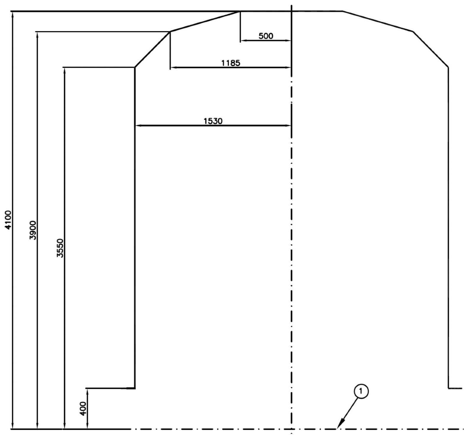
EXAMPLES OF SPANISH STANDARDIZED GAUGES
In the context of Spanish railway regulations, several specific gauges are defined according to track gauge and vehicle nature (new or historical):
GEA16 Gauge (Iberian gauge 1668mm, new vehicles of larger size):
GEE10 Gauge (Metric gauge 1000mm, new vehicles):
Chapter VII. Lower Part Gauge Specifications: Vehicle Lower Envelopes
Gauge specifications for the lower parts of the vehicle constitute a specialized technical aspect requiring particular considerations. These envelopes define the dimensional limits of components and systems located in the lower zones of the vehicle that could come into contact with obstacles, track elements, or adjacent infrastructure.
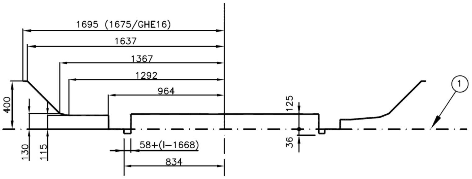
GEI1 GAUGE
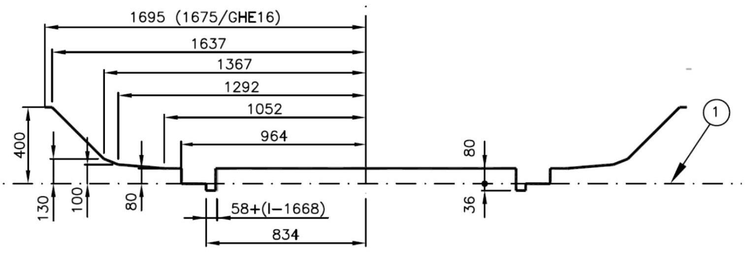
GEI2 GAUGE
| Line Type | Track Gauge | |
|---|---|---|
| 1435 mm | 1668 mm | |
| Suitable for Rolling Highway transport(1) | GI3 | GEI3 |
| Not suitable for Rolling Highway transport | GI2 | GEI2 |
Gauge specifications for lower parts vary depending on the planned service type. Lines designed to be compatible with Rolling Highway systems (allowing transport of road vehicles on railway supports) have different dimensional requirements compared to conventional lines not incorporating this operational capability.
Chapter VIII. Axle, Wheel and Bogie Systems: Running Gear Configurations
The running gear system of a railway vehicle defines how loads are transmitted and distributed to the railway infrastructure. different running gear configurations have significant implications for dynamic behavior, load capacity, and vehicle stability.
RUNNING GEAR CONFIGURATIONS IN COACHES
In passenger vehicles, there are two fundamental configurations of axle and bogie systems:
Single axle coaches: In this configuration, the vehicle rests directly on single axles without an intermediate bogie. This is a simpler and more economical configuration, but with limitations in speed and comfort.
Bogie coaches: In this more modern and conventional configuration, the vehicle rests on two bogies, typically with two axles each. This configuration provides better dynamic behavior, higher speed capacity, and better passenger comfort.
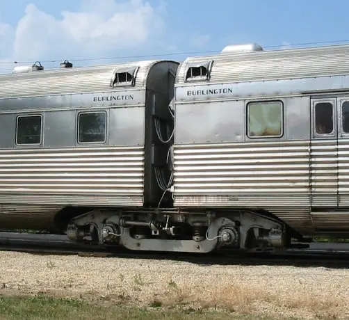
ARTICULATED VS. NON-ARTICULATED CONFIGURATIONS
Beyond the type of running gear, coaches can be classified according to their longitudinal arrangement:
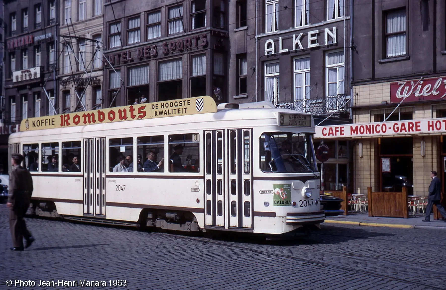
Non-articulated coaches: Independent vehicles that are mechanically joined to other vehicles via standard coupling systems. Each coach has its own complete independent structure.
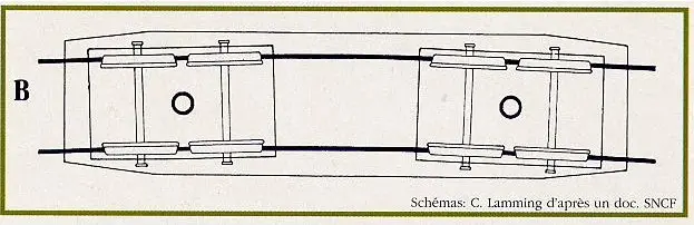
Articulated coaches: In this special configuration, two coaches share a common bogie. The central bogie acts as a support element for both vehicles, allowing for weight reduction, improved spatial efficiency, and optimization of the composition’s dynamics.
VIII.1. Detailed Analysis of Axles, Wheels and Running Gear Configurations
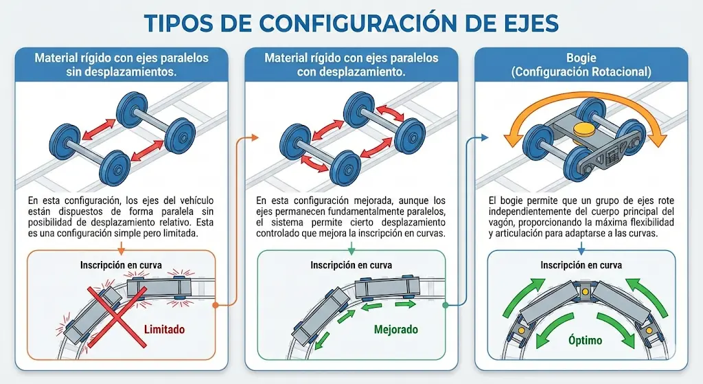
AXLE CONFIGURATION TYPES
 Rigid material with parallel axles without displacement.
In this configuration, the vehicle’s axles are arranged in parallel without the possibility of relative displacement. This is a simple but limited configuration.
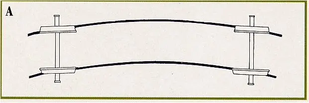
 Rigid material with parallel axles with displacement.
In this improved configuration, although the axles remain fundamentally parallel, the system allows for certain controlled displacement which improves curve negotiation.
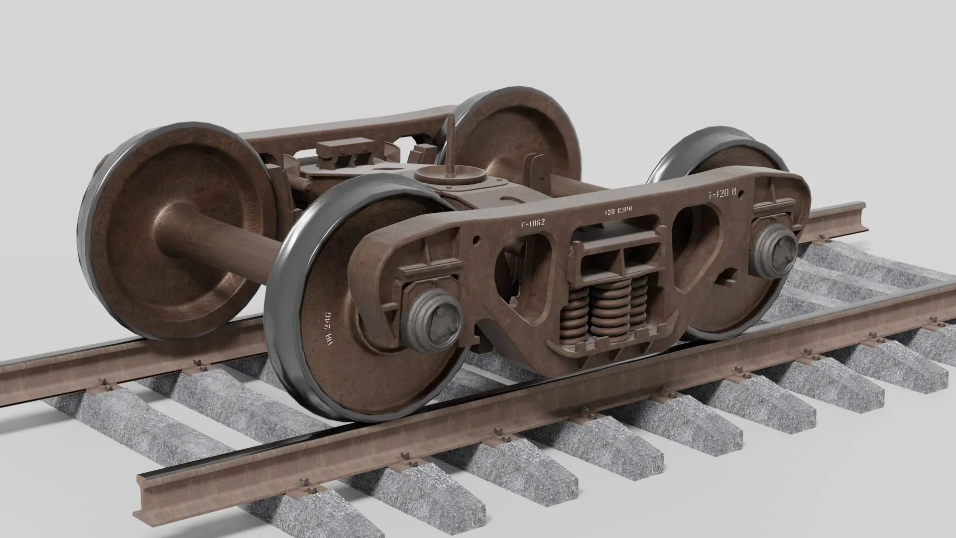
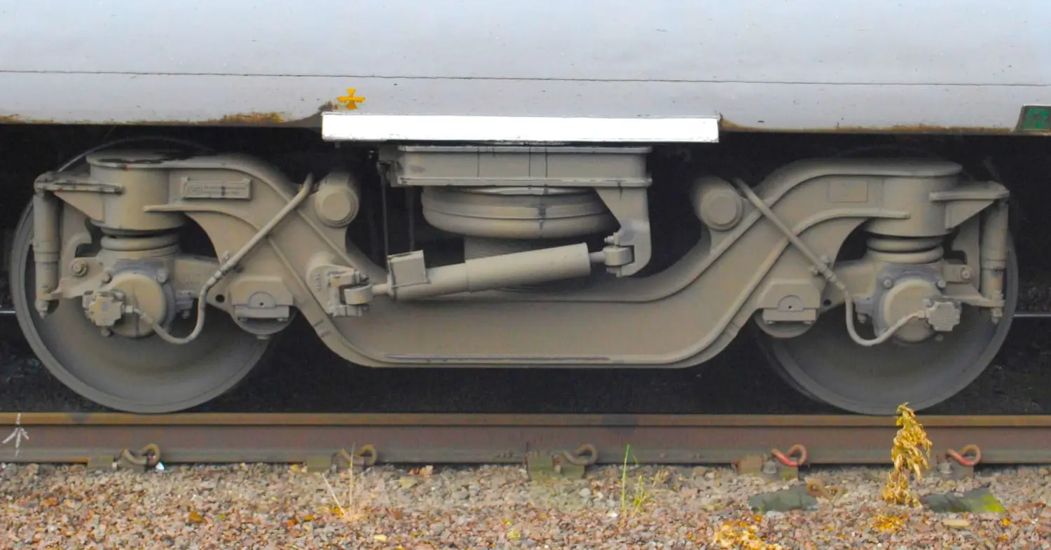
VIII.2. Structure and Components of the Bogie: Dynamic Support System
The bogie constitutes the fundamental element for the suspension and guidance of the railway vehicle. Its design and configuration largely determine dynamic behavior, maximum permitted speed, and operational comfort.
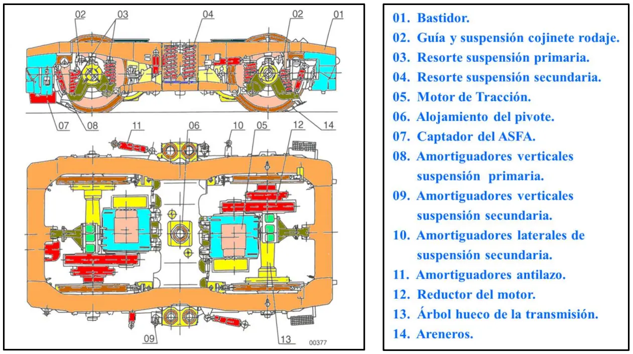
MAIN COMPONENTS OF THE BOGIE
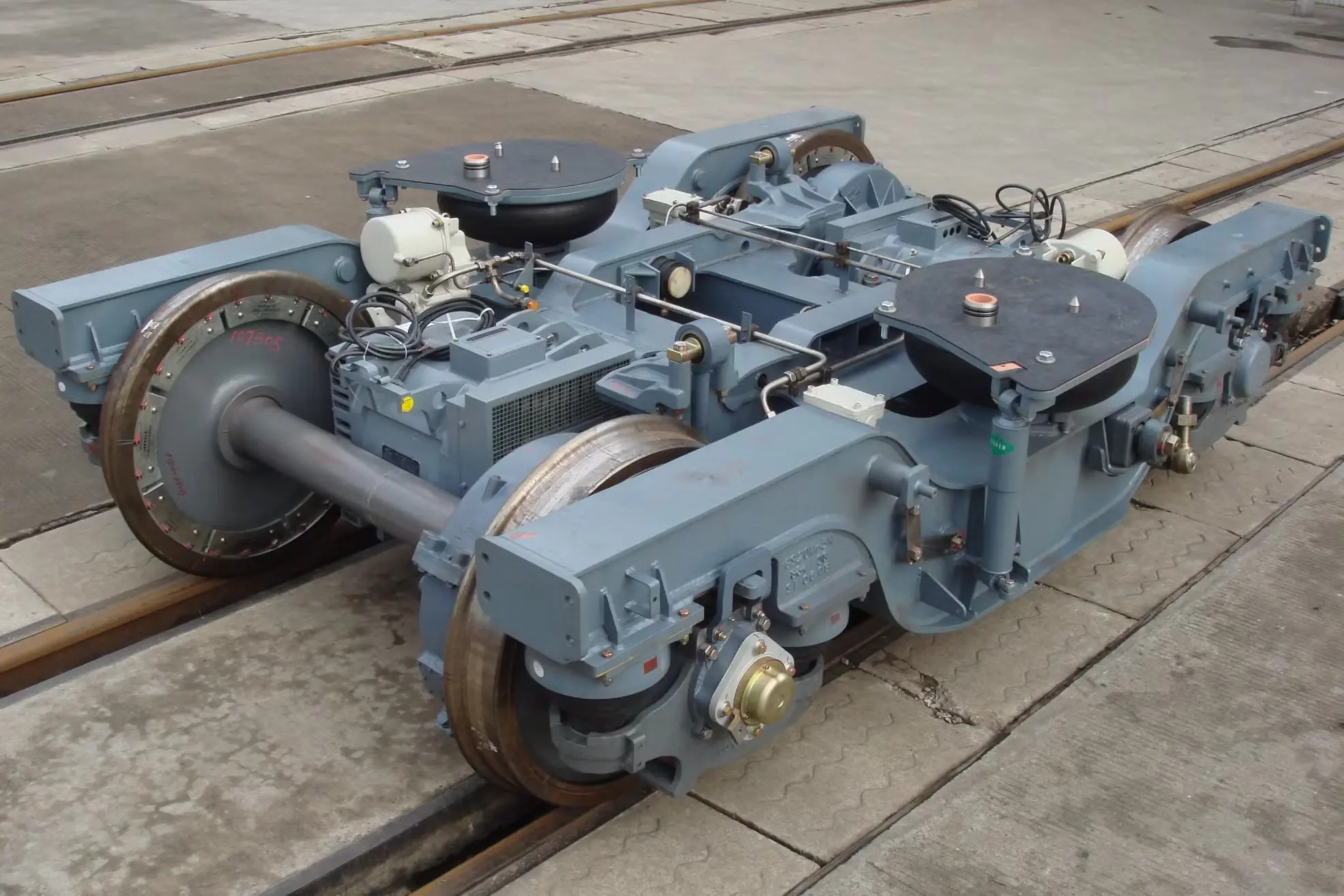
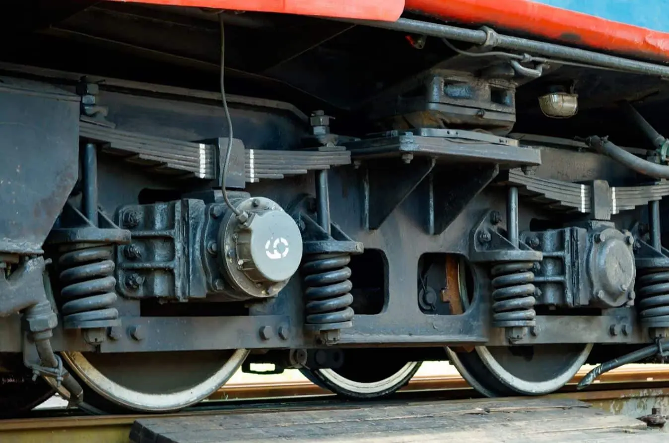
The modern bogie integrates multiple subsystems that work in a coordinated manner to provide support, control, and efficient traction. These components include the supporting structure, primary and secondary suspension systems, traction motors, speed reducers, and specialized brake mechanisms.
SHARED BOGIES: EFFICIENCY IN ARTICULATED COMPOSITIONS
In modern articulated compositions, particularly in systems like the Civia, the shared bogie configuration between carriages is used. This centralized bogie acts as a support element for two adjacent cars, which presents significant advantages in terms of weight reduction, spatial optimization, and improvement of the overall composition dynamics.
 Shared bogie
Chapter IX. Locomotives: Classification, Nomenclature and Axle Configurations
Locomotives constitute the fundamental traction vehicles in towed railway transport systems. Their classification and nomenclature are based on well-established criteria describing their mechanical configuration and operational characteristics.
UIC NOMENCLATURE SYSTEM FOR LOCOMOTIVES
The UIC (International Union of Railways) nomenclature system provides a standardized code describing the axle configuration of any railway locomotive. This nomenclature is universal and allows for quick identification of the structural characteristics of any railway vehicle.
Components of the UIC nomenclature:
-
Capital letters (A, B, C, etc.): Represent consecutive driving axles. Thus, ‘A’ indicates one driving axle, ‘B’ indicates two consecutive driving axles, ‘C’ indicates three consecutive driving axles, and so on.
-
Lowercase letter ‘o’: Used to indicate that driving axles are individually driven by separate traction motors. For example, Bo’ means that each driving axle has its own traction motor.
-
Numbers (1, 2, 3, etc.): Represent consecutive non-driving axles (guide axles). A low number indicates the quantity of axles without traction.
-
Apostrophe or prime (‘): Used to close the notation of axles that are mounted together on the same bogie, clearly delineating the bogie boundaries.
-
Parentheses: Employed to group all axles of the same bogie or car, allowing a clear reading of the vehicle’s structure.
-
Plus sign (+): Used to indicate locomotives with permanently coupled but mechanically separated vehicles (articulations).
-
Other suffixes: Added as needed to indicate special typology, speeds, steam systems, and other specialized characteristics.
MOST COMMON NOTATION IN MODERN LOCOMOTIVES: Bo’Bo’ AND Co’Co’
- Bo’Bo’: This is the most common configuration in modern electric and diesel locomotives of medium and medium-high speed. It consists of two identical bogies, each with two individually driven driving axles. This configuration provides an optimal balance between traction capacity, speed, and adaptability to different lines.
- Co’Co’: This configuration is used in heavy freight locomotives where maximum traction capacity is required. It consists of two identical bogies, each with three individually driven driving axles. This configuration provides maximum adhesion and hauling capacity, although at the cost of a lower maximum speed.
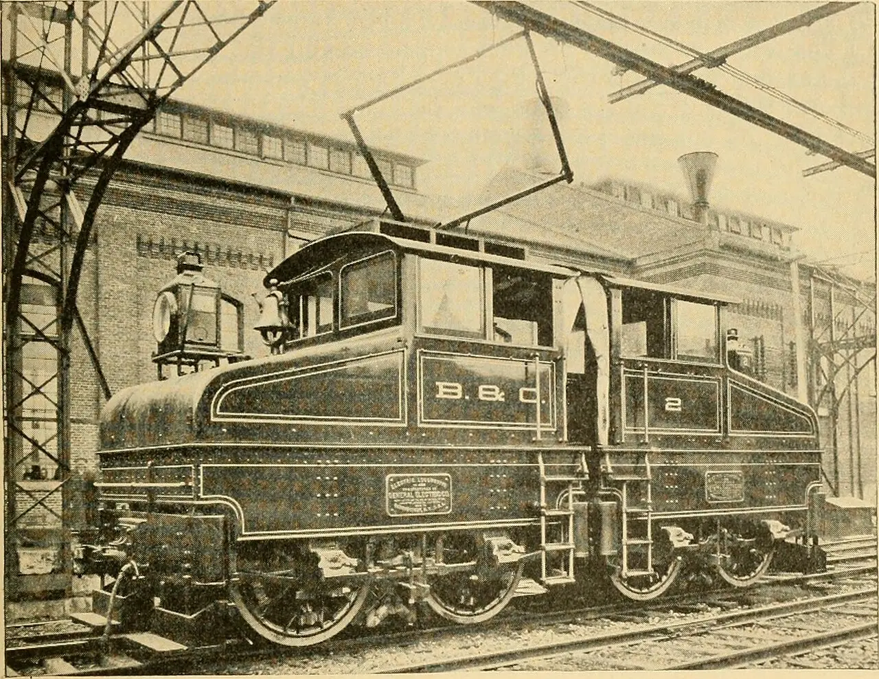
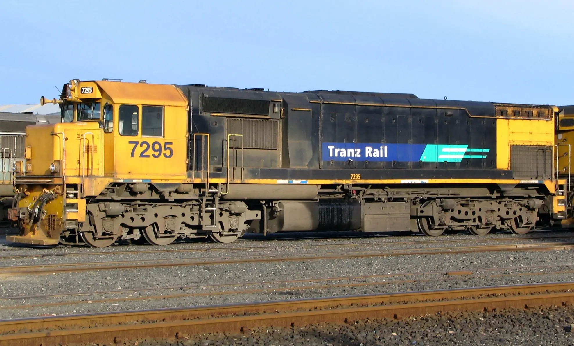 EXAMPLES OF UIC LOCOMOTIVE NOTATION IN USE
Various examples of UIC notation applied to real locomotives of different types and eras, showing the flexibility and clarity of the classification system.
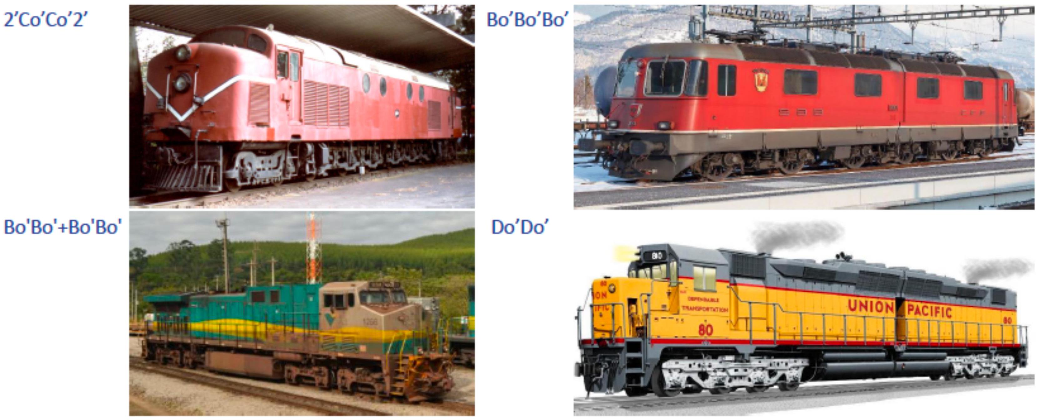
More examples of UIC configurations demonstrating the diversity of locomotive designs existing in the European and global railway network.
Chapter X. Railway Tractors (Shunters): Specialized Maneuvering Machines
Tractors constitute a special category of railway vehicles designed specifically for maneuvering and moving equipment in limited contexts such as yards, track sidings, and maintenance workshops. Although they are called “railway”, their nature is fundamentally different from conventional locomotives.
FUNCTIONAL CHARACTERISTICS OF TRACTORS
Tractors are machines, normally diesel-powered, used specifically for shunting in track sidings, repair workshops, and maintenance depots. Their design emphasizes traction force generation capacity rather than circulation speed. Available power is primarily oriented towards generating very high tractive effort, allowing the movement of very heavy loads or the maneuvering of complete compositions in restricted spaces.
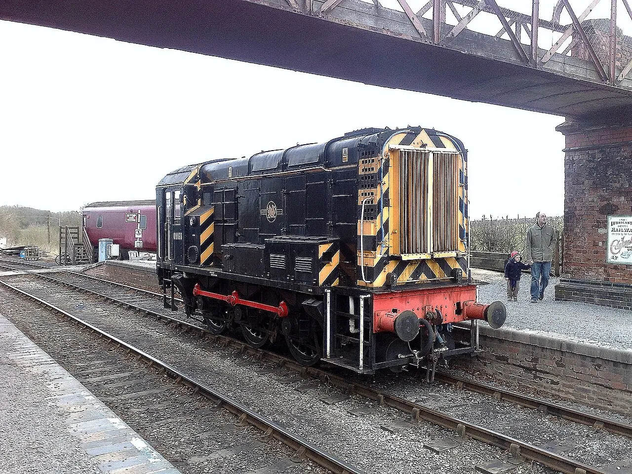
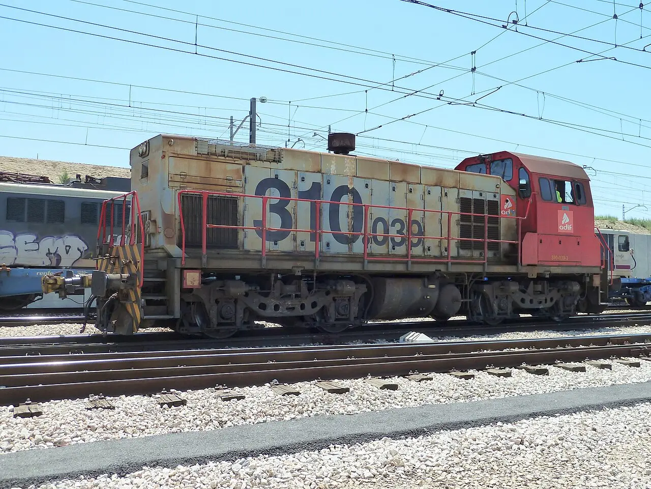
These specialized vehicles represent an important operational category allowing the critical function of moving and positioning railway equipment when not in service, thus facilitating maintenance, storage, and distribution operations within the railway infrastructure.
Chapter XI. Towed Stock: Classification and Constructive Characteristics
Towed stock constitutes the category of railway vehicles that do not possess their own traction capacity, but are propelled by motive units connected through coupling systems. This category is fundamental in conventional systems where one or more locomotives tow multiple vehicles.
DEFINITION AND FUNDAMENTAL CLASSIFICATION
The term “wagons” is specifically used for vehicles designed for freight transport (cargo), while the term “coaches” is used to refer to vehicles intended for the transport of people. Although these categories have distinct functions, they share similar structural characteristics in terms of general composition.
COMMON CONSTRUCTIVE STRUCTURE
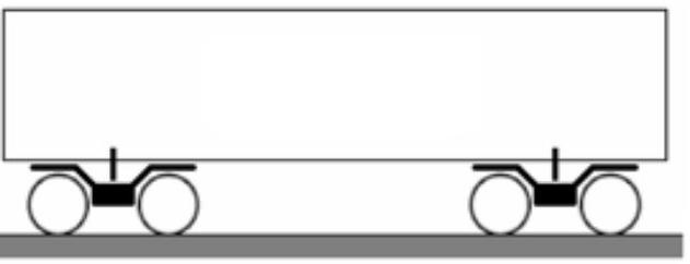
In both types of towed stock, the vehicle body or carbody is mounted on a supporting frame that acts as a support and load transmission structure. This frame, in turn, rests on the running gear, which consists of single axles or bogies, typically with two axles each. This modular structure allows the load capacity and operational characteristics of the vehicle to be adapted to the specific needs of each application.
Chapter XII. Freight: Typology, Characteristics and Compositions of Freight Wagons
Freight railway transport requires a very wide diversity of specialized vehicles, each designed to optimize the transport of specific cargo categories. The historical evolution of the wagon fleet reflects the progressive specialization of railway transport.
HISTORICAL EVOLUTION OF THE EUROPEAN WAGON FLEET
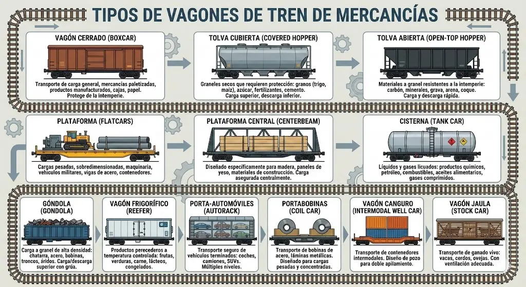
In the traditional European railway fleet, a significant variety of wagon types was found, each adapted to specific operational applications:
- Closed wagons for general cargo: Designed to protect merchandise from the weather, used for transport of multiple cargo types sensitive to climatic conditions
- Ventilated covered wagons for fresh fruit: Equipped with natural ventilation systems to maintain appropriate humidity and temperature conditions
- Ventilated covered wagons with tanks for dairy transport: Specifically designed to maintain refrigeration
- Refrigerated covered wagons: With active refrigeration systems for perishable products (meat, fish, fresh fruit)
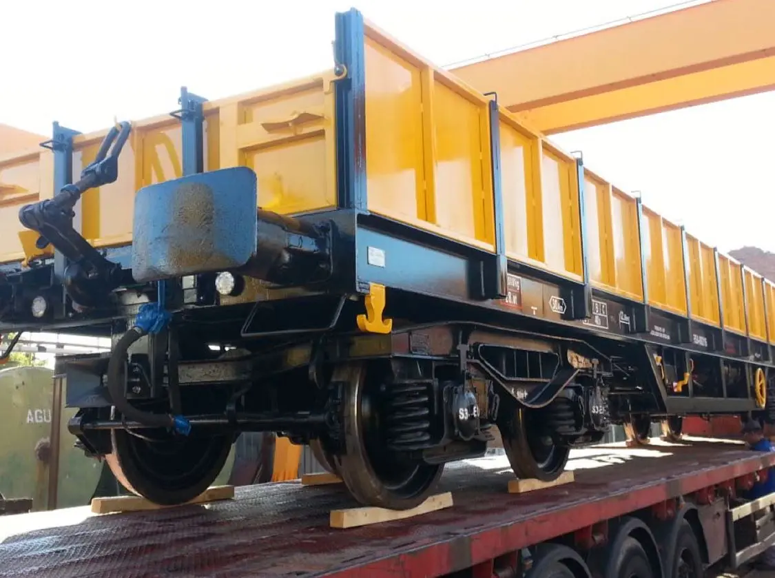
- Open wagons with low sides or flat wagons: Used for non-perishable cargo and easy lateral access (rails, sleepers, steel profiles, steel coils)
- Container flat wagons: Specialized in intermodal transport of standardized containers
- Mineral hoppers: Designed for loading and unloading bulk materials
- Multiple special configurations for specific applications
EVOLUTION TOWARDS HIGH CAPACITY WAGONS
The modern freight wagon represents a significant evolution comprising historical designs. The general trend has been towards higher load capacities to improve operational profitability:
- Historical wagons: Typically equipped with 2 single axles, with a length of approximately 10 meters
- Current wagons: Predominantly equipped with 4 axles grouped in 2 bogies, on which the supporting frame rests. If the maximum axle load is 20 tons, the net load capacity of a modern wagon can reach approximately 60 tons, compared to much lower capacities of historical wagons
- Length of modern wagons: Between 16 to 18 meters, reflecting the optimization of useful space
CLASSIFICATION OF WAGONS BY MULTIPLE CRITERIA
The diversity of modern wagons results from transport specialization according to multiple classification criteria:
- By running gear element: 2 single axles, 3 axles, or configurations with bogies
- By braking system type: Compressed air brake (more modern), or vacuum brake systems (more historical)
- By specialized commercial activity: Open, closed, flat, tank, container, hopper, refrigerated, and multiple special configurations
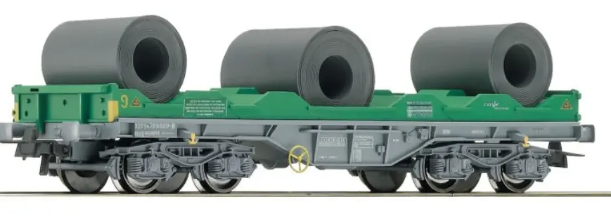
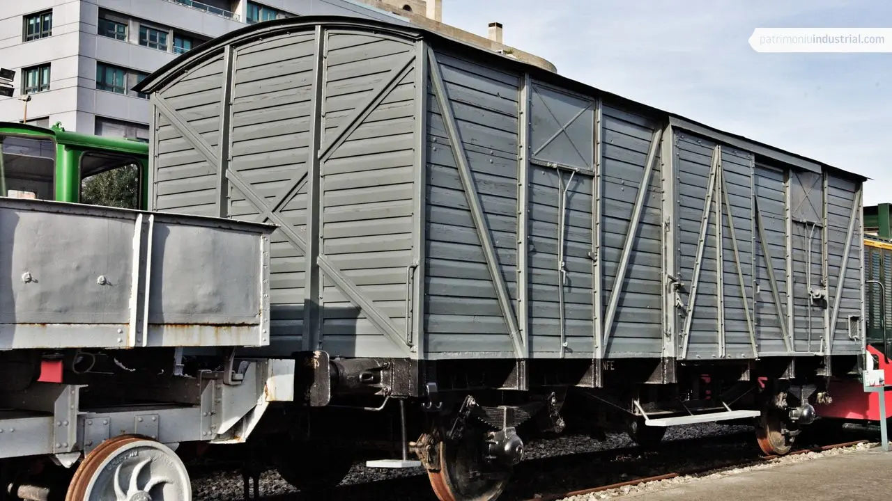
XII.1. Covered Freight Wagon: Cargo Protection Against Weather
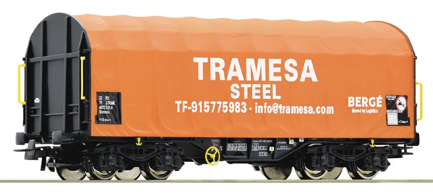
This type of wagon is specifically designed for the transport of heavy goods requiring protection against adverse weather conditions. The integral cover protects the cargo from rain, wind, and dust. Typical examples of transported goods include metal coils, aluminum bars, and other metallurgical products sensitive to oxidation and corrosion caused by humidity.
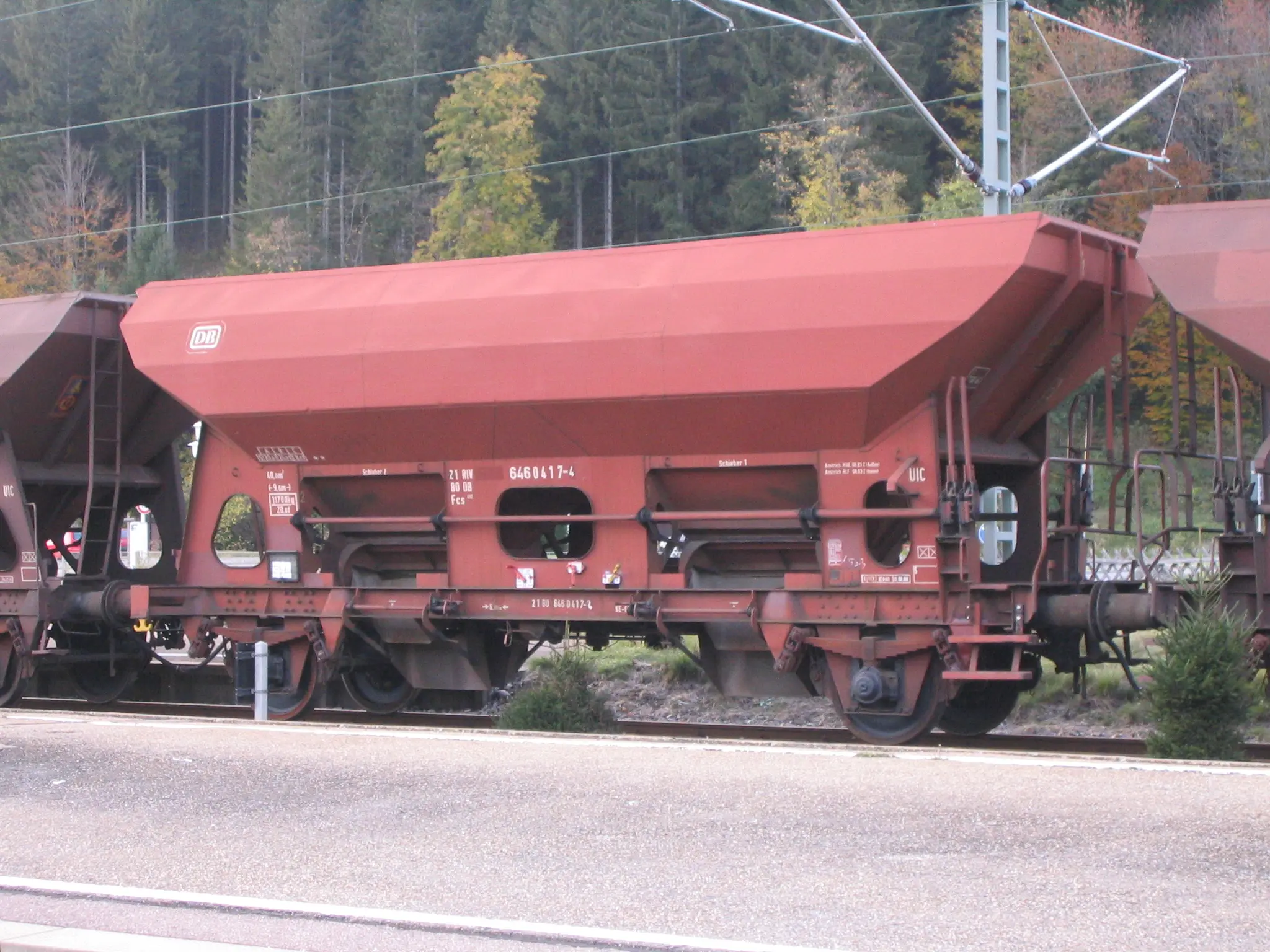
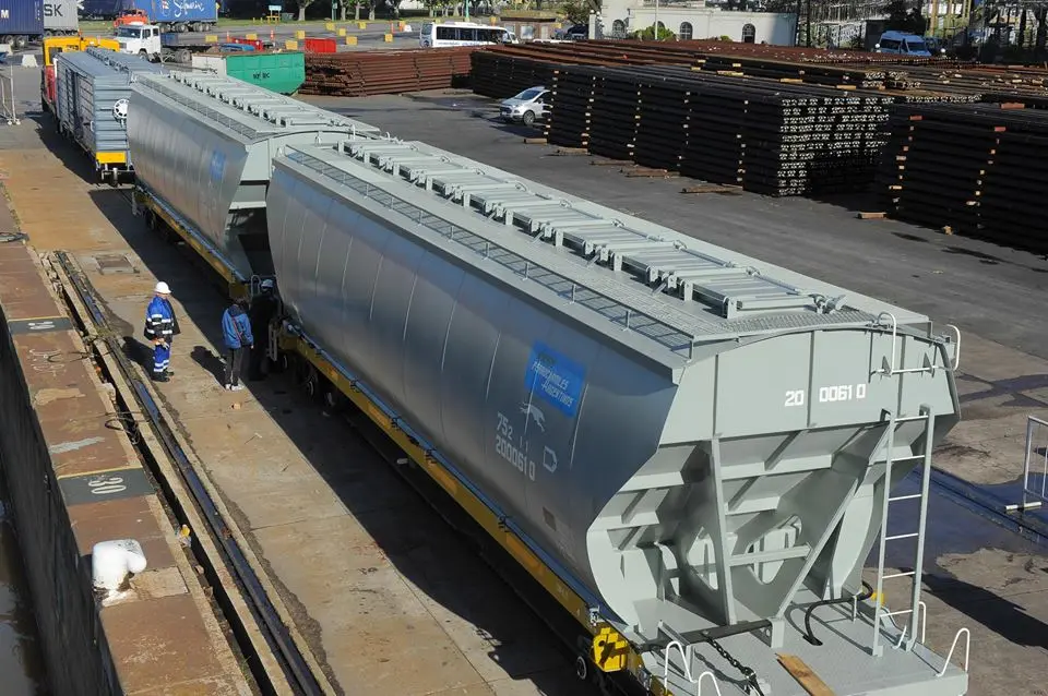
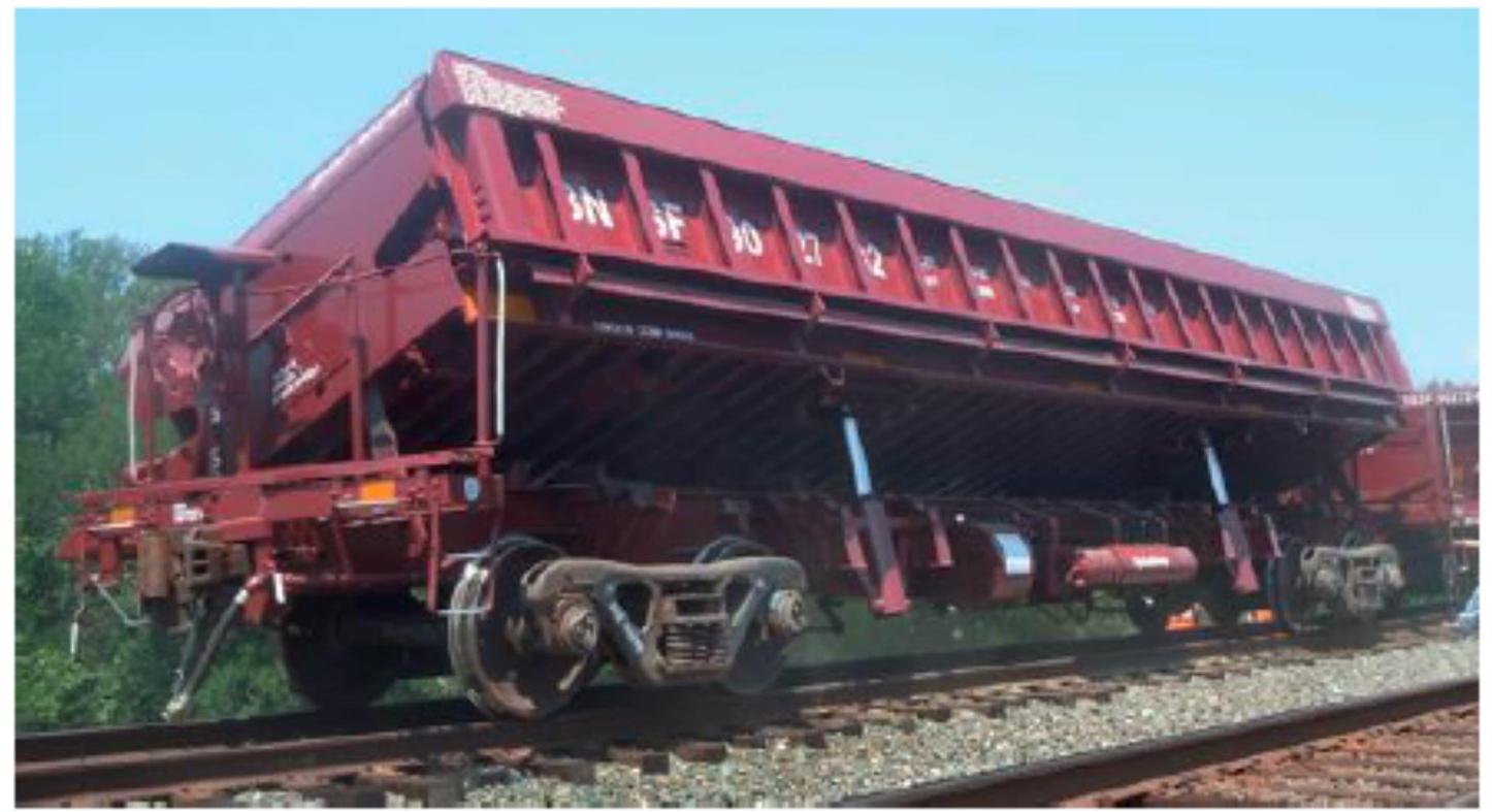
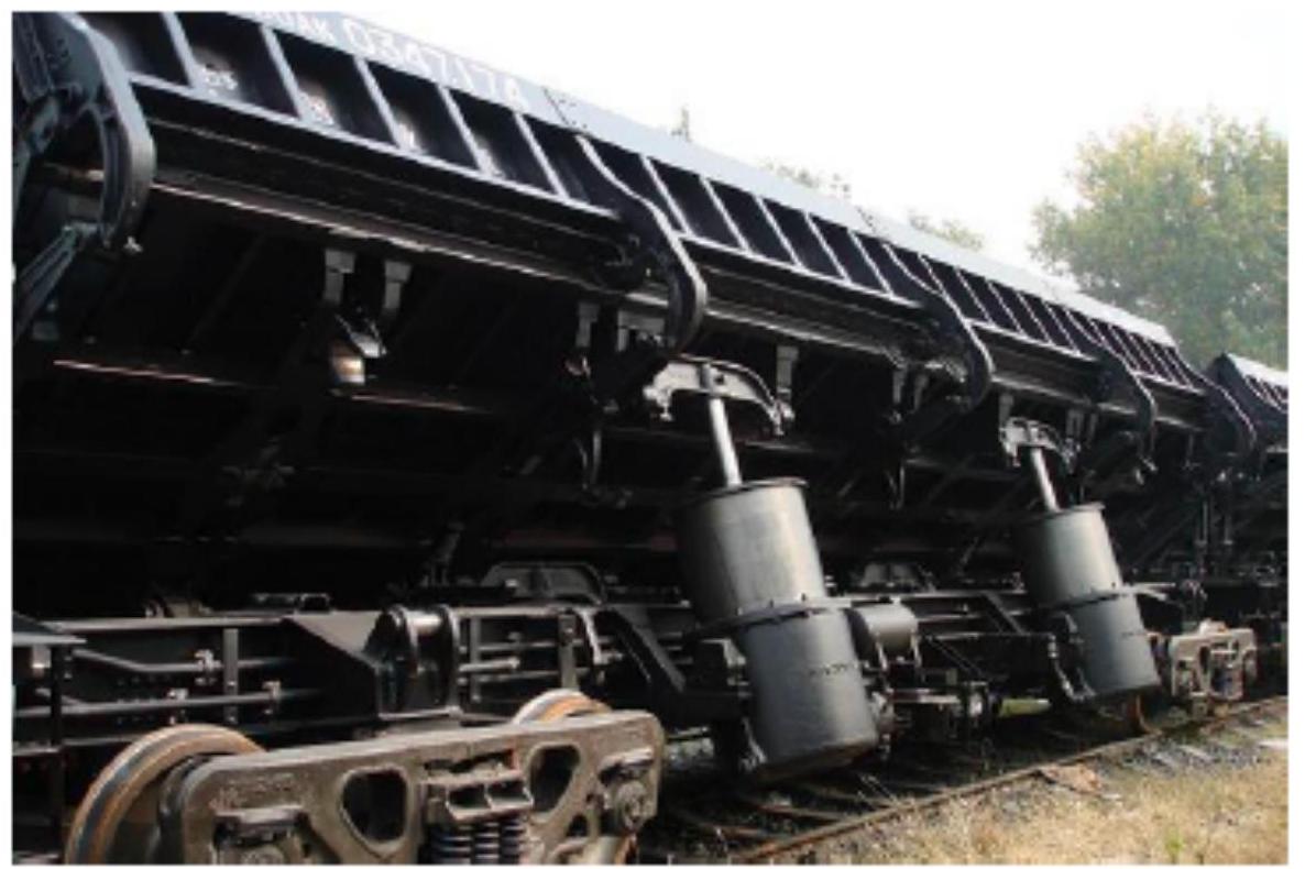
XII.2. Bulk Freight Wagon: Transport of Cereals and Similar Products
This type of wagon is specialized in the efficient transport of agricultural products and cereals in their granular form. The hopper design allows rapid loading and unloading via gravity or pneumatic systems. Products typically transported by this type of wagon include various types of cereals (wheat, rye, oats, barley, corn) requiring protection against moisture but allowing rapid loading/unloading operations.
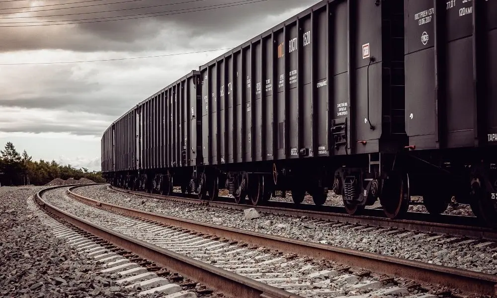
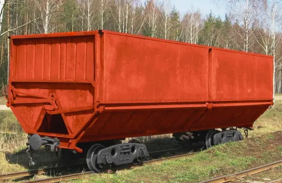
XII.2.1. Open Box or High-Sided Freight Wagon: Heavy Bulk Cargo
This type of wagon features an open structure at the top, allowing convenient loading and unloading from above using cranes or excavators. The absence of a cover allows loading of high-density bulk materials. Typical transport via this type of wagon includes materials such as mineral coal, metallurgical coke, railway ballast, construction gravel, and recycled metal scrap.
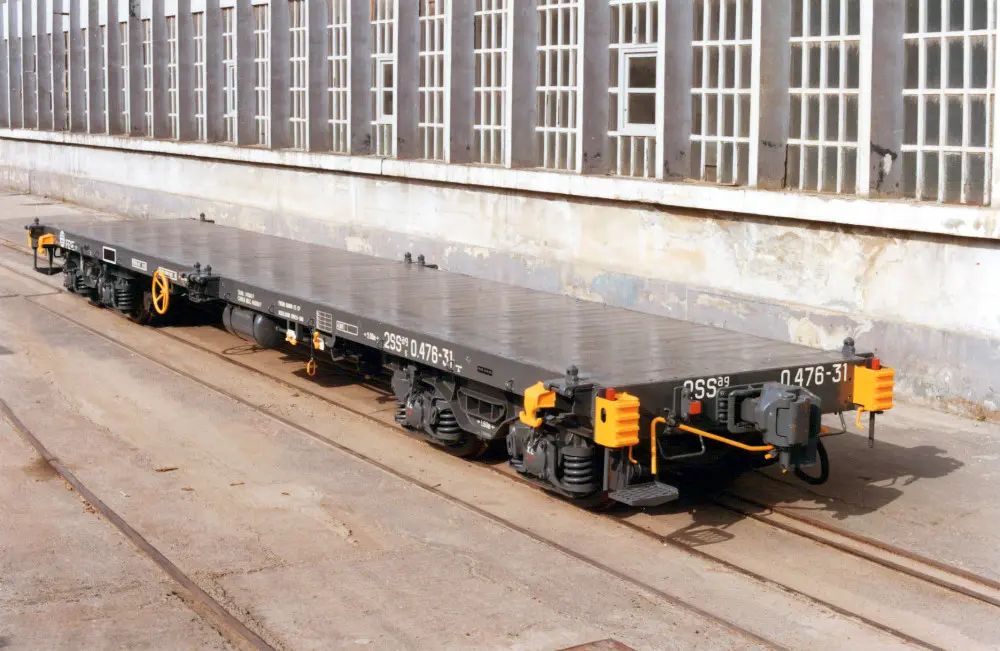
XII.3. Flat Freight Wagon: Transport of High Volume Cargo
Flat wagons are characterized by a fundamentally open structure, with a flat floor at low height, ideal for bulky loads distributed transversely. The absence of walls allows maximum flexibility in load shape and size. This type of wagon typically transports steel pipes, heavy machinery, steel bars and profiles, and wood products in the form of planks or beams.
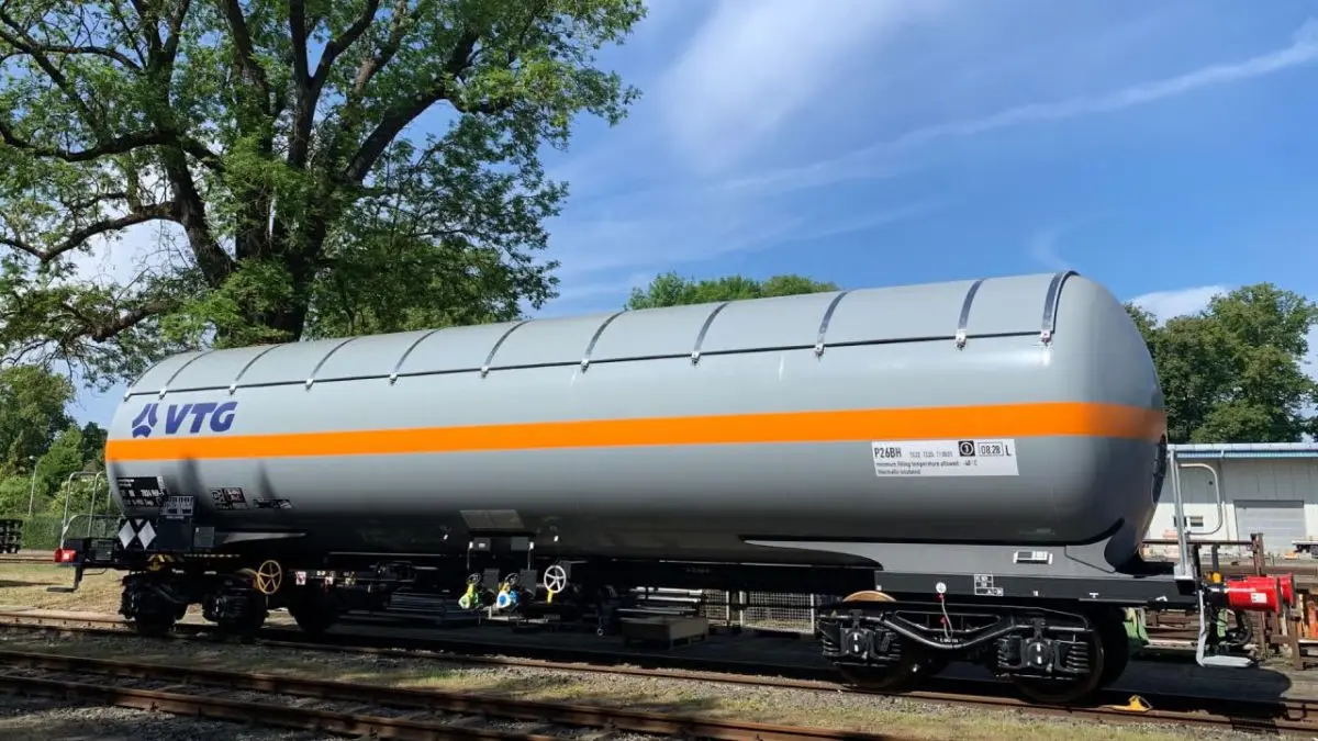
XII.4. Tank Freight Wagon: Transport of Liquids and Gases
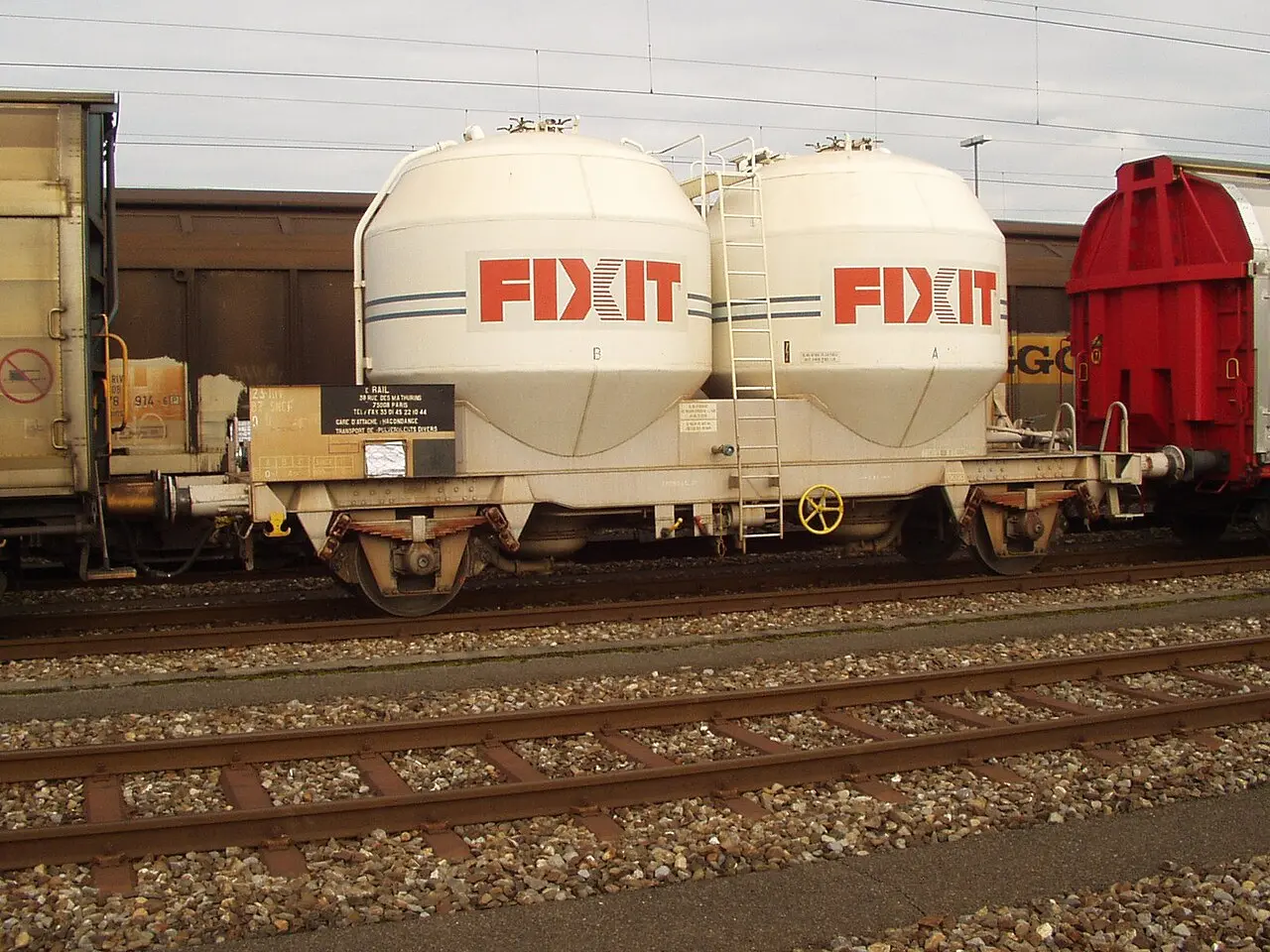
Tank wagons are specifically designed for the safe and efficient transport of products in liquid or gaseous states. The structure consists of steel tanks subjected to controlled pressure, provided with specialized loading and unloading systems. The diversity of products transported via railway tankers is very wide and includes industrial chemicals, refined mineral oils, liquefied gases under pressure (such as propane or butane), and other specialized products.
A special subcategory of tank wagons is dedicated to transporting construction materials and structural metal profiles requiring protection during transit:
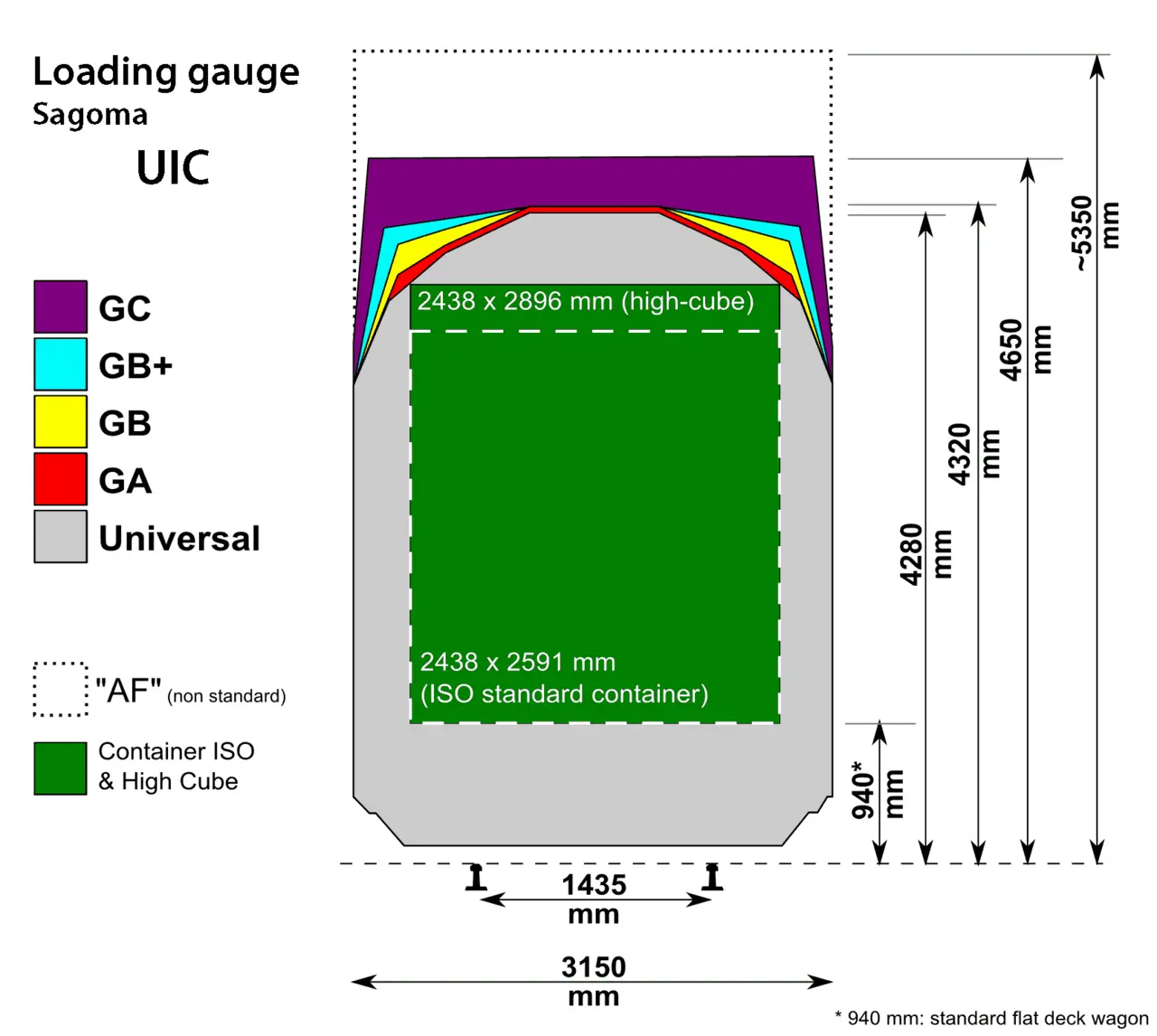
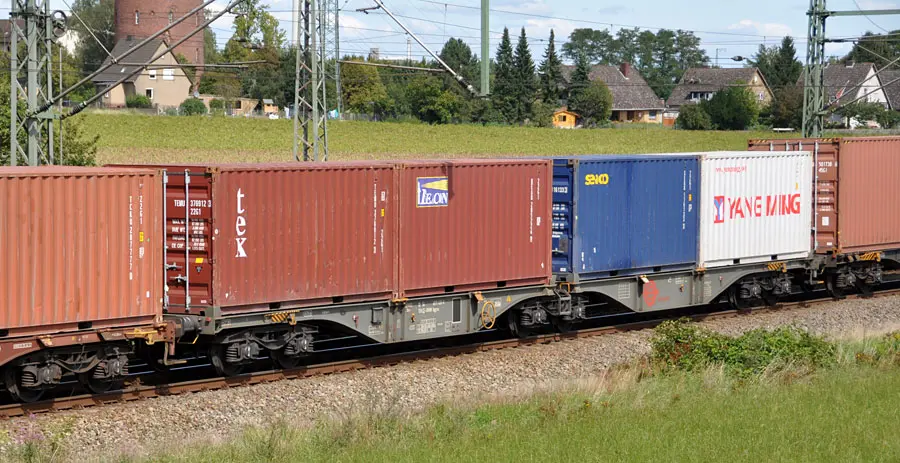
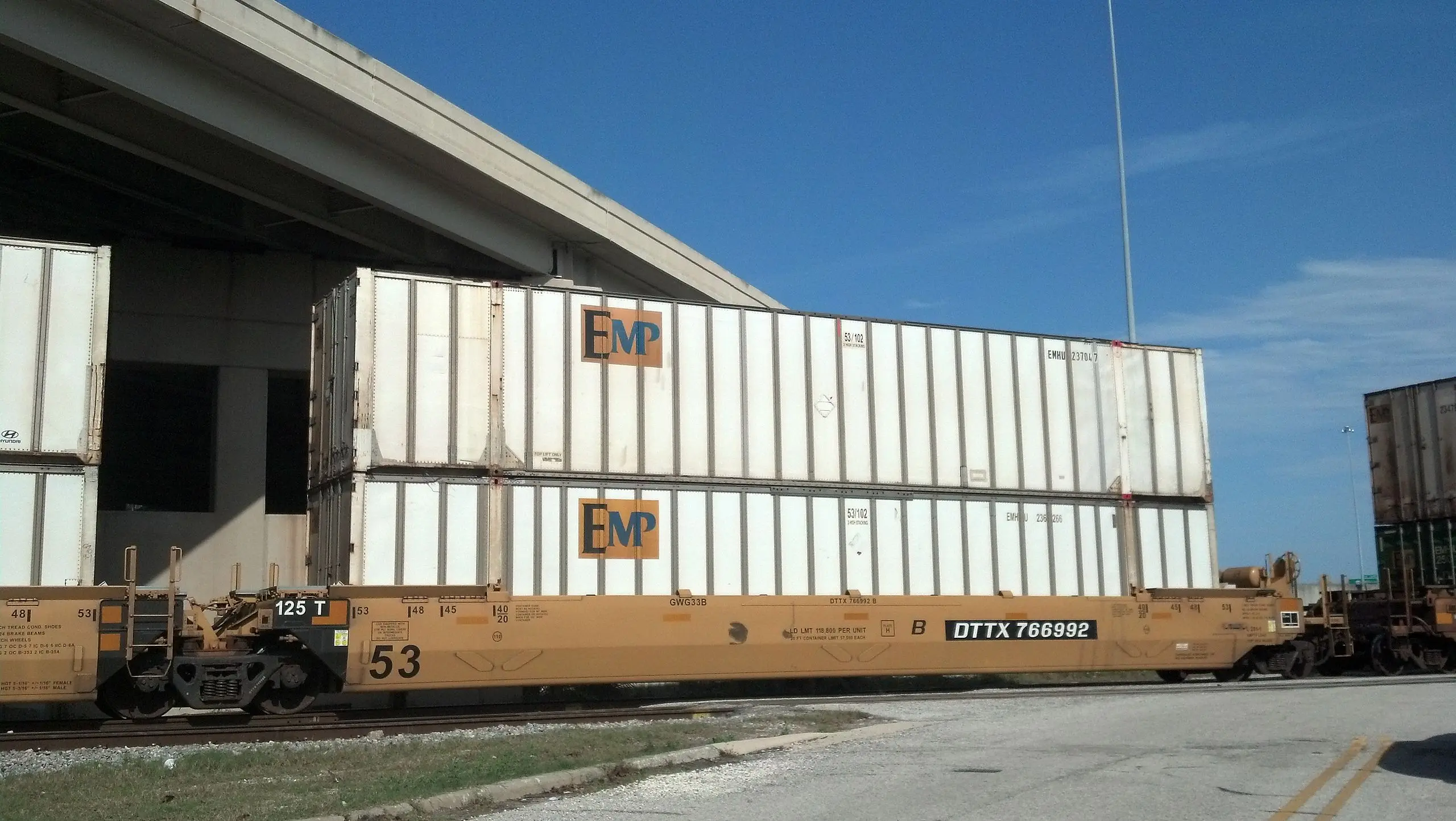
XII.5. Container Carrier Freight Wagon: Standardized Intermodal Transport
This type of wagon has revolutionized railway transport operation through its compatibility with standardized ISO containers. Container carrier wagons have standardized fastening systems allowing secure transport of containers of multiple sizes (20’, 40’, etc.). This configuration facilitates intermodal transfer between railway transport, road transport via trucks, and maritime transport via container ships.
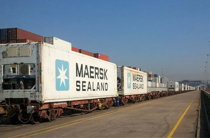
XII.6. Refrigerated Freight Wagon: Preservation of Perishable Products
This type of wagon incorporates active refrigeration systems allowing controlled temperatures to be maintained throughout the journey. These wagons are specially designed for the transport of perishable food products, including fresh food, meat products, frozen fish, fruits and vegetables, and other products requiring a controlled cold chain.
XII.6.1. Special or Customized Freight Wagons
Within the available wagon portfolio, there is an important category of wagons designed “to measure” according to specific customer operational requirements. These special wagons are customized to optimize the transport of very specific products that do not fit into standard categories.
Customized rail transport of specialized products allows wagon configuration to be adapted to the client’s very particular needs, optimizing operational efficiency and reducing damage risks during transit:
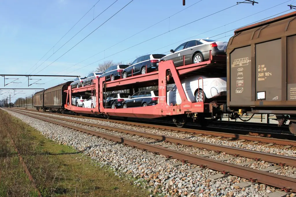
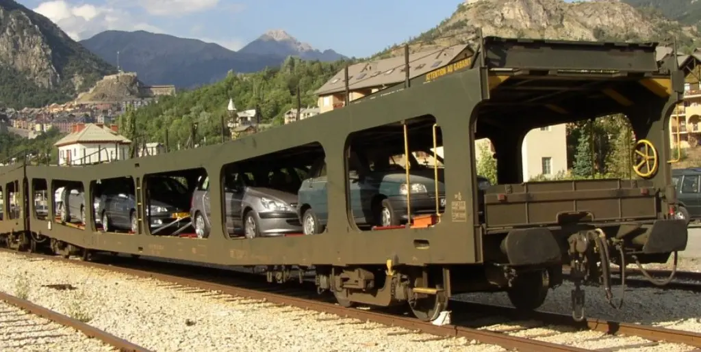
XII.7. Car Carrier Wagon
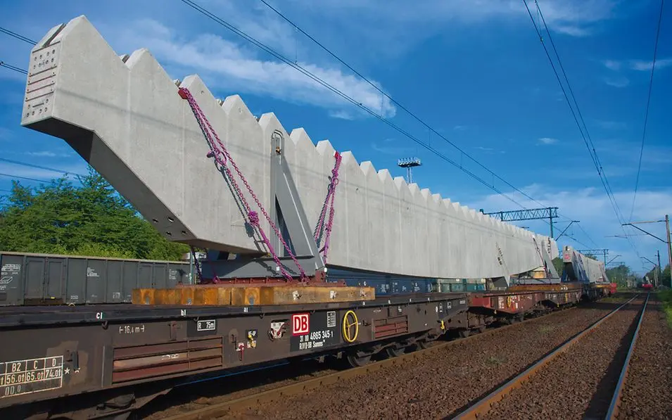
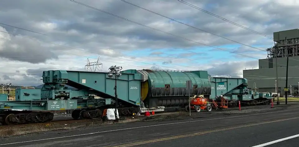
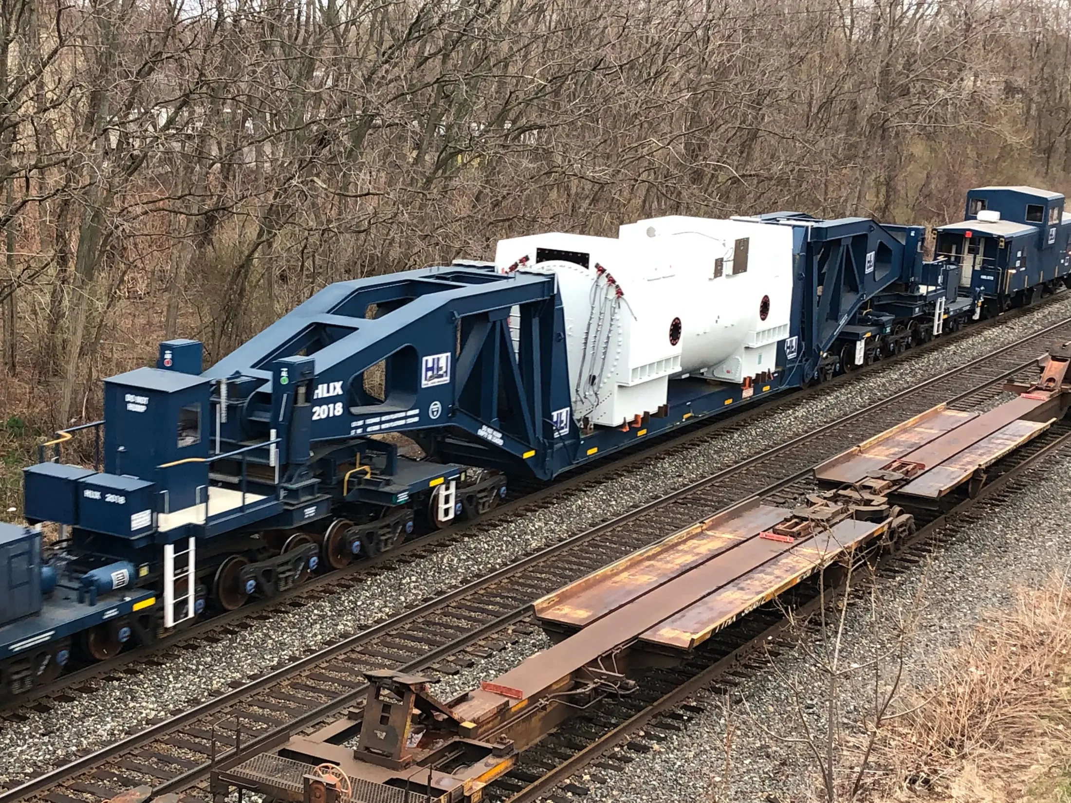
XII.8. ‘Schnabel’ Freight Wagon: Transport of Extraordinary Loads
The German name “schnabel” (meaning “beak” or “bill”) describes the characteristic shape of this specialized wagon. It is specifically designed for transporting heavy and oversized loads exceeding standard height or weight limits. The configuration allows load height to be reduced through special positioning within restrictive dimensional gauges.
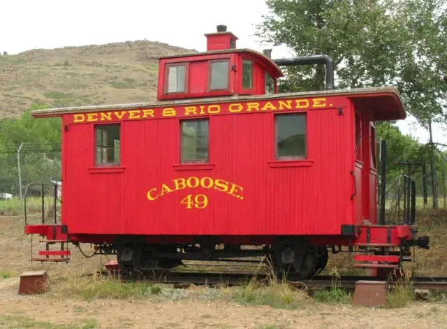
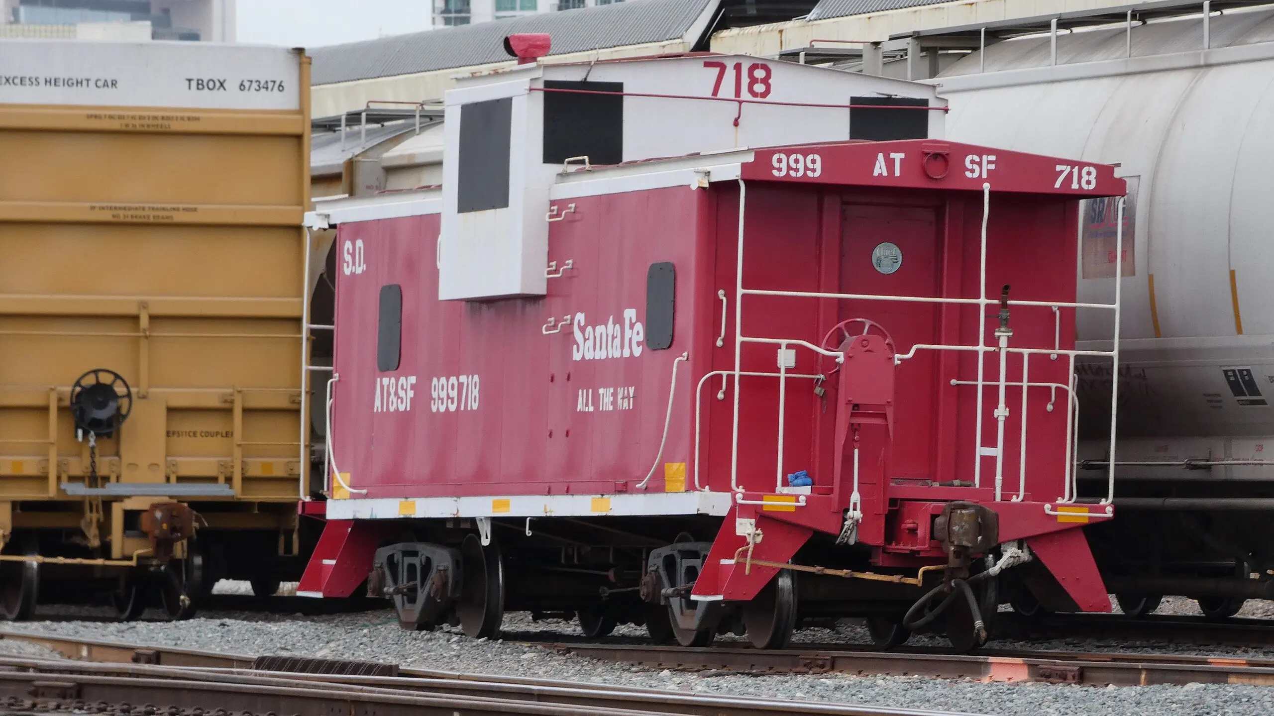
XII.9. ‘Caboose’ End Freight Wagon: North American Operational Tradition
The term “caboose” of North American origin describes a special type of wagon coupled at the end (rear) of traditional freight trains. Its function was to provide accommodation for the train crew and serve as an observation point from which workers could assist in switching operations, monitor the train during travel, and ensure train safety. With the modernization of railway systems and the implementation of remote controls, this type of wagon has ceased to be common, although it represents an important historical element in railway transport evolution.
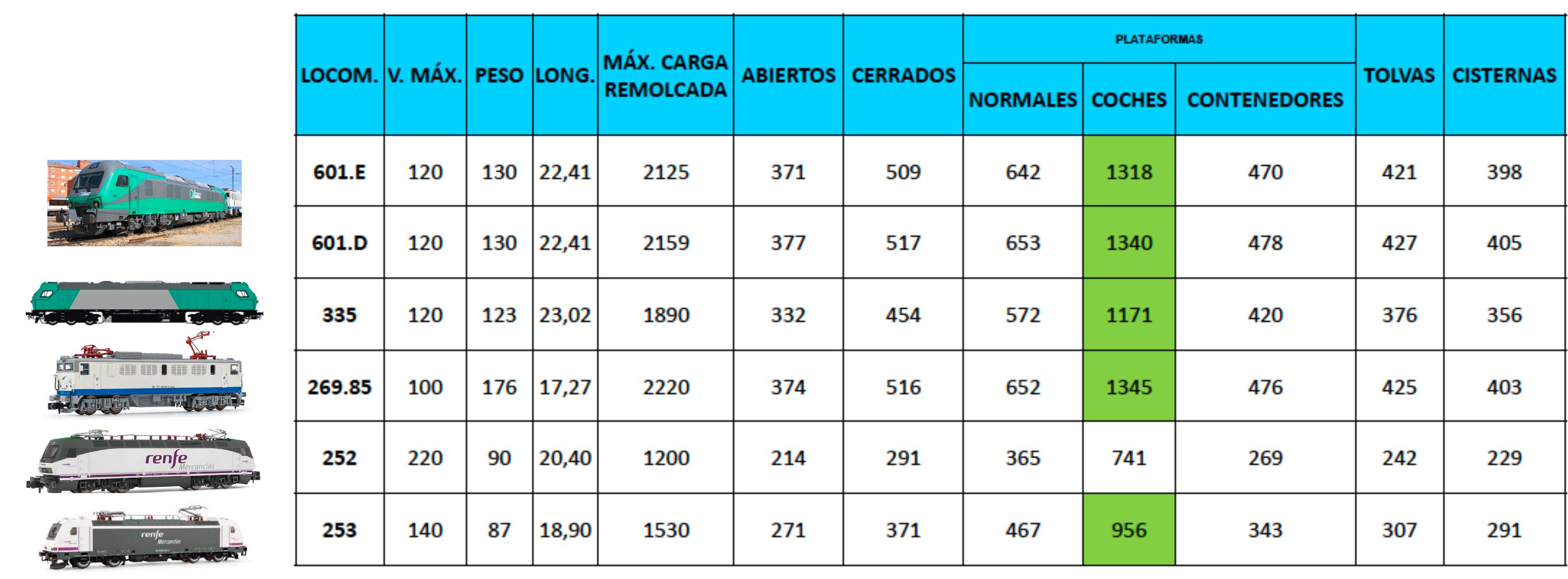
XII.10. Freight Train Compositions: Technical Specifications of Standard Compositions
The following tables present standardized technical specifications for freight train compositions operating on standard gradients. These data allow understanding the operational capabilities of different train types:
| OPEN | CLOSED | FLAT | HOPPERS | TANKERS | |||
|---|---|---|---|---|---|---|---|
| NORMAL | CARS | CONTAINERS | |||||
| Max Length (m) | 14 | 22 | 28 | 26 | 27 | 18 | 17 |
| Max Weight (t) | 80 | 90 | 90 | 40 | 120 | 90 | 90 |
| Max Speed (km/h) | 100 | 120 | 120 | 160 | 120 | 120 | 120 |
Freight Compositions with 12‰ Gradient
For lines with gradients up to 12 per thousand (moderate gradients), compositions are configured with the following parameters:
Freight Compositions with 18‰ Gradient
For mountain lines with gradients up to 18 per thousand (demanding gradients), lighter compositions are required to allow acceptable operating speeds:
| Locomotive | Max V. (km/h) | Weight (t) | Length (m) | Max Towed Load (t) | Open Wagons | Closed Wagons | Normal Flat Wagons | Cars | Containers | Hoppers | Tankers |
|---|---|---|---|---|---|---|---|---|---|---|---|
| 601.E | 120 | 130 | 22.41 | 1517 | 264 | 361 | 453 | 923 | 334 | 299 | 283 |
| 601.D | 120 | 130 | 22.41 | 1522 | 265 | 362 | 455 | 926 | 335 | 300 | 284 |
| 335 | 120 | 123 | 23.02 | 1340 | 235 | 320 | 401 | 814 | 296 | 266 | 252 |
| 269.85 | 100 | 176 | 17.27 | 1580 | 262 | 360 | 453 | 929 | 332 | 297 | 282 |
| 252 | 220 | 90 | 20.40 | 880 | 158 | 213 | 265 | 533 | 197 | 178 | 169 |
| 253 | 140 | 87 | 18.90 | 1080 | 192 | 261 | 327 | 664 | 242 | 217 | 206 |
These data demonstrate how available towing capacity is distributed among different wagon types, reflecting the hierarchy of weights and load volumes typical in railway operation.
Chapter XIII. Coupling Systems: Mechanical, Pneumatic and Electrical Coupling
Couplers or draft gears constitute fundamental devices that perform multiple critical functions simultaneously: they perform the mechanical coupling of railway vehicles, facilitate the transmission of longitudinal forces (traction and braking), absorb impacts and dynamic oscillations derived from operation, and in modern systems, transmit pneumatic and electrical signals between coupled vehicles.
FUNDAMENTAL CLASSIFICATION OF COUPLERS
Two main categories of couplers are distinguished according to their operational function and the nature of the coupling:
-
Automatic couplers: These specialized devices provide automatic coupling between units without manual intervention. They are located at the headstocks (ends) of the vehicles and allow rapid coupling of compositions. Once coupled, these couplers lock automatically through mechanical locking systems.
-
Semi-permanent couplers: These couplers connect vehicles forming train units more stably, typically requiring the active intervention of an operator to carry out coupling and decoupling. This type of coupling is more frequent in maintenance workshop contexts where compositions are modified.
Jaw Coupler
- Advanced Automatic or Integral Couplers:
More sophisticated coupling systems exist that integrate multiple functions into a single specialized device. These systems combine in a single device the traction function, absorption of impacts and dynamic oscillations, transmission of pneumatic signals for brake systems, and transmission of electrical signals. These integral couplers are especially used in metro and rapid urban transport systems.
A representative example is the Scharffenberg coupler type, which is very frequently used between latest generation self-propelled trains. This design allows coupling operations with extreme ease and security.
Capabilities and Functionalities of Modern Automatic Couplers
-
Multiple coupling of two or more trains is effected via automatic couplers, which are located at the headstocks (longitudinal ends) of each composition.
- Once two trains are coupled via latest generation automatic coupling systems, the system allows centralized multiple control from a single driving cab, providing the single driver with integrated control of:
- Traction systems of both units
- Brake systems of the entire multiple composition
- Transmission of rearview camera images from all ends of the composition
- Monitoring of doors and locking systems
- All parameters necessary to guarantee safe driving
-
Modern automatic couplers provide rescue capability between trains. Any failed composition can be coupled to any other available composition on the railway network for towing.
- The coupler incorporates a sophisticated self-recovering impact absorption system, designed to absorb longitudinal impacts occurring between coupled units. The capacity of this system is very high, allowing controlled contact between a completely stopped unit and another in motion (both at maximum load) at speeds exceeding ordinary coupling speed, which is typically 3 km/h.
Chapter XIV. Passenger Transport: Passenger Coaches and Composition Architecture
The design of passenger vehicles requires technical and operational considerations very different from freight transport. The fundamental priority is to provide comfort, safety, and accessibility to passengers, while maintaining adequate operational performance and economic efficiency.
BODY CONFIGURATION
Passenger coaches can be classified according to fundamental characteristics of their structure:
Single-deck or Double-deck Coaches
The selection of the number of levels is a fundamental design decision that significantly affects passenger capacity, comfort, and operational characteristics:
- Conventional single-deck coaches are the most traditional configuration, maximizing passenger comfort and simplifying access
- Double-deck coaches increase passenger transport capacity (typically by 35-40%) by using available space more efficiently, although with some limitations in comfort and restrictions on lines with limited gauges
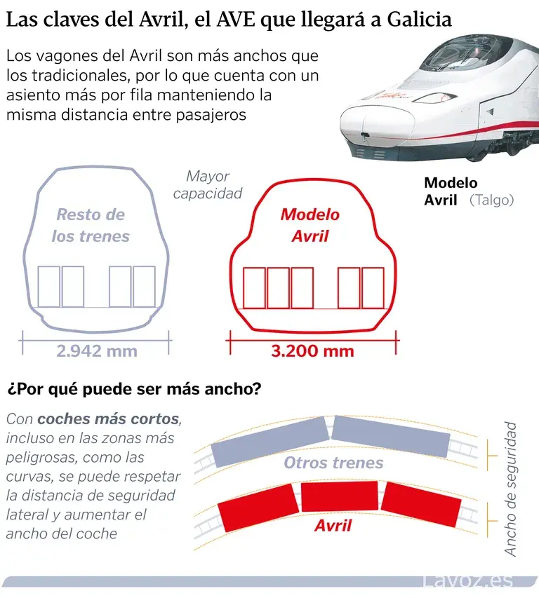
Standard Width vs Extended Width Bodies
The lateral dimension of the carbody represents a compromise between capacity, access to standardized platforms, and available gauges:
- Standard width coaches respond to traditional width standards optimized for compatibility with existing infrastructure
- Wide body coaches (within permitted gauges) provide greater interior space for passengers and services, significantly improving comfort
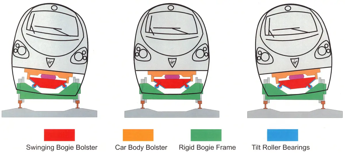
Suspension Systems: Rigid, Tilting and Pendular Coaches
The ability to tilt in curves constitutes an important operational parameter affecting both comfort and permissible speed:
- Non-tilting coaches: Use conventional suspension systems, limiting speed in curves to guarantee adequate comfort
- Tilting coaches (Basculantes): Incorporate active or semi-active systems allowing controlled tilting of the carbody interior in curves, significantly improving comfort and allowing higher speeds without discomfort
- Pendular coaches: Use advanced mechanisms allowing maximum tilting leveraging track superelevation (cant), allowing operation at higher speeds on curved lines
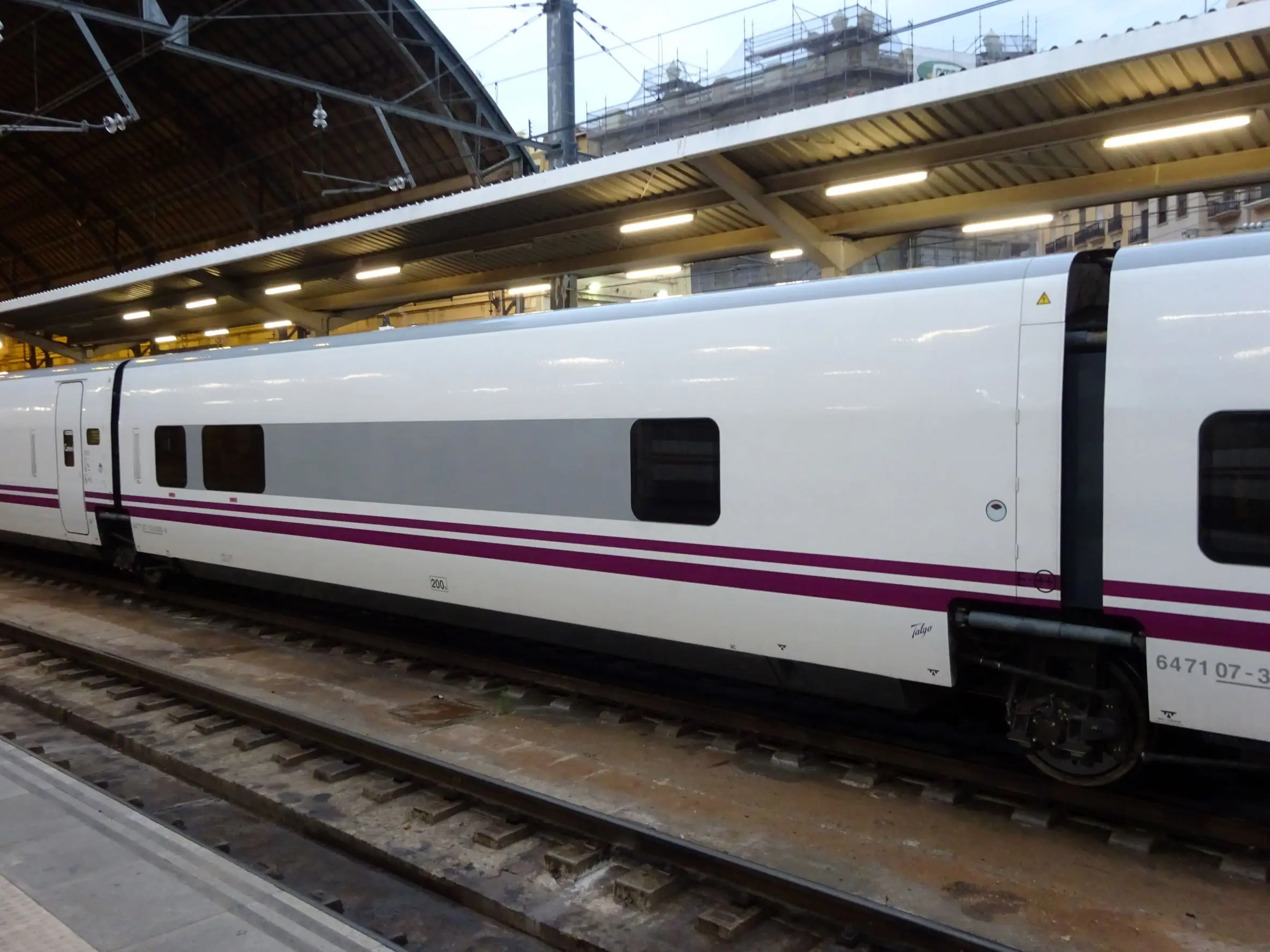
ACTIVE PENDOLINO SYSTEM
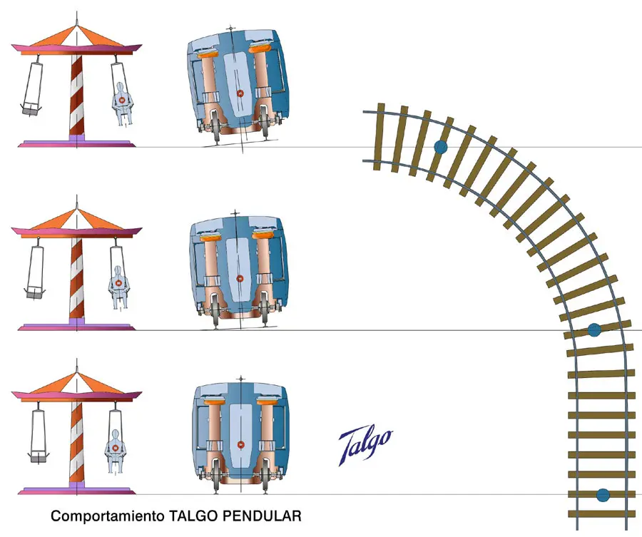
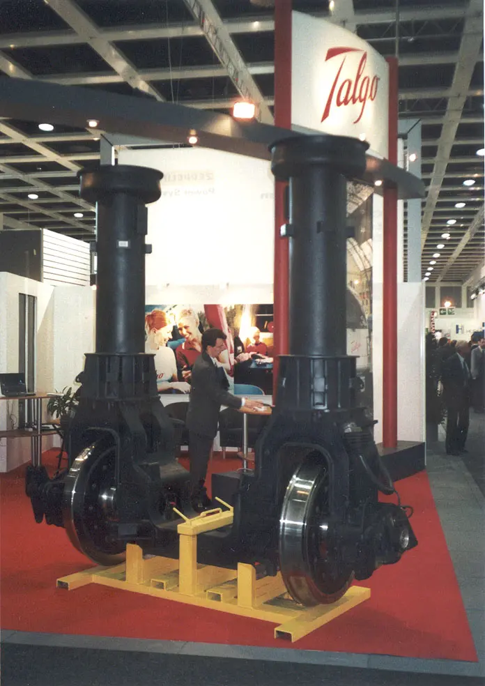 PASSIVE TALGO SYSTEM
XIV.1. Passenger Coaches: Design Characteristics and Operational Configuration
FUNDAMENTAL DESIGN PARAMETERS
The design of a passenger coach is structured around several critical parameters determining its functionality:
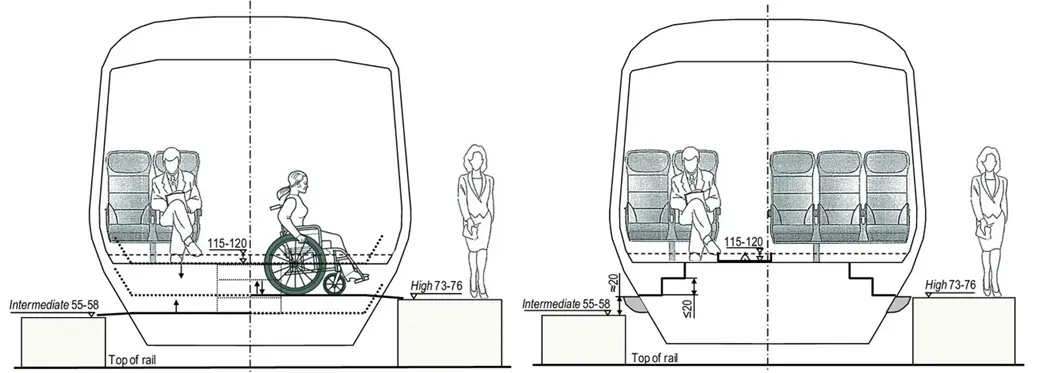
- Floor height above rail level: Affects passenger accessibility, particularly persons with reduced mobility. Modern standards favor low floors (around 550 mm) for step-free access at appropriately designed stations
- Number and width of doors: Determines passenger boarding and alighting capacity, directly affecting station dwell times
- Seating distribution and configuration: Defines seated versus standing passenger capacity, general comfort, and versatility for different services
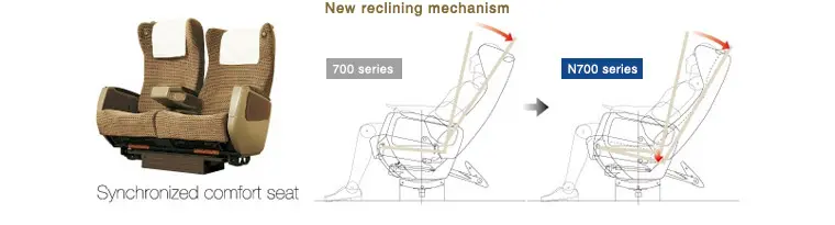
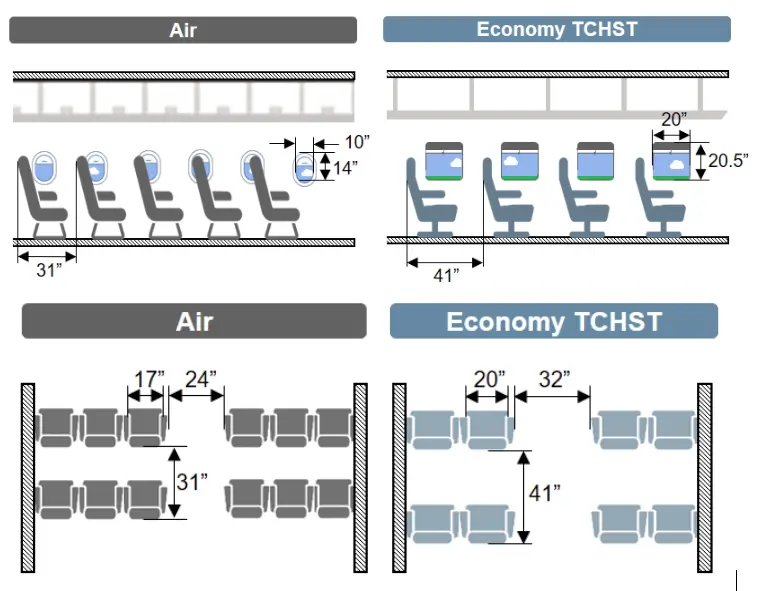
SPECIALIZED COACH TYPOLOGIES
Railway passenger transport has developed multiple specialized coach typologies, each optimized for specific operational functions:
- Standard passenger coaches: Constitute the most common typology, designed for high volume passenger transport
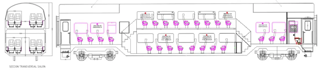
- Lounge coaches (Salón): Equipped with superior quality seating layout and integrated food/beverage services
- Compartment coaches: Divided into private compartments for small groups or travelers preferring privacy
- Sleeping cars (Coches cama): Equipped with overnight accommodation systems, critical for international long-distance trains
- Restaurant or bar coaches: Dedicated to food and beverage service, allowing passengers to eat without leaving the train
- Panoramic coaches: Equipped with enlarged windows or exterior views for landscape observation, typical on tourist lines
- Multiple specialized configurations according to operational needs
XIV.2. Operational Configurations of Passenger Rolling Stock by Service Type
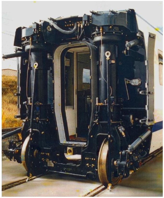
DISTINCTION BETWEEN FIXED AND VARIABLE GAUGES
Spanish and European railway systems present an important operational characteristic: the existence of multiple track gauges (Iberian gauge 1668 mm, Standard European gauge 1435 mm, Metric gauge 1000 mm). This has generated two design strategies:
- Fixed gauge systems: Designed for a specific gauge, optimized for performance but with interoperability limitations
- Variable gauge systems: Equipped with adaptable wheel systems allowing circulation on tracks of different gauges, providing maximum flexibility but with slight reductions in performance
FIXED GAUGE
VARIABLE GAUGE
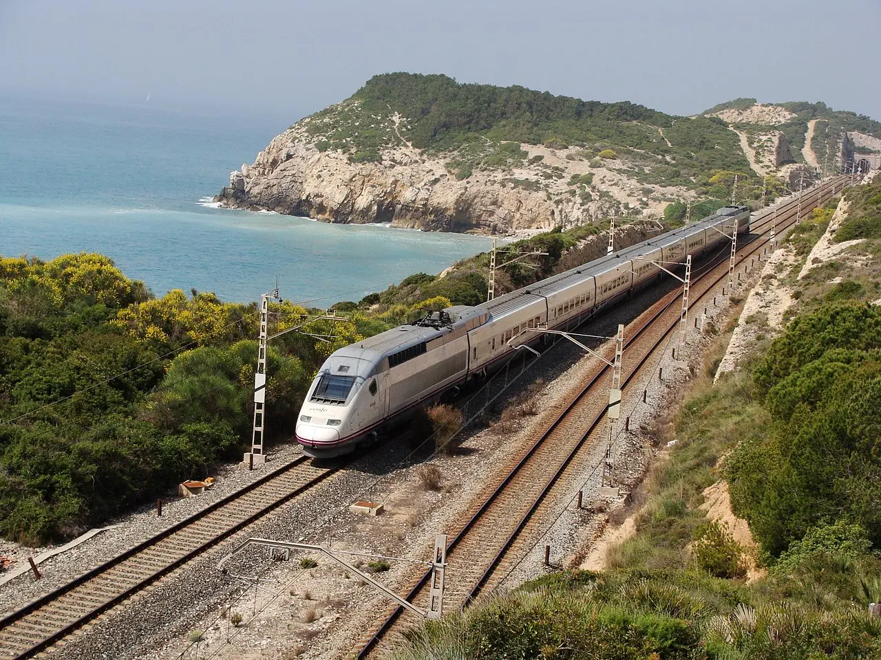
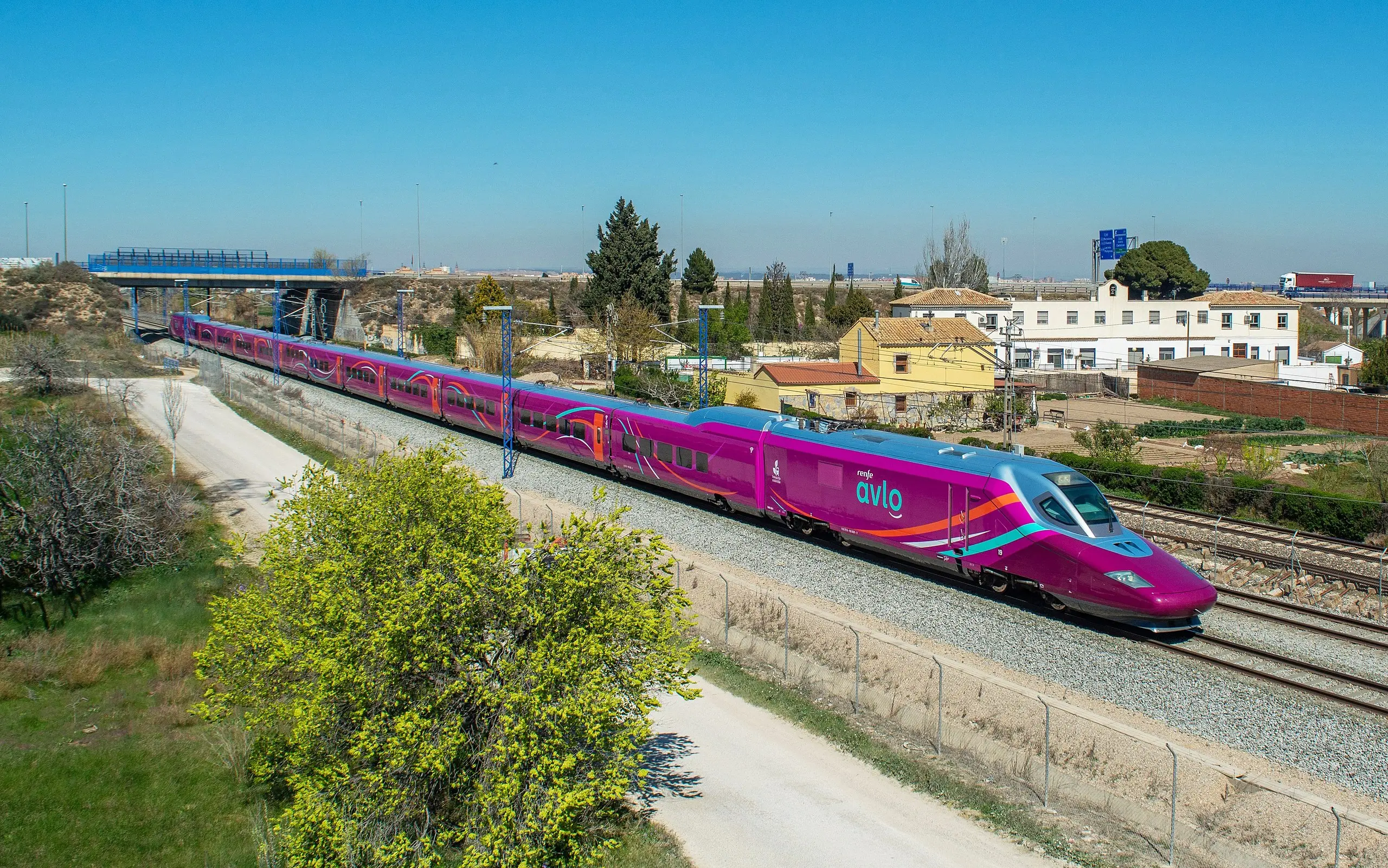
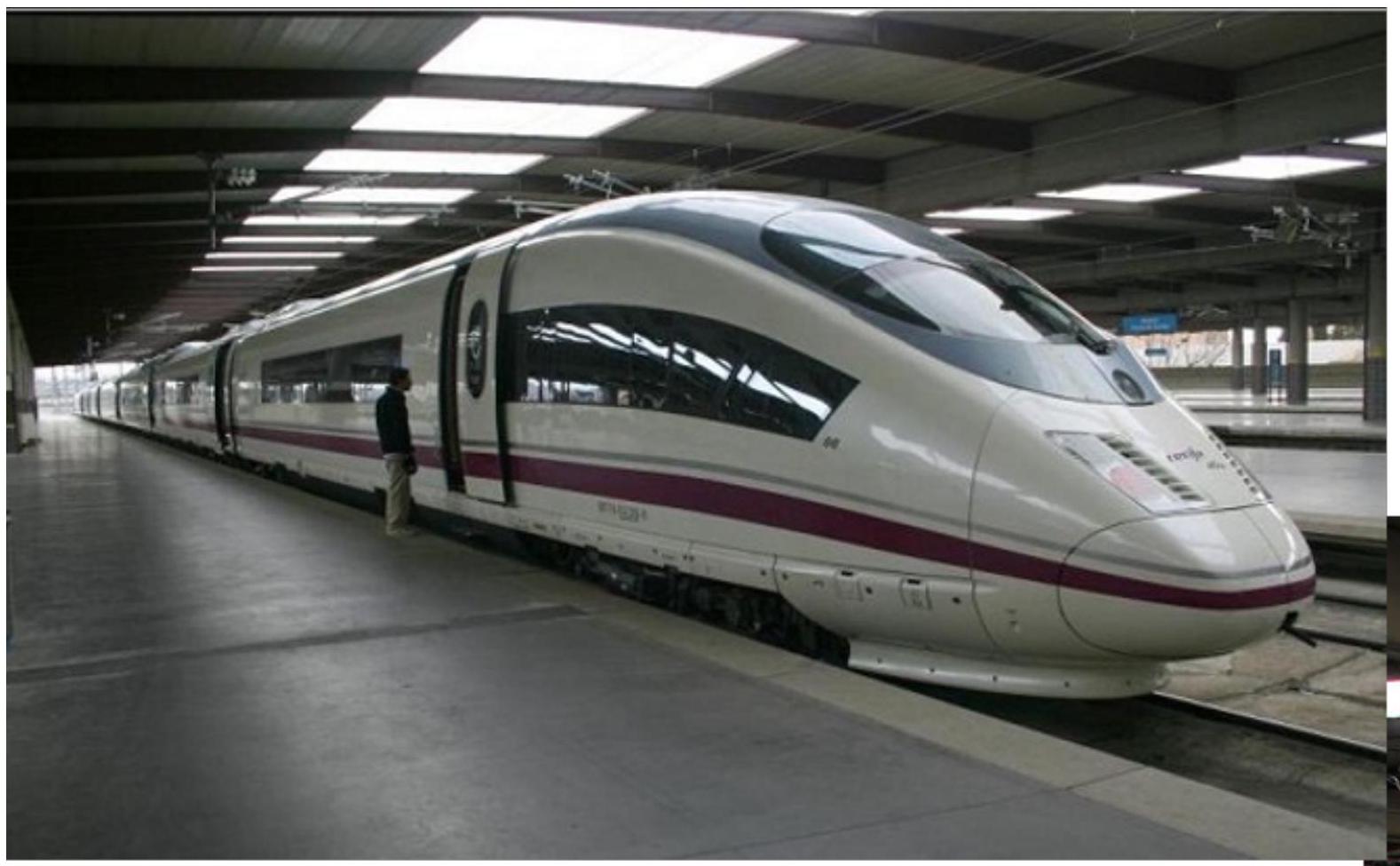
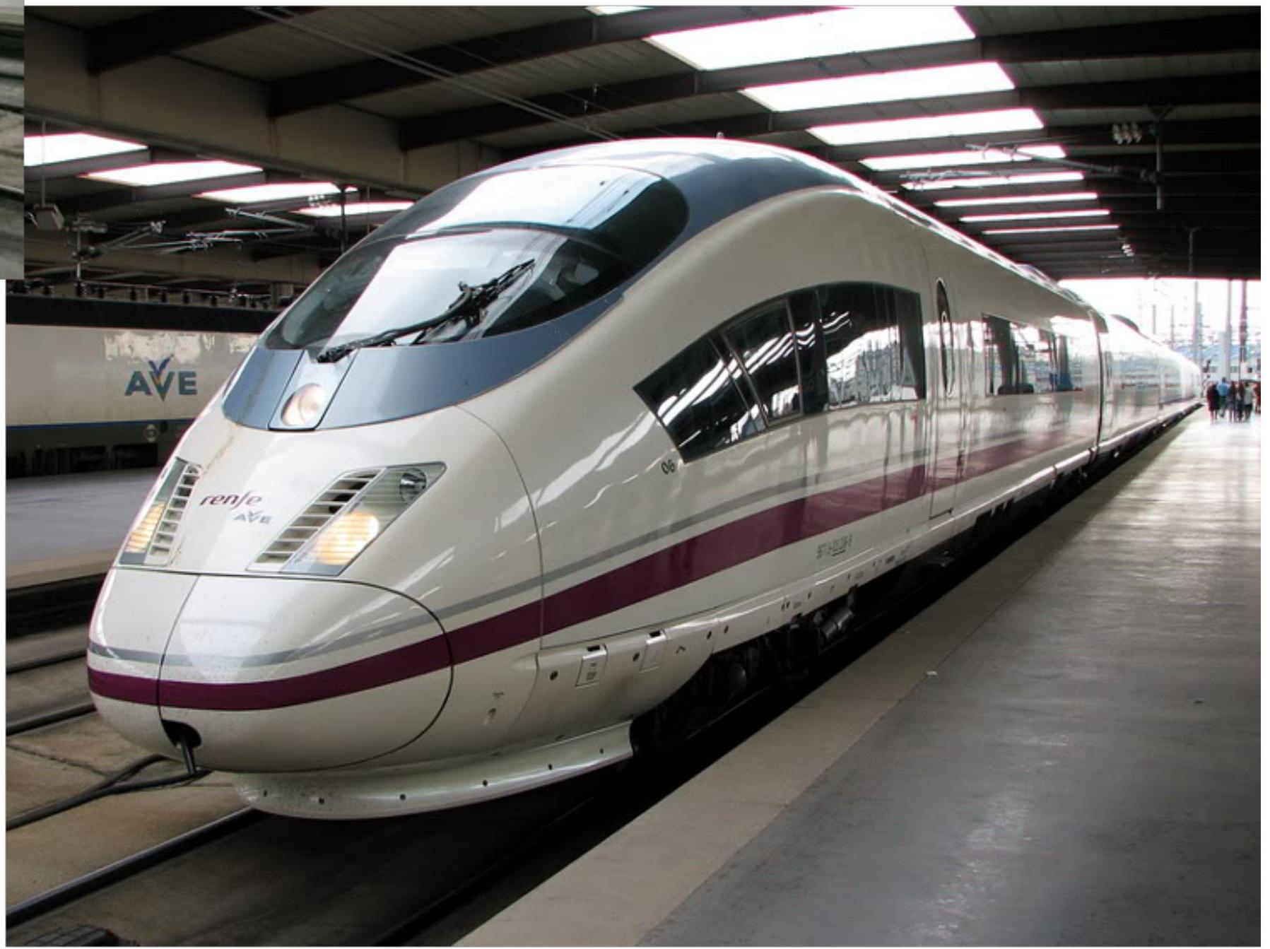
XIV.2.1. High Speed Trains (AVE): Maximum Performance Transport
High-speed trains represent the maximum frontier of performance in railway transport. Specifically designed for operation at speeds exceeding 300 km/h on very precise infrastructure lines:
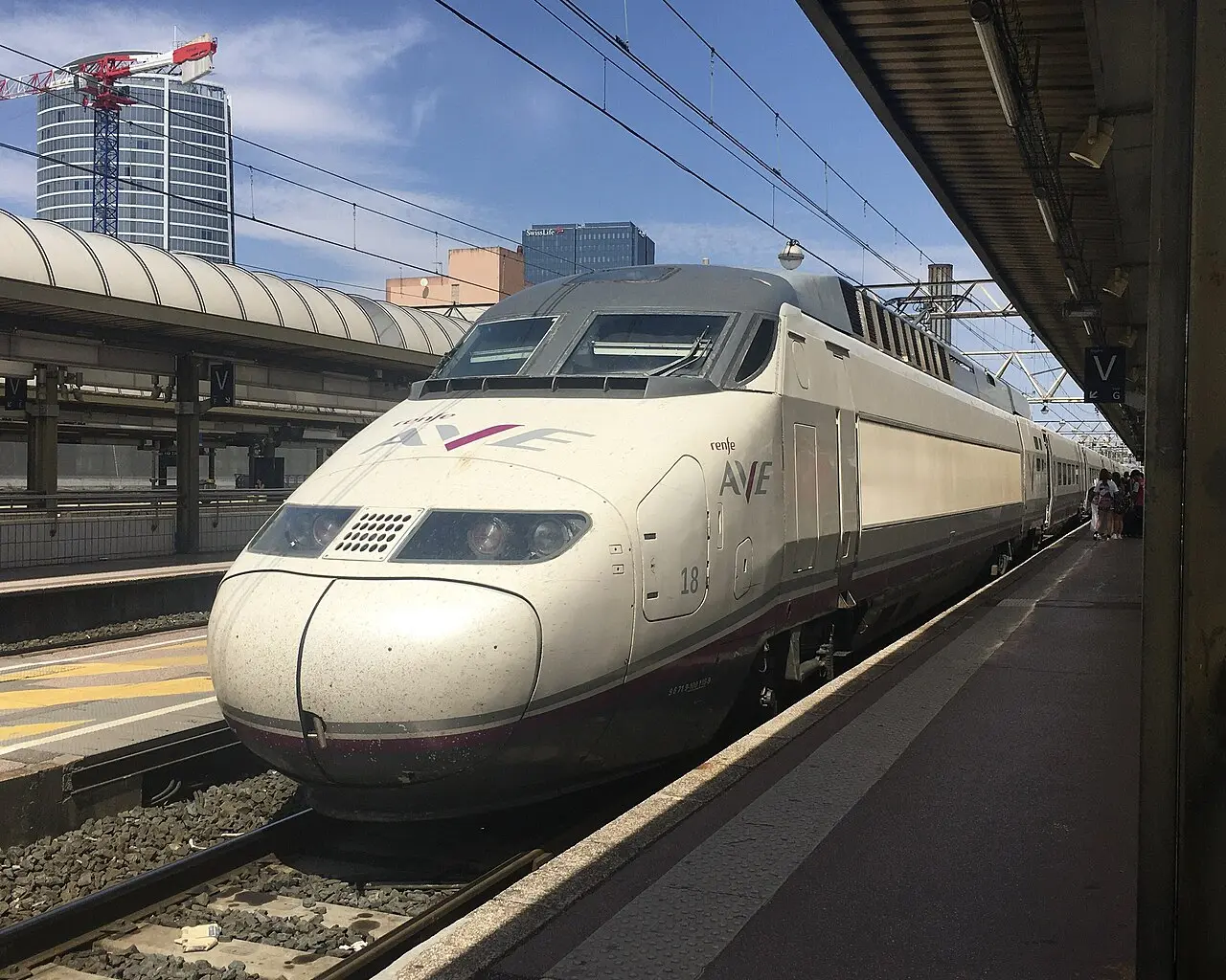
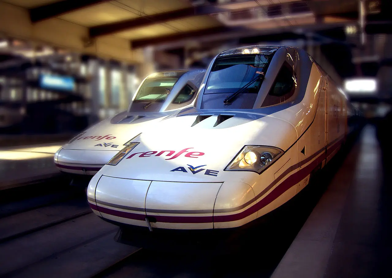 High-speed systems require extraordinary geometric precision in railway infrastructure and very sophisticated traction and control systems. Dynamic performance and passenger comfort reach unprecedented levels.
XIV.2.2. Alvia Trains: Long Distance Multi-standard Compatibility
Alvia trains represent an important operational solution for long-distance services requiring circulation on multiple infrastructure sections with different characteristics (speeds, track gauges, electrification):
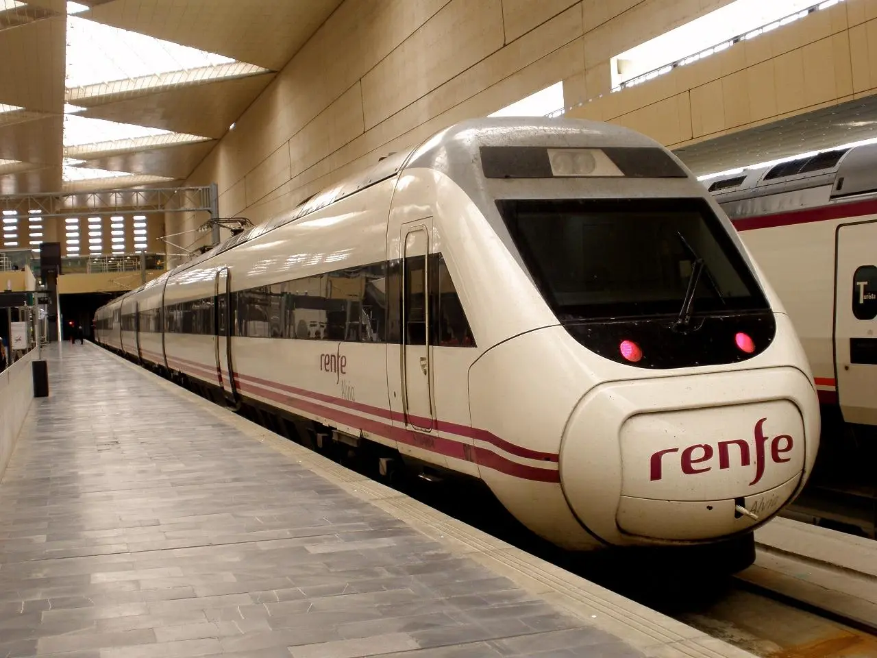
Series 120 CAF: Represent a very successful multi-standard diesel traction Spanish design
Series 130 Talgo/Bombardier: Another important solution for long-distance services with multiple system compatibility
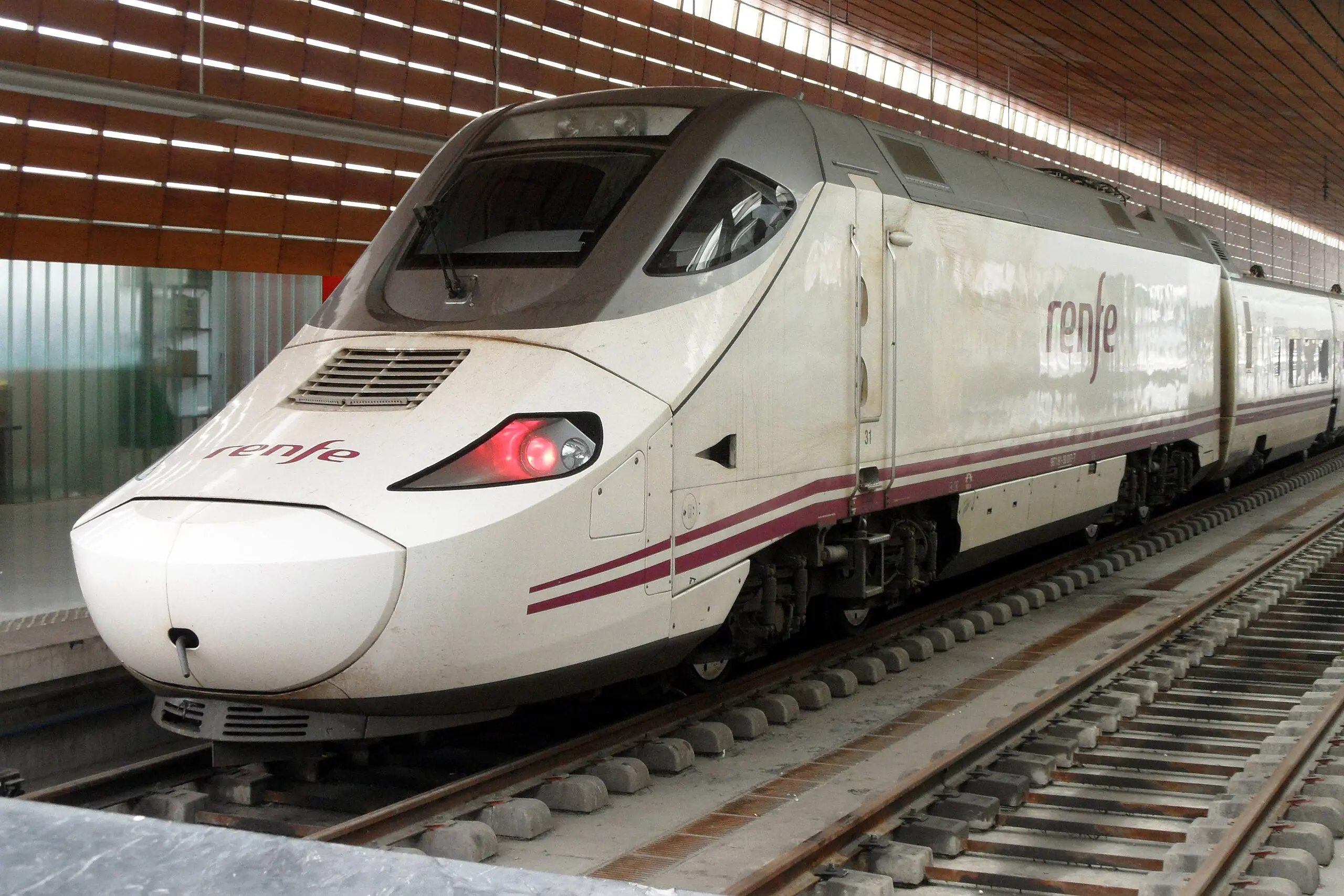
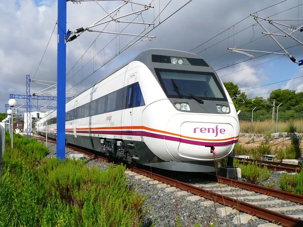
XIV.2.3. Avant Trains: Optimized Medium Distance Services
Avant trains are specifically designed for medium-distance services, providing a balance between performance, comfort, and operational efficiency:
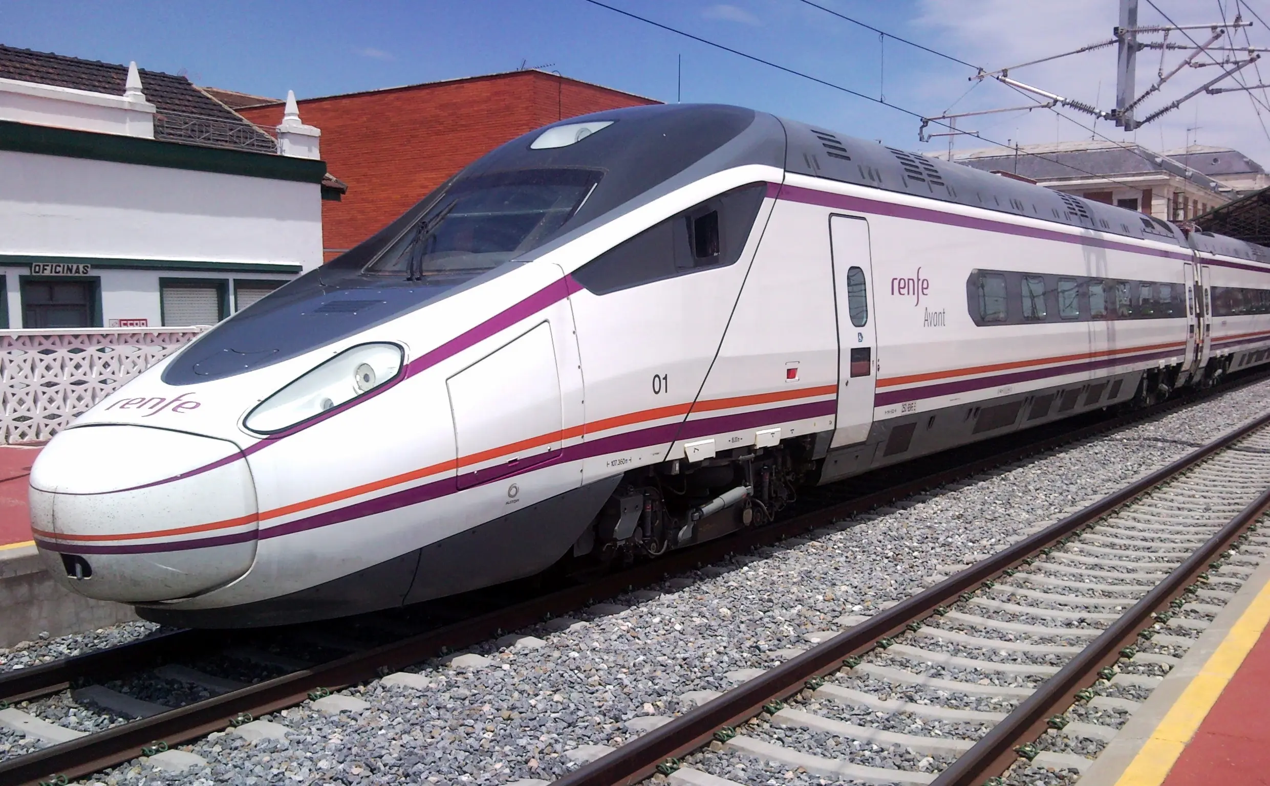
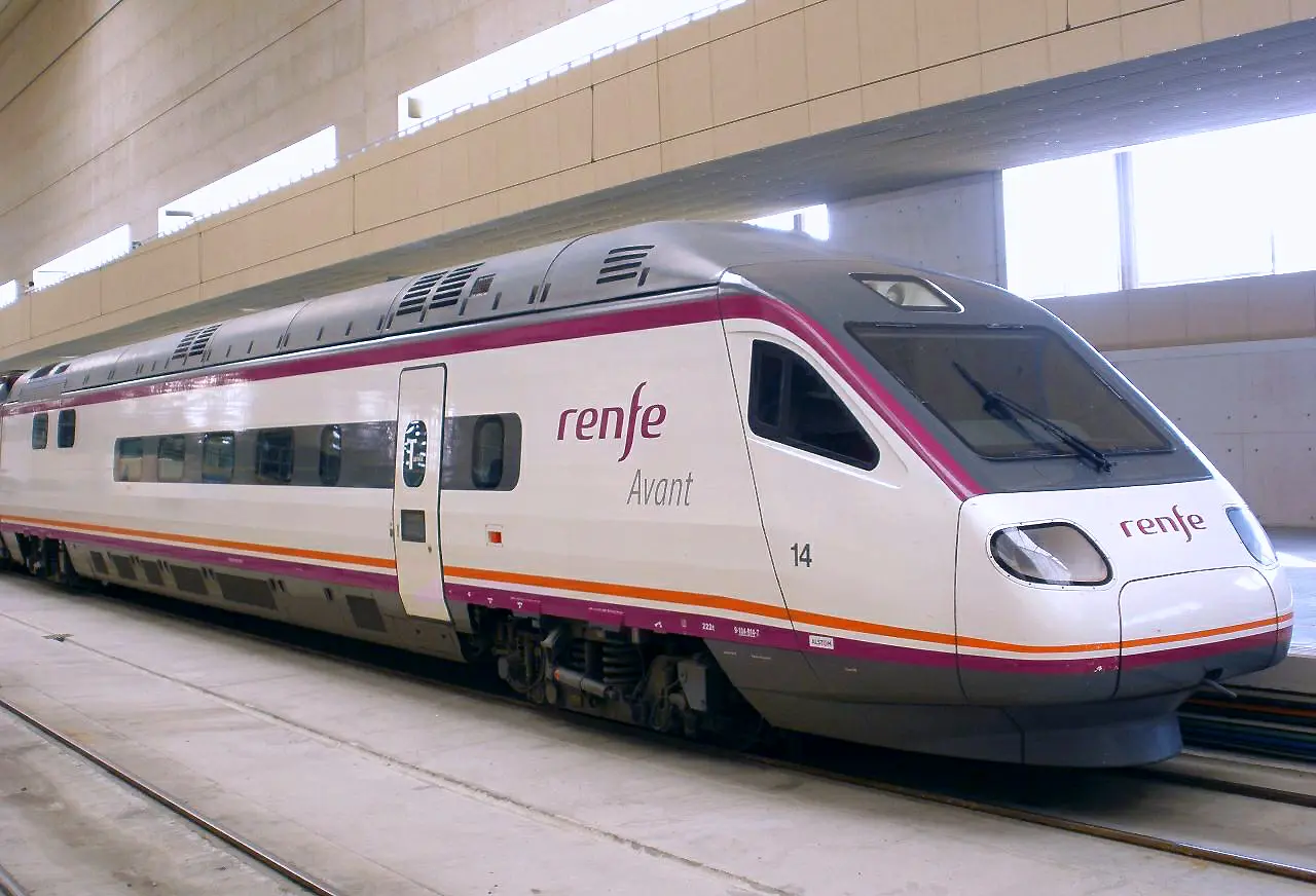
Series 104 Alstom/CAF: Modern medium-distance design combining diesel or electric traction with versatile configuration capacity
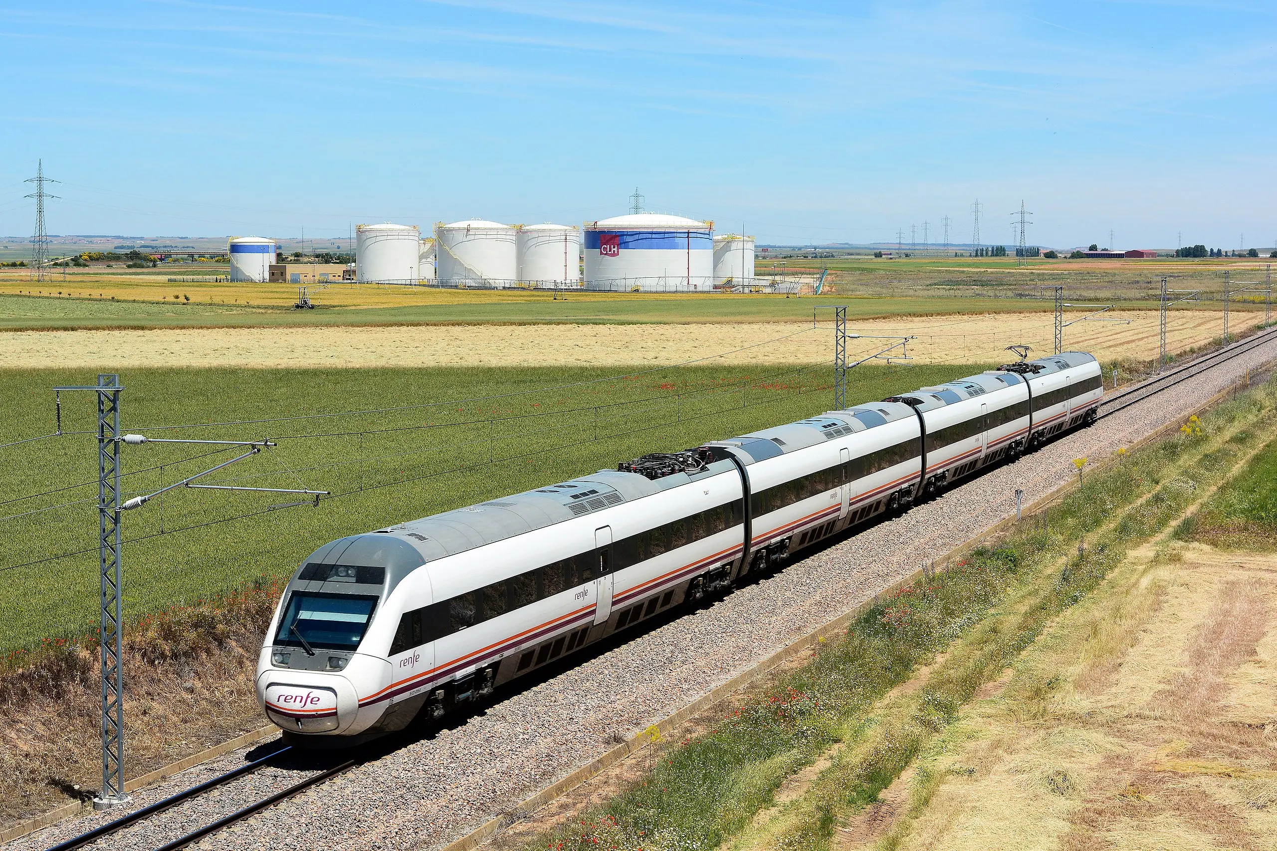
XIV.2.4. Medium Distance Services: Capacities and Configurations
Medium-distance services represent a critical operational segment in European networks, providing regional connectivity between main cities. Compositions are designed for operation with moderate frequencies but over more extensive distances than commuter services:
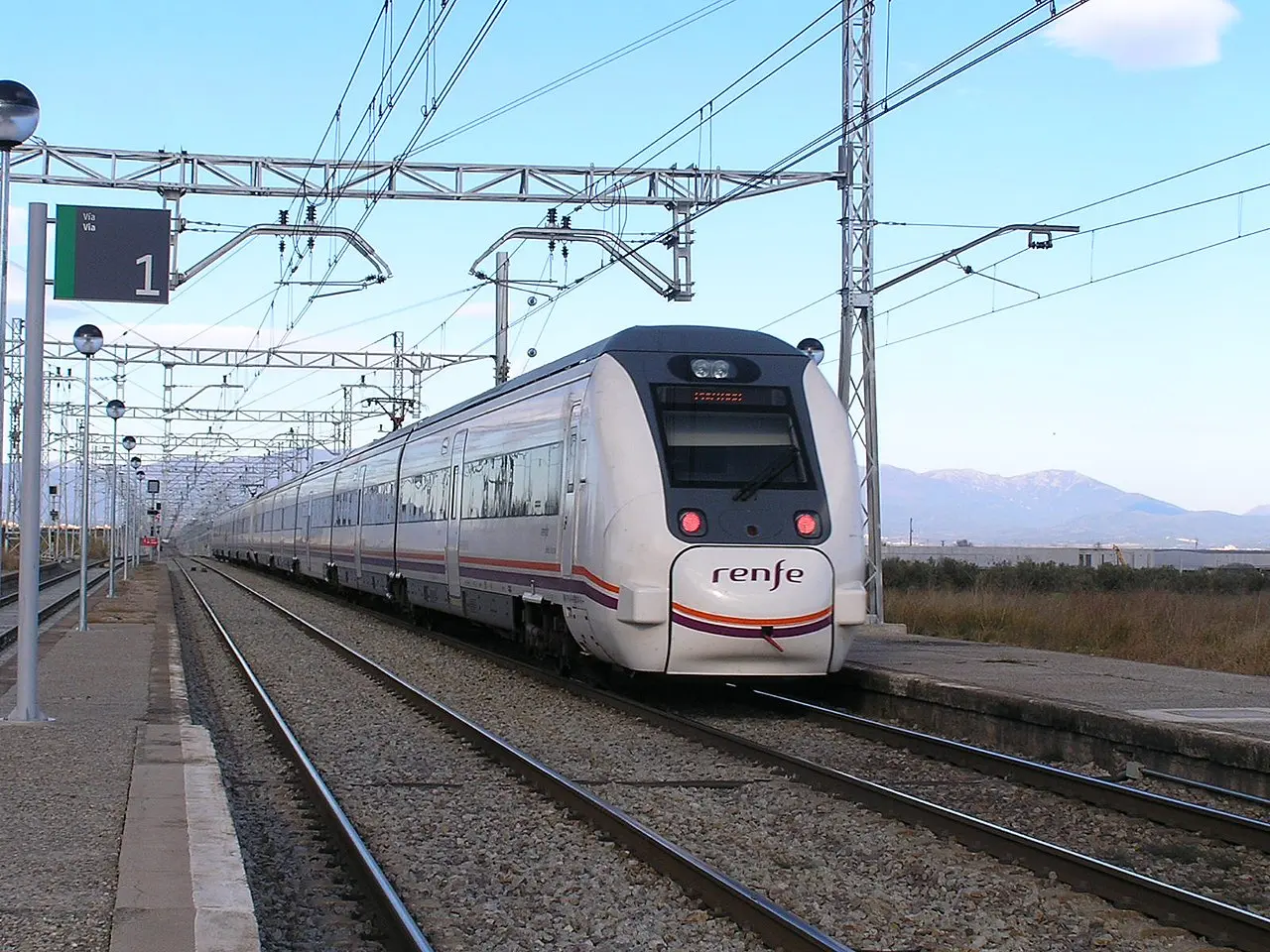
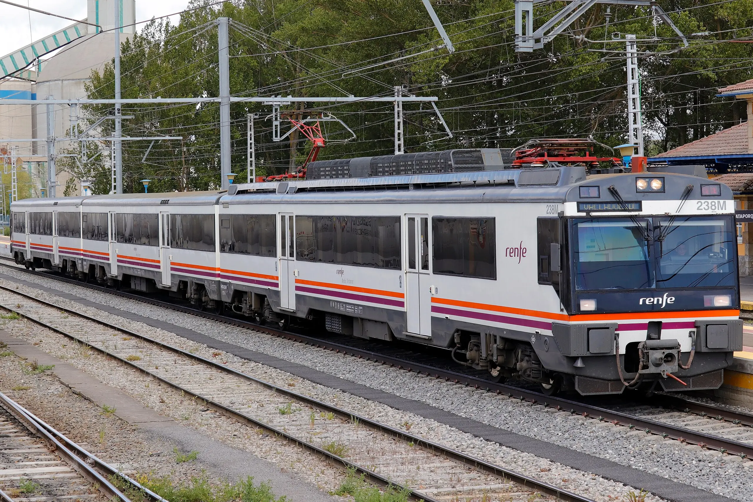
Operational characteristics of medium-distance services include:
- Typical journeys of 150-400 km with intermediate stops in regional cities
- Seating configuration with higher proportion of first-class seats relative to commuter services
- Basic catering services available in some cases
- Traction systems optimized for performance at speeds of 120-200 km/h
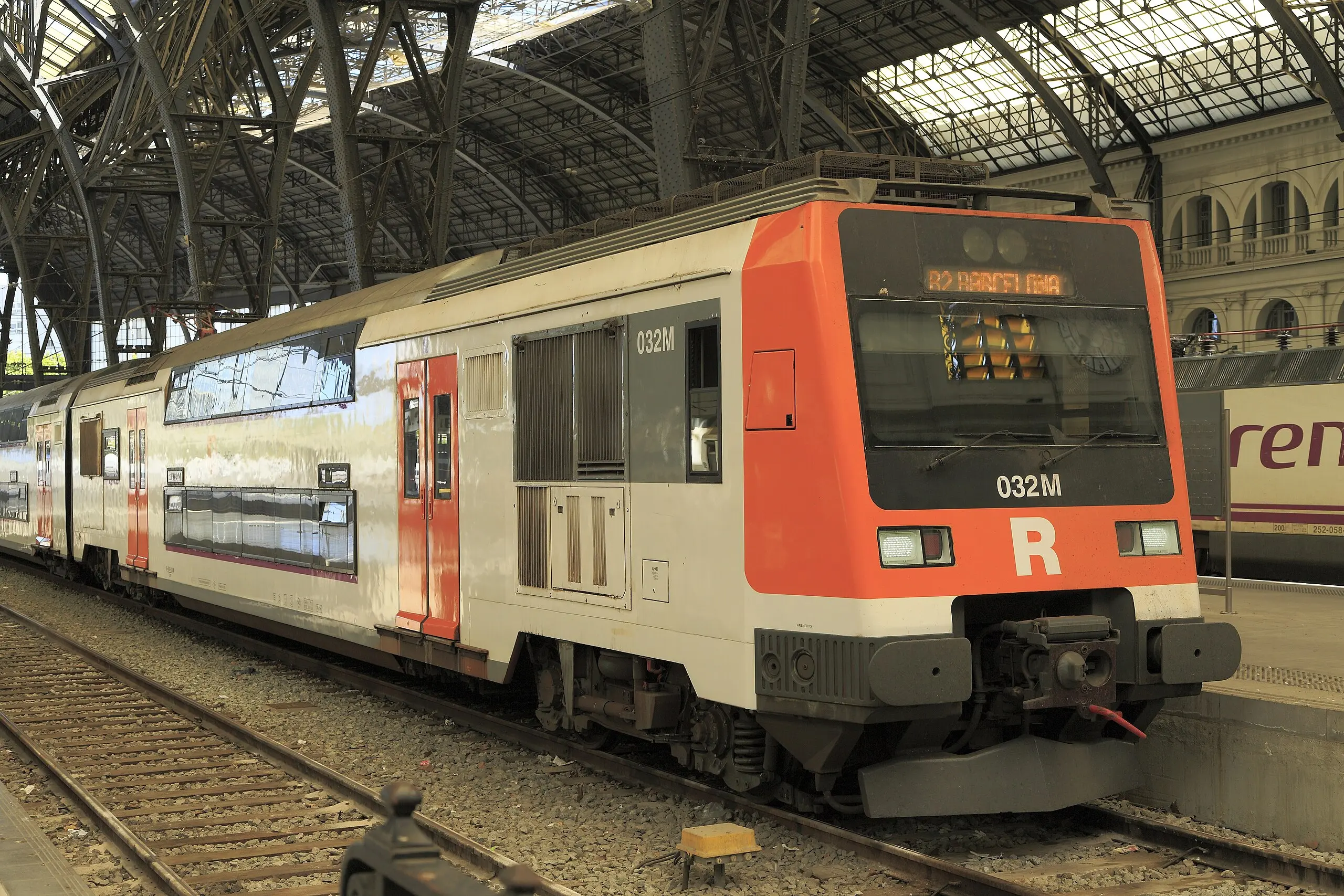
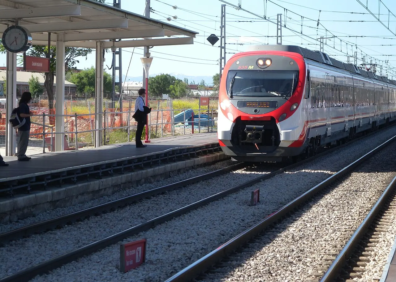
XIV.2.5. Commuter Systems (Cercanías): Massive Metropolitan Transport Infrastructure
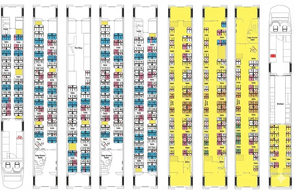
Commuter services constitute the backbone of mobility in Spanish metropolitan areas, providing high-capacity transport for short-distance trips (typically 10-80 km). The Civia series and its variants represent the fundamental solution for this operational function:
Civia (S-462) - Base Metropolitan Transport Platform
The Civia series, officially designated as S-462, constitutes the fundamental architecture of commuter transport in multiple Spanish metropolitan areas:
Fundamental operational characteristics:
- Distributed traction: Traction motors installed in multiple bogies distributed along the composition, optimizing available power and reducing centralized maintenance
- Passenger capacity: Approximately 880 passengers in standard 4-coach composition
- Integral low floor: Floor height of 550 mm throughout the vehicle extension, eliminating architectural barriers for persons with reduced mobility
- Acceleration/deceleration systems: Rapid acceleration and braking capacity required for high-frequency operation with multiple stops per hour
- Multiple doors: Configuration of wide and frequent doors to minimize dwell times
XIV.2.6. Regional Commuter Variants: Specific Adaptations by Metropolitan Area
The success of the Civia platform has allowed the development of multiple variants adapted to specific requirements of different operators and railway systems:
Main variants include:
- Civia Standard Renfe: Base version operated mainly in Renfe with 4-6 coach configuration
- Civia Bilbao (Euskotren): Special adaptation for operator Euskotren in the Basque Country, incorporating regional signaling and control specificities
- Civia Angled Variants: Subsequent aerodynamic redesign improving energy efficiency and visual aesthetics
- Metric Gauge Adaptations: Platform extensions for metric gauge lines (1000 mm) in specific regions
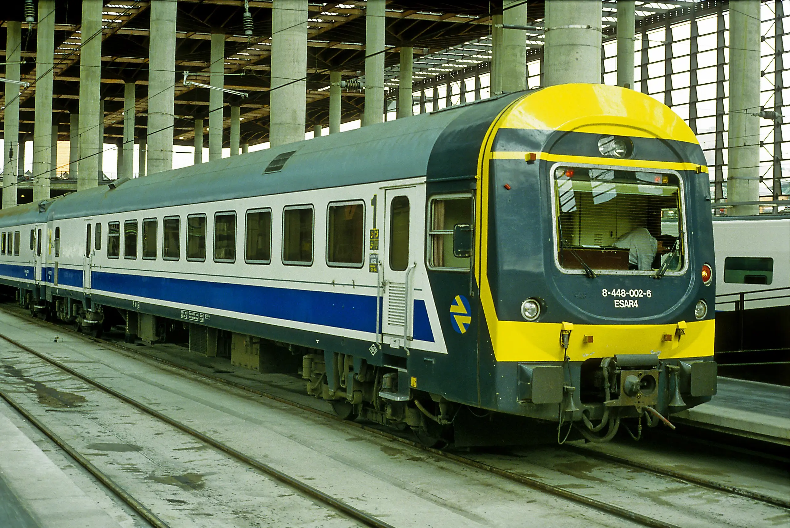
XIV.2.7. Series S-447: Specialized Alternative Commuter Compositions
Beyond the Civia family, there are complementary compositions designed for specific commuter functions:
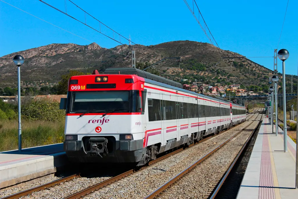
The S-447 series and its variants provide:
- Alternative passenger capacities (typically 600-750 in shorter length compositions)
- Specialized interior configuration options for different demand profiles
- Traction and braking systems optimized for specific lines with particular geometric characteristics
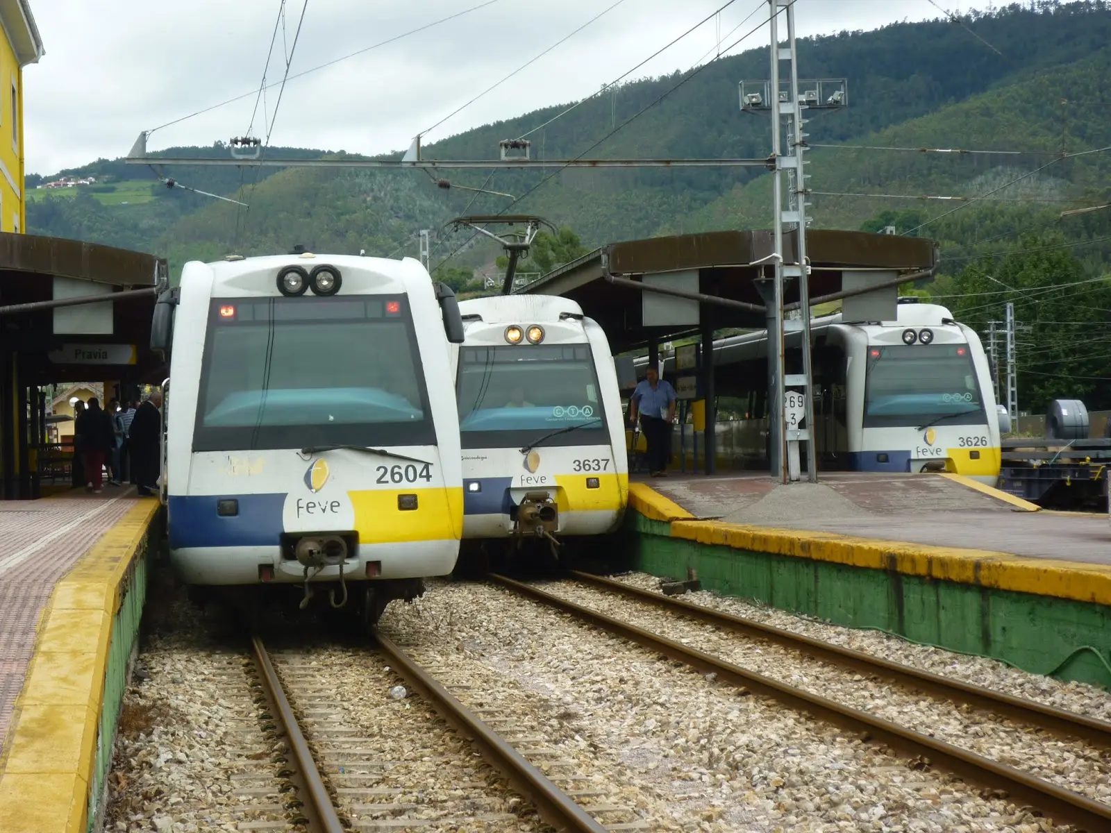
XIV.2.8. Metric Gauge Transport: Solutions for Specialized Lines
Spanish metric gauge lines (1000 mm), although limited in extent, require specialized compositions adapted to these more restricted gauges:
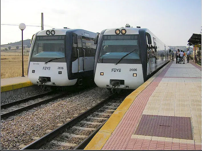
UTDH-2600 - First Generation of Metric Diesel
The UTDH-2600 series constituted the first generation of metric gauge diesel train units, providing regional transport solutions for lower volume lines:
Operational characteristics:
- Diesel-hydraulic traction optimized for steep gradients on mountain lines
- Reduced capacity compared to standard gauge systems (typically 150-200 passengers)
- Flexible configuration for passenger services and small freight volumes
UTDH-2900 (Bi-cab) - Second Generation with Double Driving Cab
The UTDH-2900 series represented a significant evolution, incorporating two driving cabs (allowing operation without locomotive turnaround at terminals) and modernized systems:
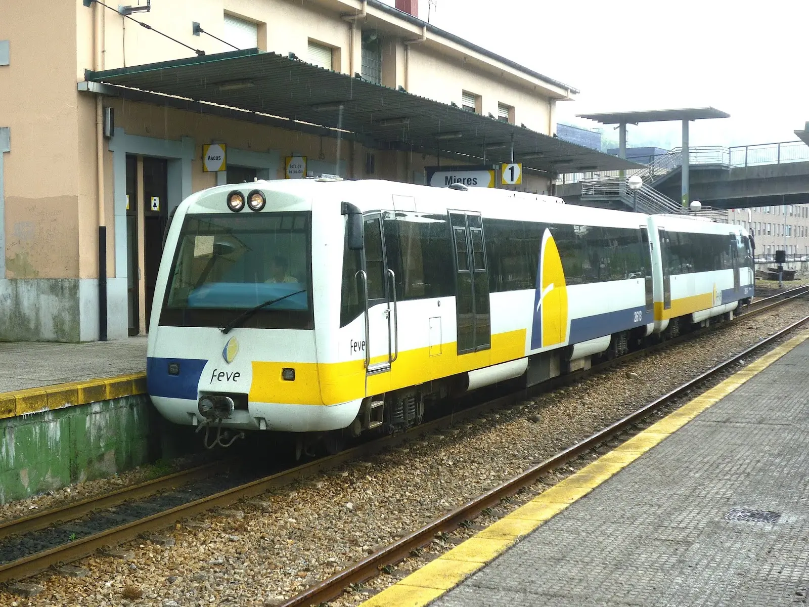
Operational improvements include:
- Double driving cab for terminal efficiency
- Improved braking systems with regeneration where possible
- Automation of operational processes reducing personnel requirements
- Significant improvement in passenger comfort compared to previous generation
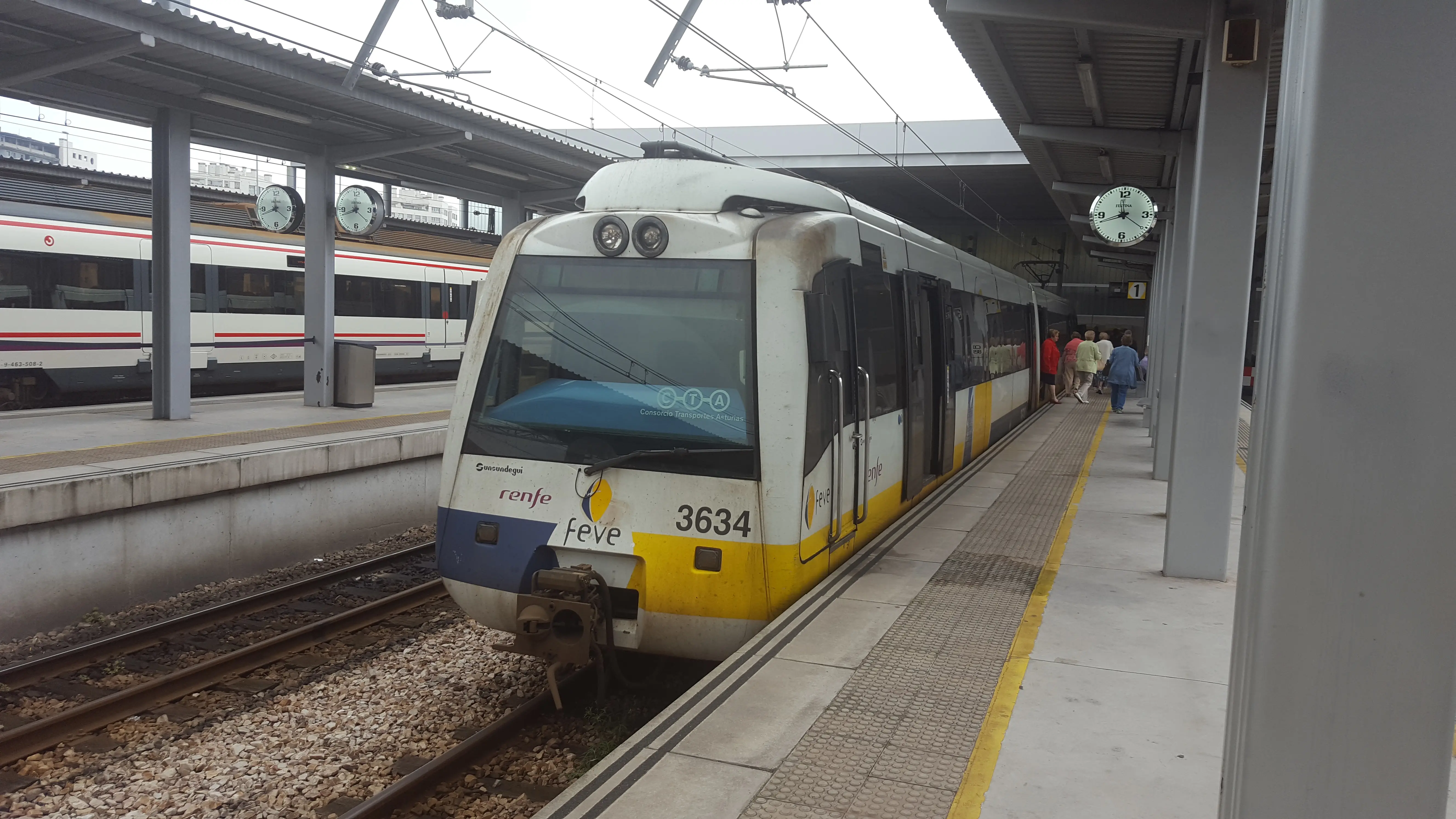
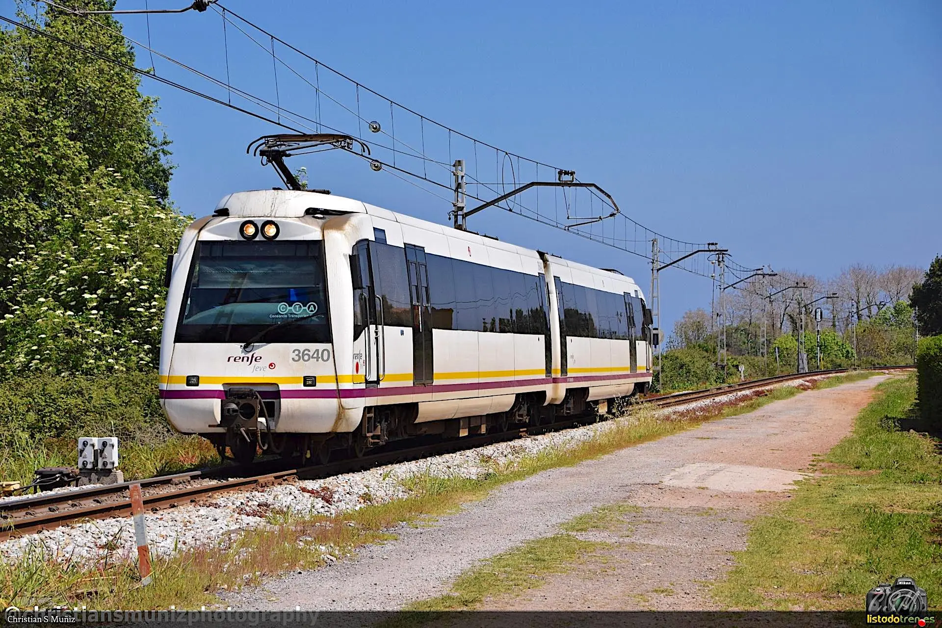
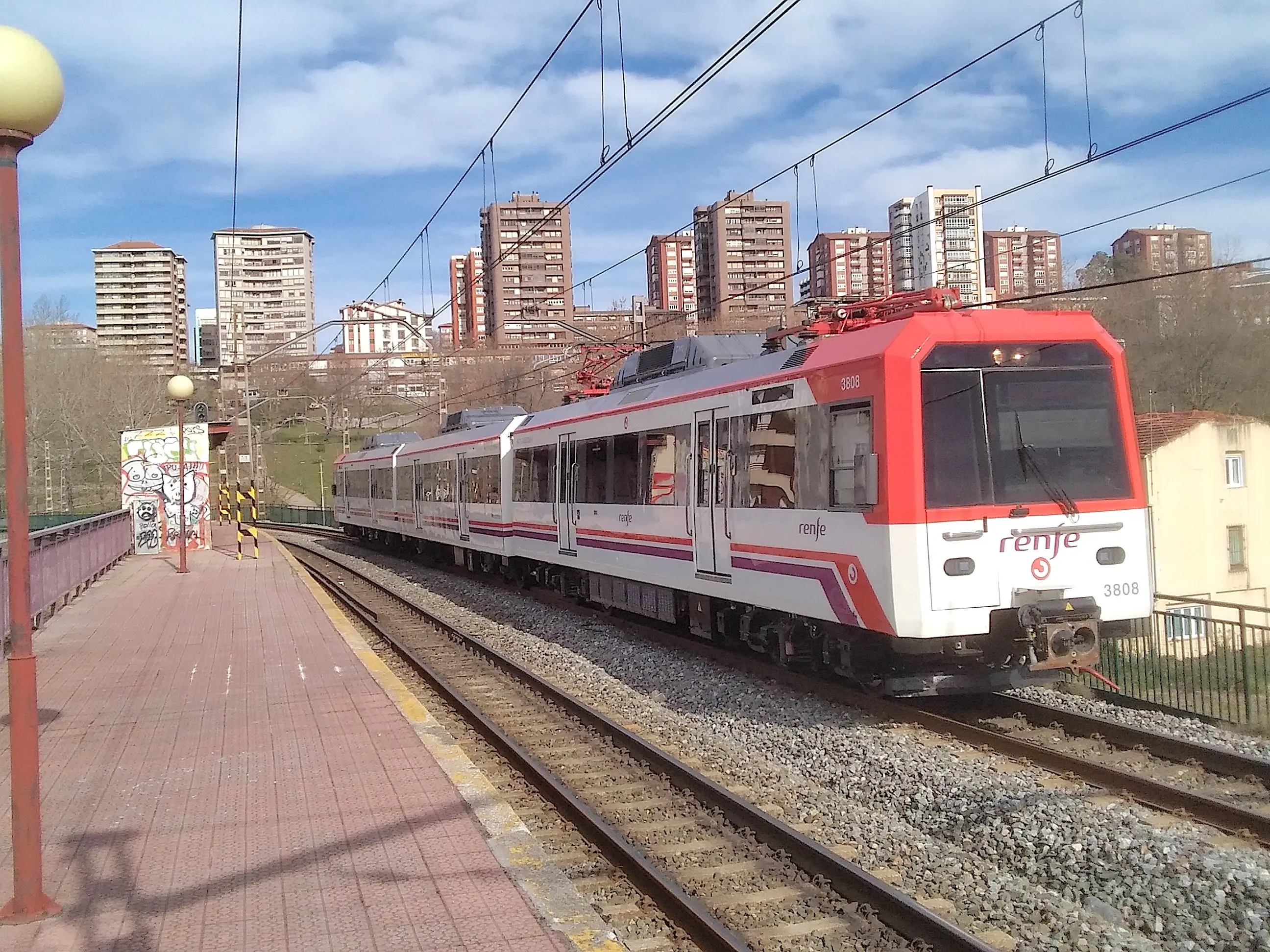
UTE-3800 and UTE-3600 - Modern Electric Traction Generations
For electrified metric gauge lines, the UTE-3800 and UTE-3600 series provide clean energy solutions:
- UTE-3800: Modern alternating current electric traction system, providing maximum energy efficiency and advanced regeneration capabilities
- UTE-3600: Optimized variant with flexible composition configuration, allowing adaptation to specific volume and frequency demands
Both series incorporate:
- Three-phase asynchronous traction systems
- Improved acceleration and braking capabilities compared to diesel
- Control interfaces compatible with European signaling systems
- Integral low floor facilitating barrier-free access
Review Questions
What is the fundamental difference between concentrated traction trains and distributed traction trains?
In concentrated traction, motive power resides in independent locomotives; in distributed traction, motors are distributed throughout motor coaches in the composition (e.g., Civia, Alaris).
What advantages does railway electrification offer versus diesel traction?
Higher energy efficiency, absence of local emissions, lower long-term operational costs, and better acceleration capability.
What main function does the “bogie” perform in a railway vehicle?
It is the dynamic support structure housing axles and wheels, allowing curve inscription, carbody suspension, and (in motor vehicles) traction transmission.
What characteristic defines “schnabel” freight wagons?
Their design with a beak shape for transporting extraordinary loads of great weight and dimension, allowing maximum utilization of available gauge.
What is the dynamic gauge in the railway context?
The maximum geometric envelope occupied by a moving vehicle, integrating its constructive profile, suspension displacements, curves, cant, and safety margins.
Bibliography
The present technical documentation has been developed based on academic references, railway operation regulations, and technical specifications from recognized manufacturers in the sector:
- Fernandez Undabarrena, P.I. (2022) Prestaciones del Materia Rodante. Apuntes del Máster en Ingeniería Ferroviaria. Universidad de CantabriaMafex.
- García Álvarez, A. (2022) Manual de ferrocarriles. El sistema ferroviario español. Ed. Garceta.
- Villar, R. (2022) Clasificación Material Rodante. Apuntes del Máster en Ingeniería Ferroviaria. Universidad de Cantabria-Mafex.
- https://www.renfe.com/es/es/grupo-renfe/grupo-renfe/flota-de-trenes
- Casas, J.C. et al. (eds.) (2022) Historia del ferrocarril en España. Madrid: Fundación de los Ferrocarriles Españoles.
- Trenes y tiempos. Un paseo histórico, anecdótico y un punto sentimental por nuestros trenes