Railway Stations: Infrastructure and Operation
Table of contents
Chapter I. Definitions
A railway station constitutes a fundamental component of railway infrastructure, defined as the place where various operations linking the railway with other existing modes of transport are executed. In the context of external services, intermodal connection is facilitated, while in internal services, operations inherent to railway operation are performed. From an infrastructural perspective, a station comprises an integrated set of installations, among which railway tracks and turnout systems stand out, enabling the orderly and safe movement of railway compositions, as well as the movement of passengers and freight, optimizing both operation times and employed resources.
Within these facilities, complex and varied operations take place: loading and unloading of goods proceed with the manipulations this entails, passenger boarding and alighting is managed, necessary maneuvers for the reorganization of compositions are executed, train circulation through different routes is established and coordinated, and a good part of the operational activities of the railway system are developed. Due to this multiplicity of functions and operations that a station houses, it is particularly challenging to formulate a definition that exhaustively encompasses the totality of processes developed therein.
From a broader functional perspective, the railway station represents the integral structure of an organizational system encompassing different traffic subsystems specifically adapted to passenger and freight transport modalities. These subsystems are conventionally known as terminals, each specialized in its particular function. Depending on the nature of the traffic they manage, these terminals are classified into two main categories: passenger terminals and freight terminals.
In the contemporary evolution of railway infrastructure, a marked trend towards functional specialization is observed. Thus, traditional stations that historically attended combined passenger and freight traffic simultaneously have undergone a reconversion process, progressively transforming into specialized passenger traffic terminals. Concurrently, the creation of terminals specifically designed and dedicated to freight movement has been promoted, allowing for operational optimization and better adaptation of each infrastructure to the particular requirements of its traffic modality.
In the realm of station infrastructure, track is understood as each of the discrete sections of railway line possessing a specific operational function and predetermined extension. The functional classification of tracks within a station responds to the nature of operations executed on them. Various categories can be identified: running tracks (vías de circulación) constitute the main conduits from which compositions proceeding from other sections are received or from which trains are dispatched towards their destinations; siding tracks (vías de apartado) allow the temporary withdrawal of compositions from running tracks when necessary; reception and dispatch tracks are dedicated specifically to incoming and outgoing train movements; stabling tracks serve as resting areas where compositions remain awaiting new instructions or operations; there are also tracks dedicated exclusively to freight loading and unloading operations; finally, sorting, formation, and marshalling tracks fulfill logistical reorganization functions, allowing the constitution of new compositions and the classification and ordering of trains and wagons according to their destinations and characteristics.
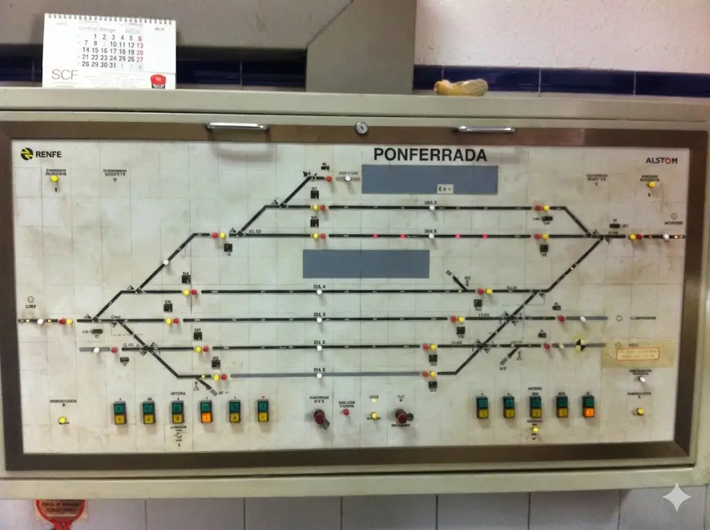
Considering operational relevance within the station system, hierarchical categories can also be established: general tracks (main lines) represent a continuity of the main railway route within the station area and frequently function as through tracks that trains traverse without stopping; main tracks constitute the axes of highest use intensity and typically have associated platforms for passenger operations; secondary tracks encompass the rest of linear installations. To guarantee fluid circulation of railway compositions and enable necessary route changes, the installation of transition and connection structures, known as crossings and crossovers (escapes de unión), properly linking the various track sections, is indispensable.
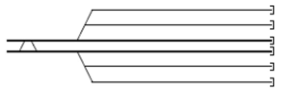
Within turnout configurations destined to interconnect parallel tracks, three main types of transversals (ladders) stand out. The lateral transversal (simple ladder), also called diagonal or haz, constitutes an articulated set of turnouts organized such that derived branches succeed sequentially on the diversion of the first turnout. This configuration is characterized because the initial turnout possesses a different orientation regarding the others, although all share the same approach tangent. This type of transversal is particularly appropriate for connecting parallel tracks.

The fan-shaped transversal constitutes an alternative for connecting parallel tracks, employing turnouts that possess the same orientation (hand), forming a configuration analogous to the ribs of a fan.
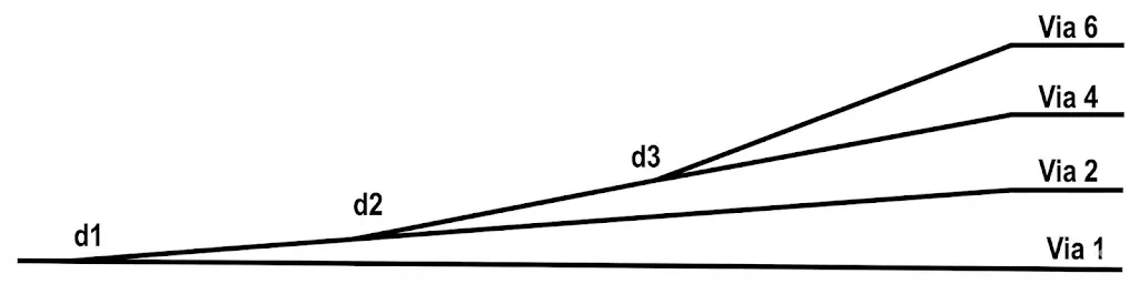
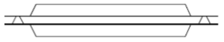
On its part, the central transversal differs by the uniformity of its components: all turnouts are identical, possessing identical tangent and identical hand, thus allowing a symmetrical and balanced configuration that is also dedicated to joining parallel tracks.
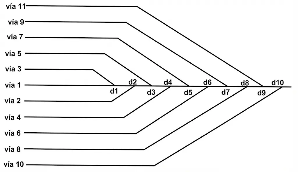
In the operational practice of station design, the combination of multiple turnout types is frequently required to achieve complex functional configurations that optimize train circulation and available space utilization. The following illustration presents examples of such combinations:
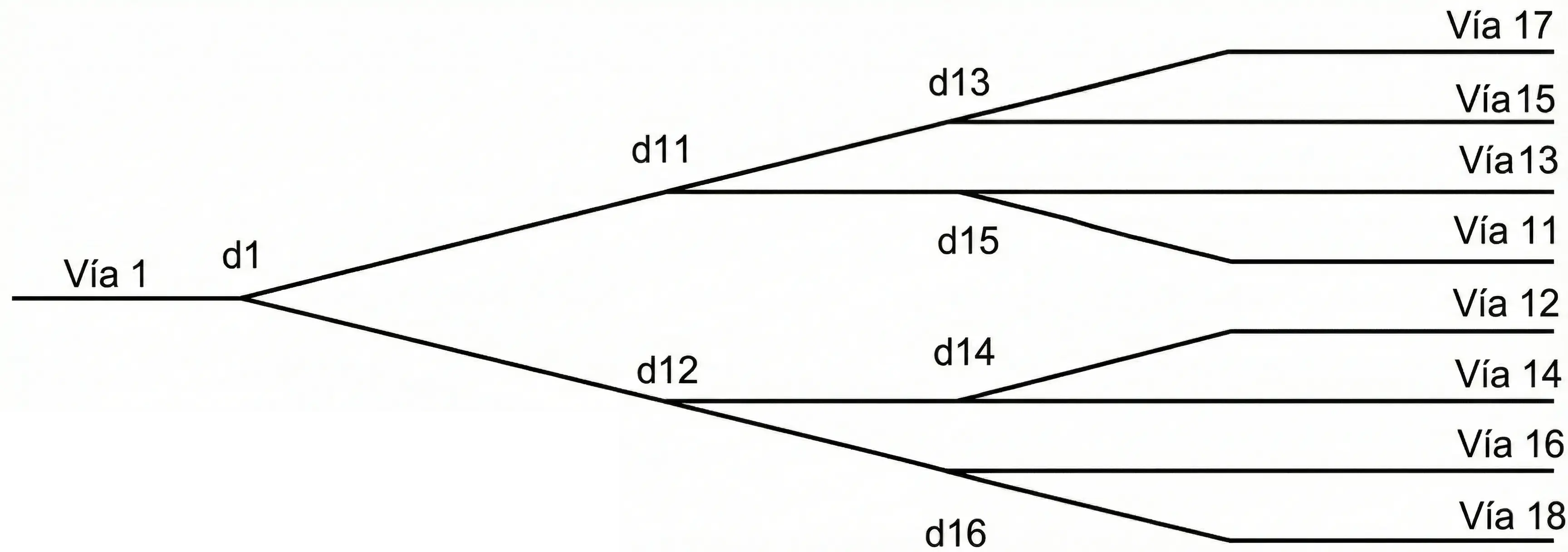
In these examples, the arrangement d1, d12, d16 constitutes a diagonal configuration, while the combination d1, d12, d14 together with d1, d11, d15 forms a fan-shaped structure.
I.1. Parts and functions
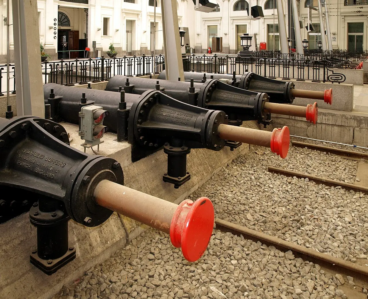
For an integral understanding of station composition, it is essential to identify its fundamental components. From a railway perspective, constituent elements include platforms facilitating passenger access, the specific configuration of track number and layout determining operational capacity, and mechanisms regulating train traffic through predetermined routes. Support installations encompass critical elements like buffer stops or end-of-track buffers guaranteeing safety, turnout systems allowing composition maneuvering, and railway signaling coordinating movements.
From a broader structural perspective, the railway station functions as the integrated organizational structure of a system constituted by specialized traffic subsystems for passenger and freight movement, conventionally designated as terminals. These terminals differ functionally according to the traffic modality they serve: there are terminals specifically oriented to passenger traffic and terminals dedicated to freight movement, each optimized for its own operational demands.
Track End and Buffer Stop
Each railway station project presents singular and unique characteristics, responding to specific operational needs. There is no standard mass construction model; on the contrary, each installation is projected and constructed as a particular solution to fulfill a determined function. By way of illustration, one can mention the case of halts/stops destined for commuter services in specific urban nuclei, or specialized loading points for mineral or particular material operations coming from quarries. The dimension, form, and general configuration of a station are invariably defined through a design process responding to concrete missions and particular operational requirements.
During the station design process, numerous technical variables require careful and coordinated consideration. Among the most relevant are the determination of track section length and railway superstructure specification, appropriate selection of turnout systems considering their geometric and tangent characteristics, definition of transverse spacing between tracks (track centers) according to functional requirements, and platform design in terms of height, length, and capacity.
A notable engineering aspect in station design is the consideration of the installation’s relative elevation or grade. When a station is situated at an elevated grade relative to the surrounding terrain, railway compositions arriving at it can partially convert their kinetic energy into gravitational potential energy, reducing energy dissipation through braking systems. This strategy not only optimizes energy consumption by decreasing braking system demand but also allows for reducing energy demand peaks required during composition startup and acceleration phases. Additionally, in the case of stations designed with underground configuration, relative elevation contributes to minimizing the height required for vertical communication structures, thus improving the project’s economic viability.
As an illustrative example, consider a commuter station projected with a relative elevation of 3 meters regarding the local reference level. This configuration allows achieving significant savings in various operational and construction aspects:
I.2. The Tracks
The operational conception of each track performing within a station is directly linked to a specific function, implying that both its location within the station configuration and its longitudinal extension must faithfully correspond to the requirements of that particular function. The general track layout must be optimized such that train reception processes from the general network, their departure towards subsequent destinations, and their temporary parking require the least possible amount of maneuvering operations, thus reducing infrastructure occupation times and operational costs. The longitudinal extension of each track must be sufficient not only for a railway composition to be accommodated entirely within it but also to allow necessary movements and repositioning during the execution of specific operations for which that composition was directed to the station.
The determination of the required length for each track can be established relatively directly considering the length of trains that will use it. This approach can be illustrated by examples of different typologies: in metro systems, length typically corresponds to the extension of a complete train unit; in commuter services, it is frequently required to accommodate 3 units of 3 cars each, resulting in 225 meters considering a 25-meter module per car; in other traffic types, the length of railway compositions, spaces required for locomotive maneuvers, and loading or unloading operations to be performed must be jointly considered.
A fundamental concept in track configuration is the so-called clearance point or fouling point (piquete de entrevía). This represents a specific point located between two tracks converging towards a turnout, beyond which simultaneous circulation of compositions on both tracks becomes incompatible from an operational safety point of view, as compositions would collide with each other. The marker is situated at a uniformly defined distance from both tracks; the Spanish railway administration (ADIF) conventionally establishes this distance at 1 meter. The existence of the clearance point entails a loss of useful track, that is, of usable length for railway operations. The extension of useful track lost due to the presence of the clearance point, designated as Lp, can be calculated by:
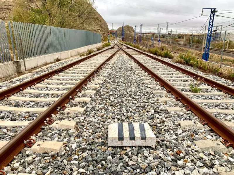
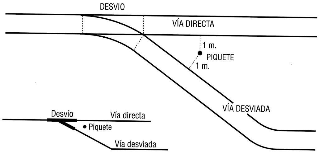
The useful track length constitutes a critical parameter in the operational characterization of station tracks. It is defined as the longitudinal track section which, in the context of a railway station, can be employed safely and effectively for movement and parking operations of compositions. It is important to note that in the calculation of useful track length, sections occupied by turnouts situated within the track are not included, nor are intermediate sections comprised between turnout points and clearance points previously described. This distinction is important for performing precise evaluations of available operational capacity.
The following illustrations present graphic examples of track configurations and the determination of useful tracks in different station contexts:
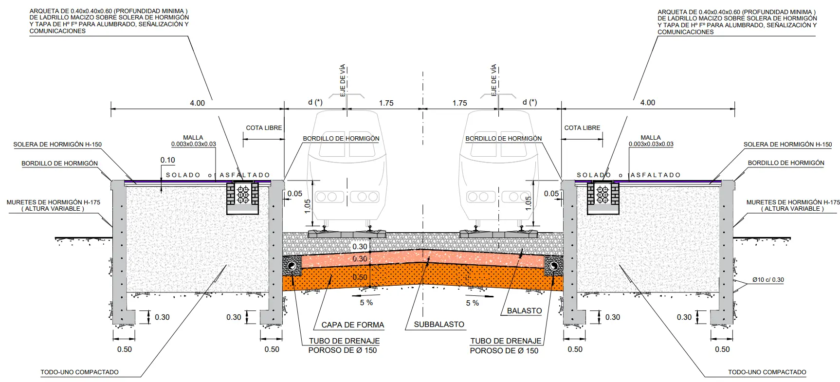
I.3. Track Centers (Entrevías)
Track centers (entrevías) constitute fundamental elements in the operational functionality of a railway station, largely determining its dimensional characteristics and logistical efficiency. The specific function assigned to each inter-track space directly determines its width or spacing, which significantly impacts the general transverse dimension of the entire station installation. For this reason, track centers represent critical and determining factors in the final dimensional configuration of a station.
It is important to distinguish between different types of track centers according to their specific function. Circulation track centers constitute the necessary spacing between parallel tracks to allow railway compositions to transit simultaneously on both tracks maintaining adequate operational safety standards. This magnitude is directly proportional to circulation speed: the higher the operation speed, the greater the required spacing to guarantee safety. Platform track centers are determined by the dimensions of the platform itself, varying according to station typology: in small stations, platforms with widths of 2 to 3 meters are contemplated, while in stations of higher traffic volume, they are typically expanded to 4 to 6 meters. There are also personnel track centers, that is, spaces that must be specifically reserved to allow railway staff to perform their operational functions, including technical inspections, brake system verifications, maneuver accompaniment, and other maintenance and supervision tasks. Finally, track centers destined for loading operations must be specifically dimensioned based on the type of loading operation to be executed in that sector of the station, considering required machinery and spaces.
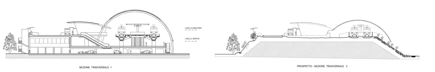
 image-28.webp)
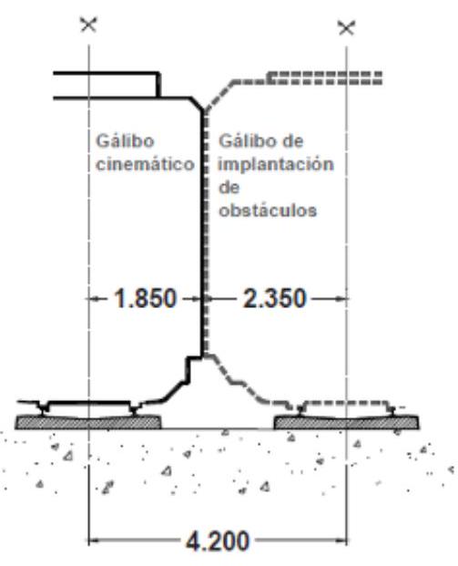 Case 1: Without posts in the track center
Dimensions in millimeters
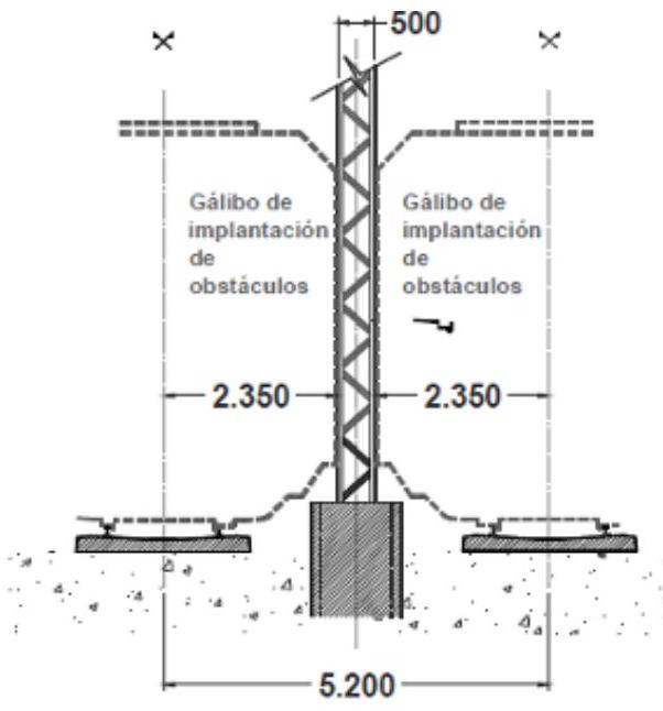 Case 2: With posts in the track center
Chapter II. Passenger Stations
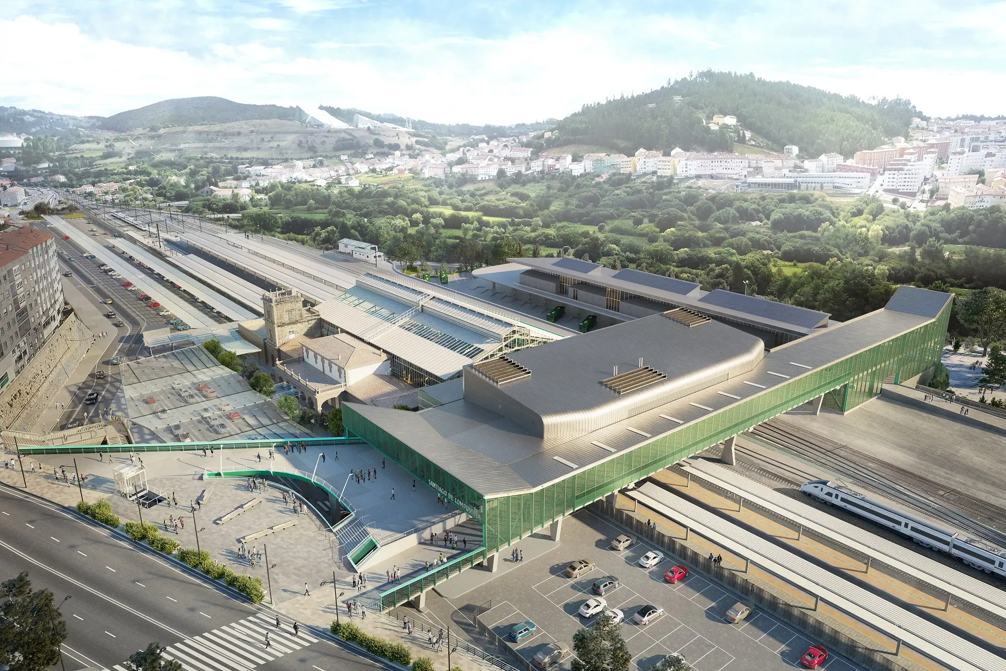
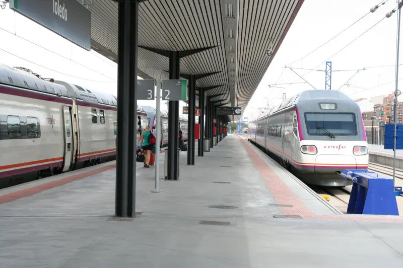
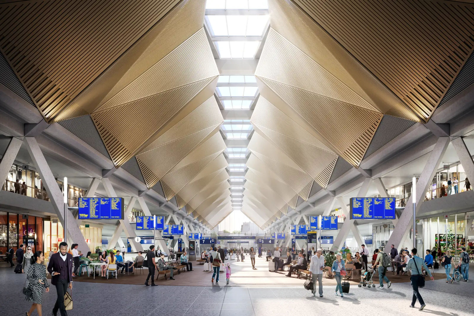
A railway passenger station can be characterized as a space of modal transfer and exchange, where operational connection between railway infrastructure and various complementary transport modes is facilitated. These facilities perform crucial functions of concentration and dispersion of passenger flows, facilitating orderly access of users to the railway system and their egress towards other means of transport or final destinations.
In structural terms, a passenger station typically comprises three fundamental components. Firstly, railway installations proper, encompassing track configuration, platforms, inter-track spacing, turnout systems, shunting yards, interlocking and blocking systems, communication infrastructures, signaling systems, and the control center from which operations are coordinated. Secondly, the service building or terminal, housing administrative and commercial functions, including ticket offices or points of sale, check-in services, vertical and horizontal communication infrastructures to facilitate user movement, and complementary spaces. Finally, general accesses, comprising approach roads, vehicle parking areas, and intermodality spaces where different transport modes converge.
II.1. Types of stations by their position in the network
The typology of a passenger railway station is primarily defined by its position within the general network of railway transport. This position conditions the operational configuration, functional design, and modal exchange capacity the installation can offer. The following illustration synthesizes the main categories:
II.2. Dead-end Station (Terminal)
This type of station configuration corresponds to those facilities located at the end of a railway journey, without line continuity beyond the station. This layout conditions the infrastructure, requiring composition reversal systems for return. The following schematic representation illustrates this typology:
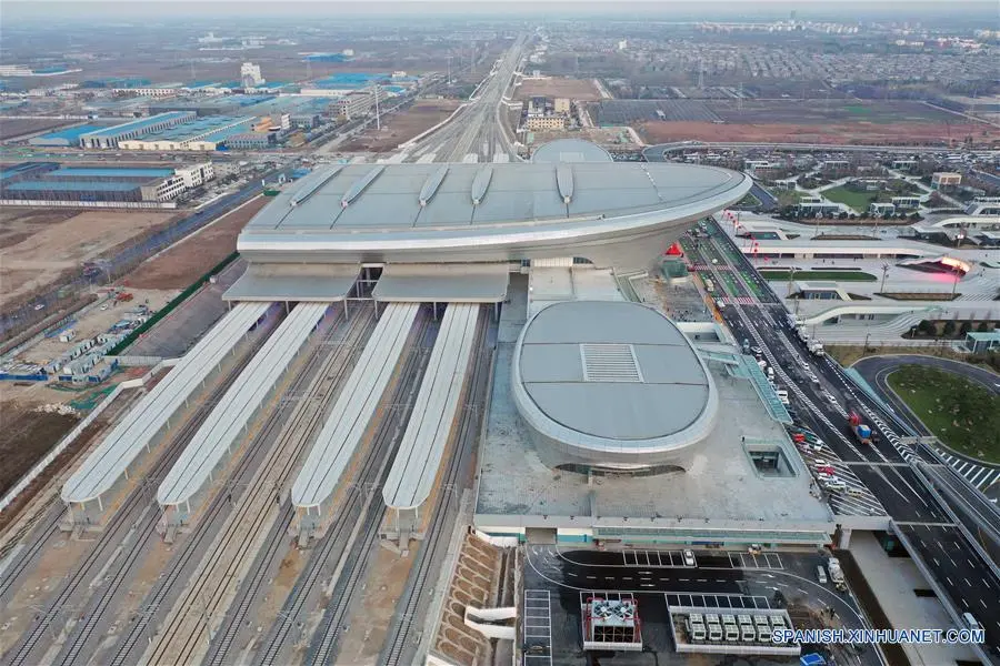
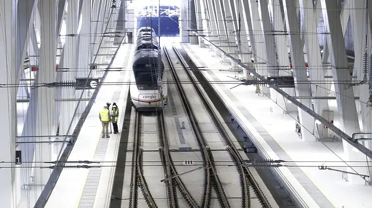
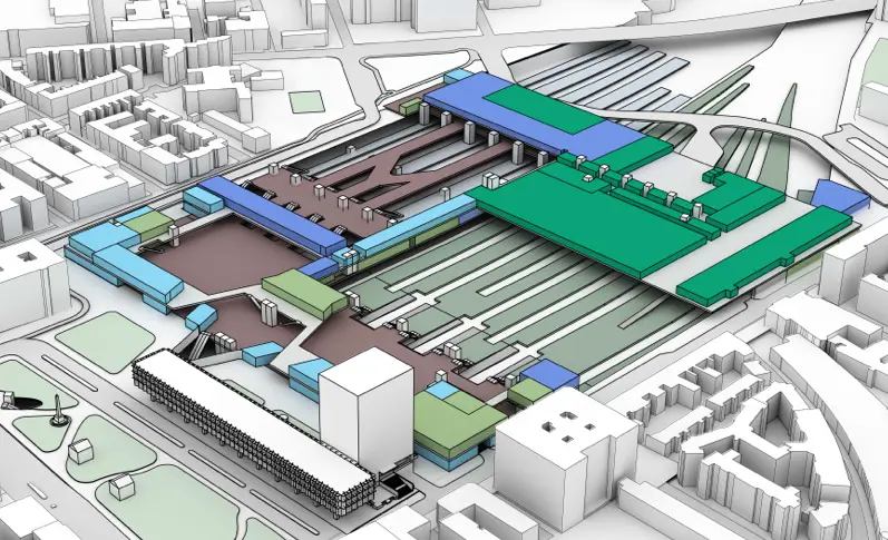
II.3. Through Station
The through station constitutes that facility located along a railway route, allowing line continuity and passage of compositions without need for interruption. This type of station presents superior operational complexity and requires careful coordination of diverse functions.
The functions a through station must fulfill are multiple and interconnected. Firstly, it must facilitate and guarantee fluid circulation of railway compositions through its influence area, as well as allow all necessary maneuvers for reordering and reorganization of trains. Secondly, it must provide safe, efficient, and comfortable access to travelers, facilitating their exchange with other complementary transport modes. It must also adequately manage passenger flows, both in terms of quantity and directionality, avoiding congestiones and ensuring orderly circulation. Finally, the station must be resolved architecturally and functionally in a way that harmoniously integrates with the surrounding urban fabric, minimizing negative impacts and maximizing connectivity with complementary urban services.
Main Line - Local Station in Central - High Speed Express Tracks - Tram/Light Rail Stops and Suburban Services
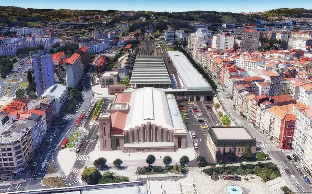
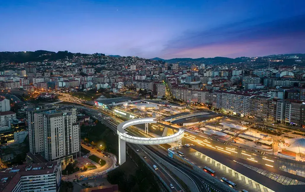
Many traditional railway stations have undergone remodeling and expansion processes in recent decades, responding to changes in operational demands and commercial considerations. These projects seek to improve functionality from a purely railway perspective, while enhancing commercial aspects and user attraction. In other cases, the introduction of new high-speed services has motivated significant adaptations and transformations of existing infrastructures; prominent examples include remodeling of stations like Madrid-Atocha or Barcelona-Sants. In additional situations, the construction of new stations in geographic locations distinct from traditional historic locations has been chosen, as occurred with Seville-Santa Justa and Zaragoza-Delicias, thus allowing integral design optimization without inherited restrictions.
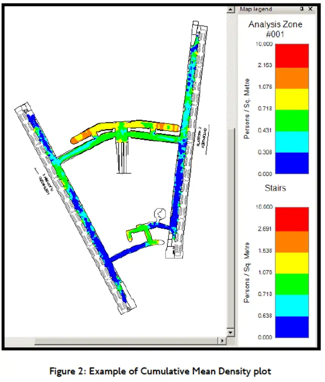
In through stations with multiple platforms, it is necessary to design communication systems allowing safe and orderly passenger movement between platforms. Normally, main access to the station is located on a single platform, implying that passage between platforms becomes an obligatory operation for all users wishing to access other platforms. This configuration requires special care in design, considering passenger flows and safety.
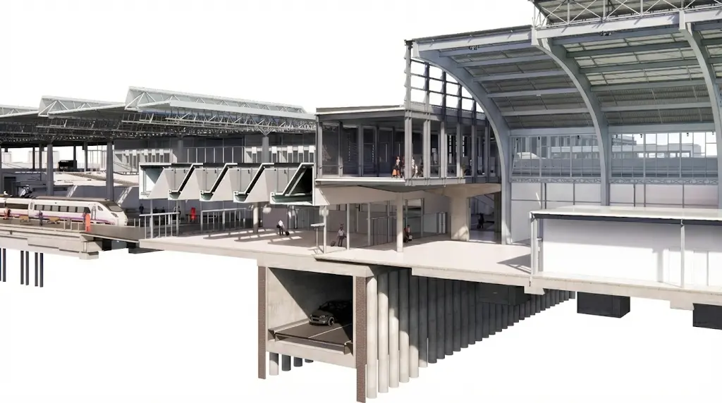
II.4. Types of passage between platforms
Infrastructures allowing passenger displacement between different platforms in a through station can be classified according to their geometric configuration and relationship with railway infrastructure elements. There are three fundamental typologies: level crossing, developed on the same plane as platforms; overhead crossing (footbridge), located longitudinally above track sections; and underground crossing (subway/underpass), excavated transversely under railway infrastructure. Each typology presents specific technical, operational, and economic advantages and limitations that must be evaluated in the context of the particular project.
The selection of passage typology significantly impacts the station’s vertical dimension, construction costs, accessibility for reduced mobility passengers, and pedestrian flow buffering capacity. Design must also consider the location of the vertical communications core (VCC), which can be situated both inside and outside the platform perimeter.
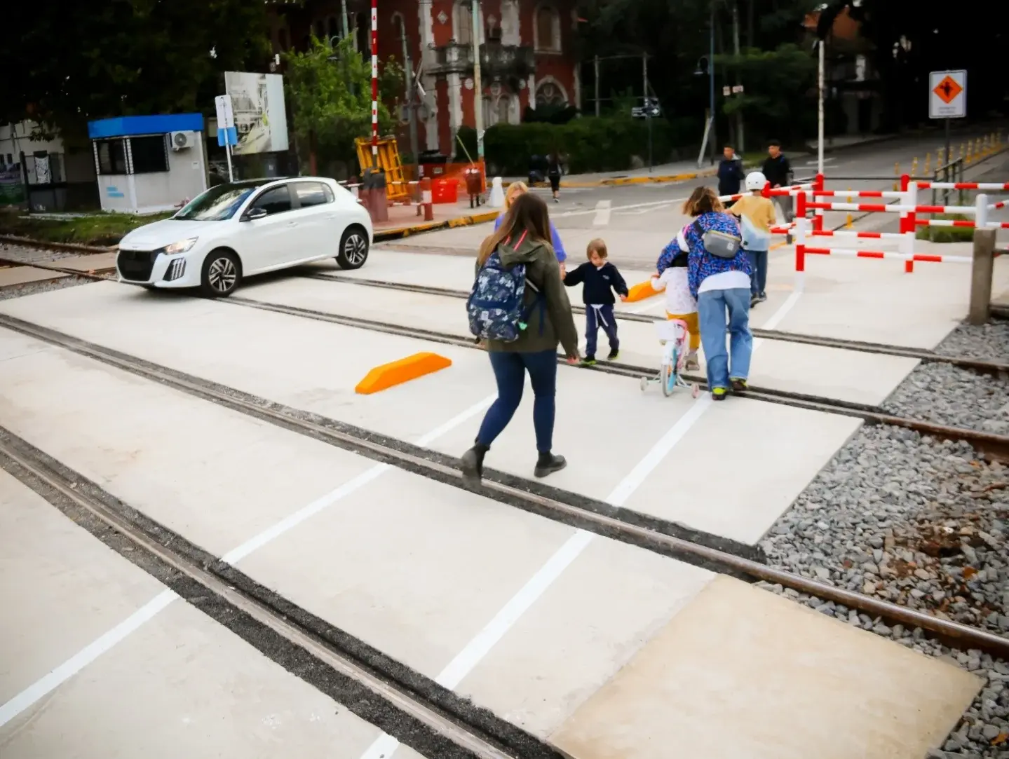 Level crossing
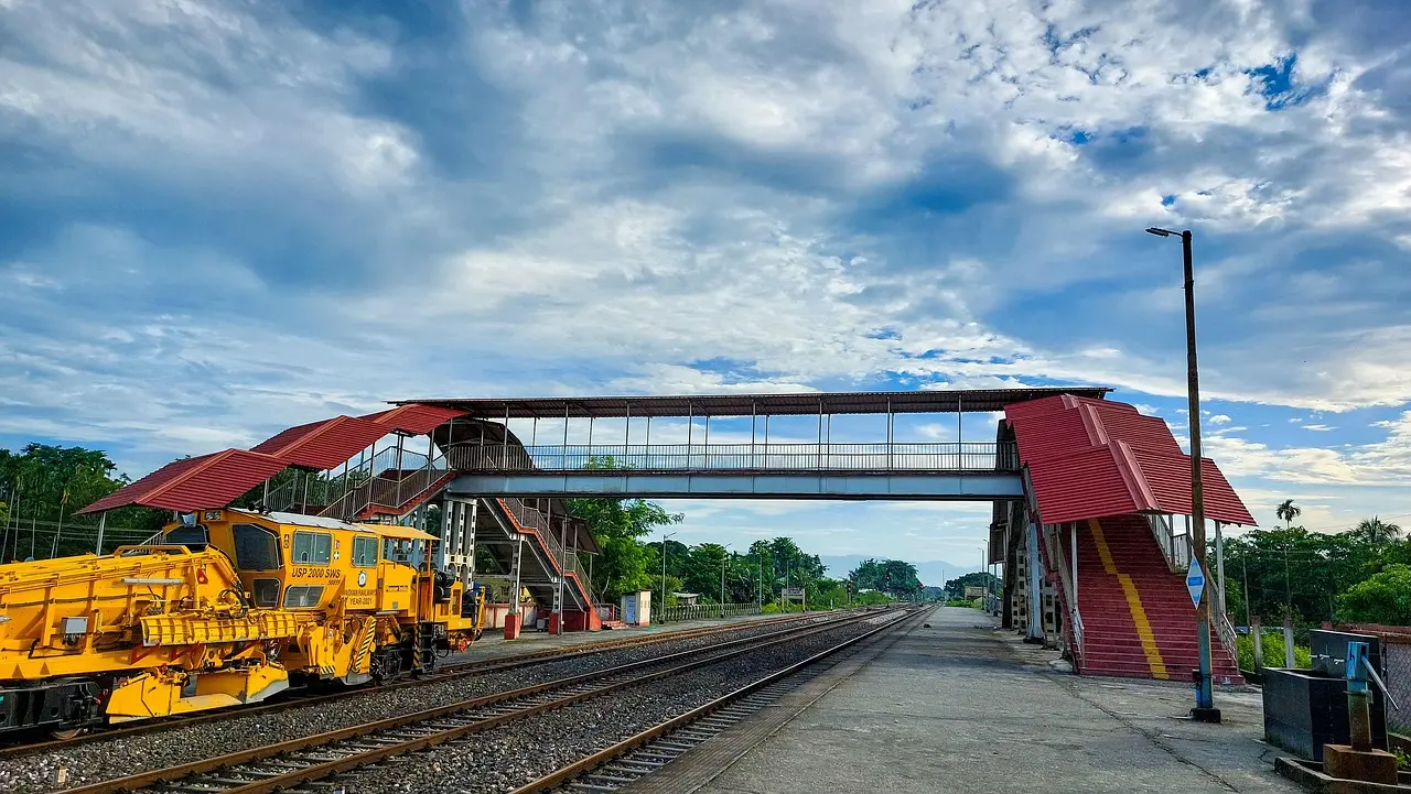 Overhead crossing
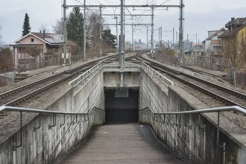 Underground crossing
(Dimensions in meters)
Underground crossing
(Dimensions in meters)
II.5. Platforms
Definition and function
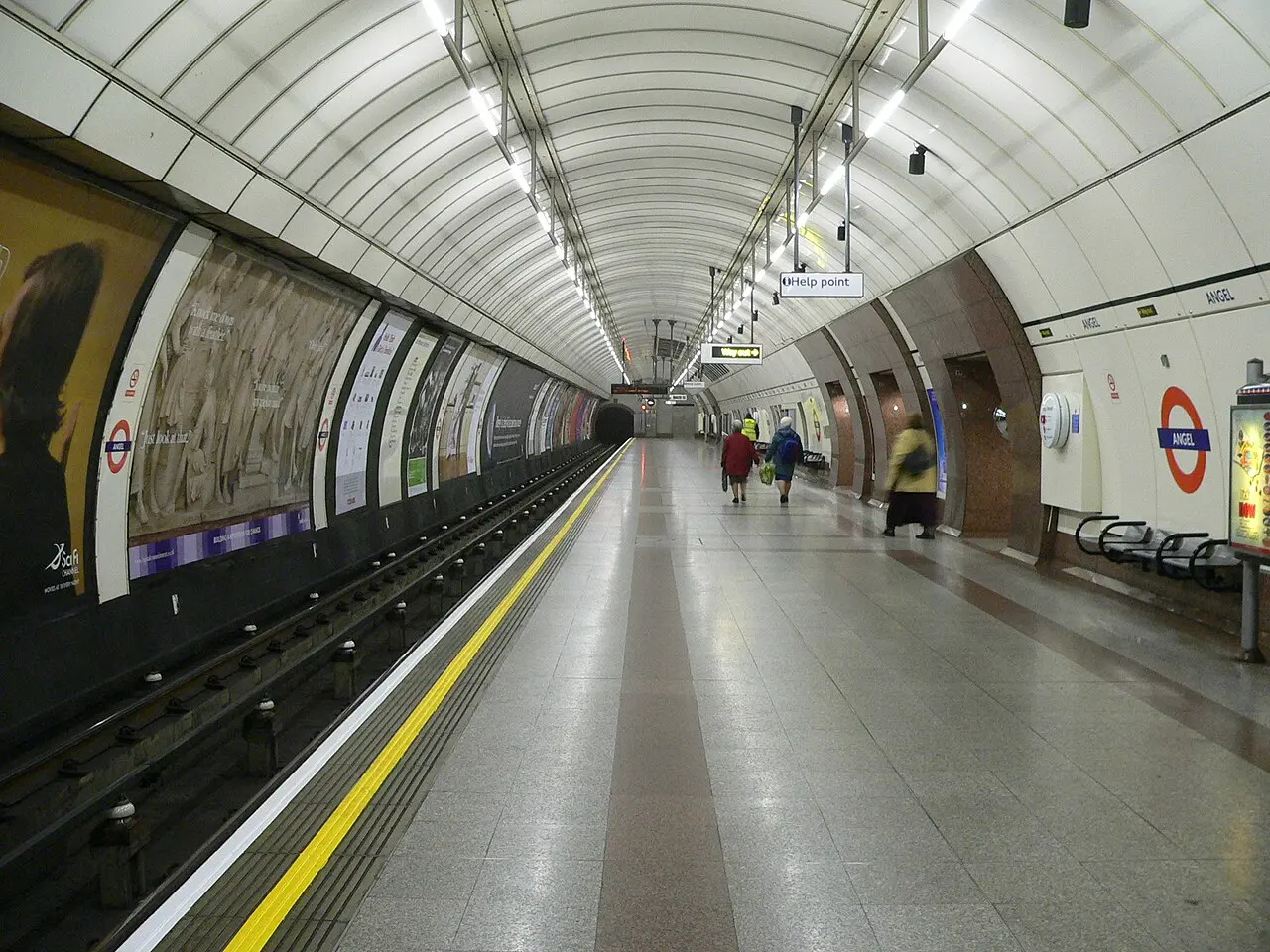
The railway platform is defined as the structured platform from which travelers transfer from firm ground or urban spaces to trains, as well as the inverse displacement from railway vehicles to ground level. This structure constitutes an essential element in any railway passenger transport facility, being fundamental for safety, comfort, and operational efficiency of transfers.
Design parameters: height
Platform height constitutes a critical technical parameter, defined as the vertical distance measured from the horizontal plane of the platform surface to the plane defined by the rail head. This parameter directly affects the vertical distance each passenger must overcome to access the interior of the railway composition. Specifically, the distance to be bridged by the user results from the difference between the train’s interior floor height (Hp) and platform height (Ha), considering also access steps that may exist inside vehicles. The difficulty level inherent in this vertical transfer significantly conditions times required for passenger boarding and alighting, directly impacting global station operation times. It is important to consider that current accessibility regulations impose restrictions on maximum heights and that track cant effects must be evaluated.
In the Spanish context, the railway administration (ADIF) establishes standardized platform heights according to station typology:
| Platform heights above rail head (on straight track) applied in Spain | |
|---|---|
| Station Type | Height (cm) |
| Multiservice Stations | \(55(+0,-0.3)\) |
| High Speed Stations | \(76(+0,-0.3)\) |
| Predominantly Commuter Stations | \(68(+0,-0.3)\) |
| Exclusively Commuter Stations | \(96(+0,-0.3)\) |
Platform edge detail according to NAP 1-2-1.0:
Technical platform without platform edge piece - Commercial platform with platform edge piece and surface finish
Design parameters: length
Platform length must be dimensioned, as a fundamental criterion, to accommodate the longest railway composition that will stop at it. However, when the composition exceeds available platform length, standardized operational alternatives exist: allowing placement of locomotives and vans outside the platform perimeter while all passenger wagons remain housed within it; performing parking in two sequential phases for boarding different passenger groups; when required, access doors of cars remaining outside platform perimeter can be locked. In any case, it is advisable to incorporate an additional safety margin in the total projected length. Typical standardized dimensions are: in commuter services, 250 meters (corresponding to 3 standard composition train units plus 25 additional safety meters); in high-speed services, 400 meters.
Design parameters: width
Platform width constitutes a parameter of extraordinary importance in station projects, as it simultaneously determines comfort and safety perceived by users during platform occupation and pedestrian transit processes, while also directly affecting territorial extension required for the installation. A platform’s cross-section need not be uniform, varying according to specific functions of each segment. Diverse technical factors must be jointly considered: minimum width determined by accessibility regulations for reduced mobility passengers; minimum safety distance required between waiting passengers and platform edges; dimension required to guarantee adequate fluidity considering passenger volume and density; necessary space to locate vertical communication cores and interconnection infrastructures, as well as shaded or protected waiting zones.
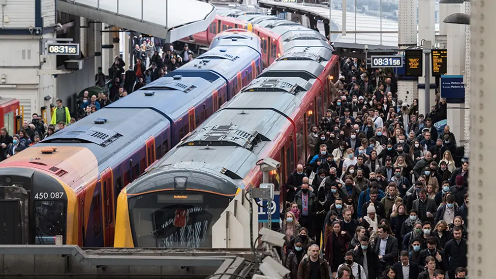
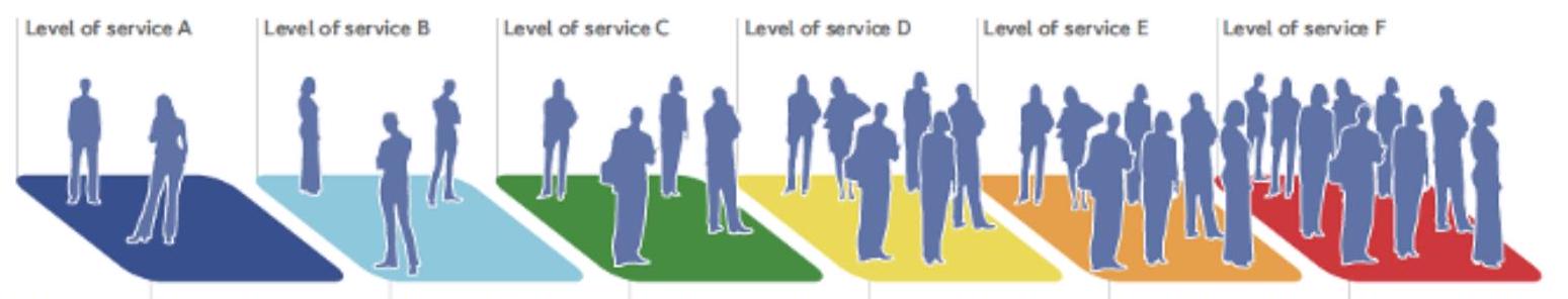
A conceptual framework frequently employed to evaluate pedestrian circulation capacity is the so-called “level of service”, classifying circulation fluidity according to relative congestion criteria:
| Level of Service | Description (in waiting areas, corridors, and stairs) |
|---|---|
| A | Free circulation without restrictions |
| B | Unidirectional flows and relatively free circulation. Reverse and cross flows with minor conflicts |
| C | Slightly restricted circulation with difficulty passing other users. Reverse and cross flows with moderate difficulty |
| D | Restricted circulation for majority of pedestrians. Significant difficulty for reverse and cross flows |
| E | Restricted circulation for all pedestrians. Intermittent interruptions and severe difficulties for reverse and cross flows |
| F | Complete collapse of pedestrian flow with multiple prolonged interruptions |
II.6. Station Building
The service building or terminal of a railway station constitutes complementary infrastructure housing administrative, commercial, and support functions necessary for operational management and user attention. This structure is articulated around various services classifiable according to their nature and specific function.
Direct Services
Direct services constitute those functions strictly related to passenger transaction and management. Among these are manual ticket sales offices where specialized personnel attend queries and sell travel titles; automatic vending machines allowing ticket acquisition without personnel intervention; luggage storage services where passengers can temporarily deposit luggage; check-in functions for passengers traveling with bulky luggage; parcel services for users wishing to send objects; and integrated signaling, information, and personalized traveler attention systems. These services are frequently complemented with tourist information centers.
Complementary Services
Complementary services directed at traveler comfort and well-being include public telephony points for communications; sanitary facilities (public toilets) with adequate hygiene standards; acclimatized and equipped waiting rooms; and a wide spectrum of commercial services such as cafeterias, restaurants, press and magazine kiosks, ATMs, vehicle rental services, and diversity of retail shops. These elements contribute significantly to improving user experience and generate commercial revenue for station operation.
Operational and Administrative Services
Finally, there are services dedicated to railway personnel, including rest spaces, changing rooms, and administrative areas, as well as cleaning, maintenance, and surveillance infrastructures. These services are indispensable for guaranteeing safe, efficient, and orderly installation operation.
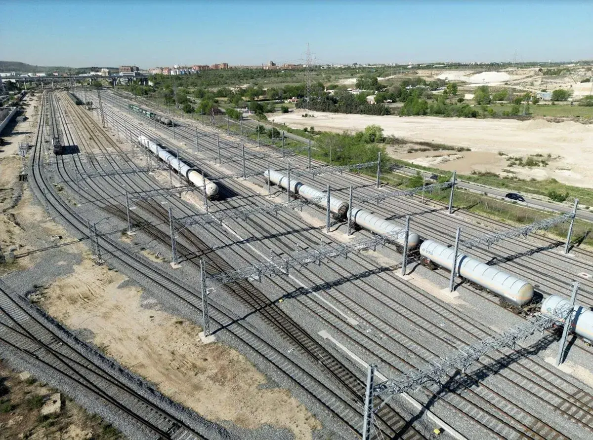
Chapter III. Freight Terminals: Classification
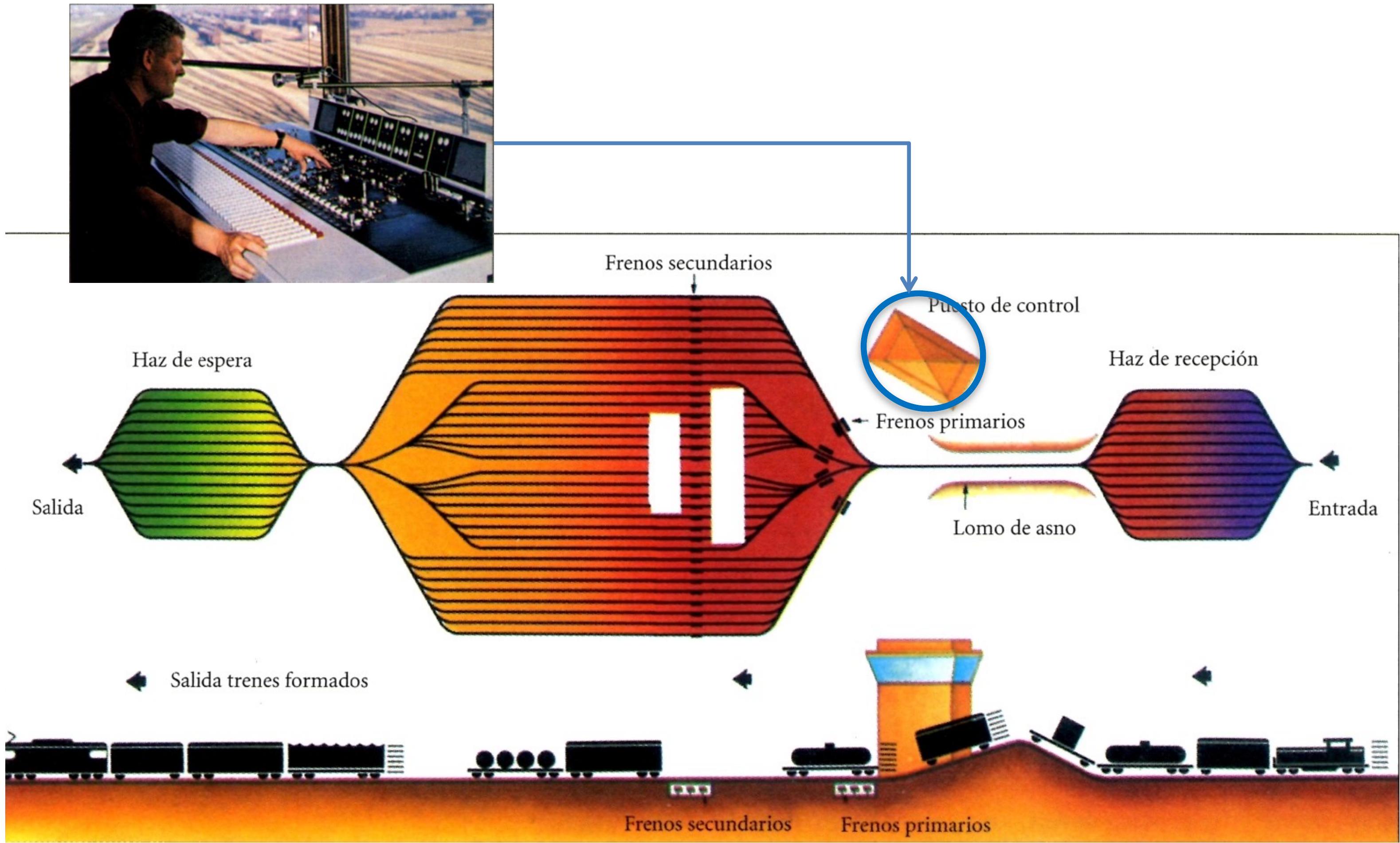
Freight terminals constitute specialized railway installations designed specifically for performing complex logistical operations. Their main function is to allow consolidation and deconsolidation of freight railway compositions, facilitating formation of complete freight trains by integrating wagons proceeding from multiple origins. This classification and ordering process is fundamental in freight traffic operation, allowing optimization of railway transport capacity utilization and facilitating freight movement from multiple origin points towards diverse destinations.
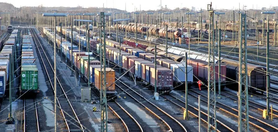
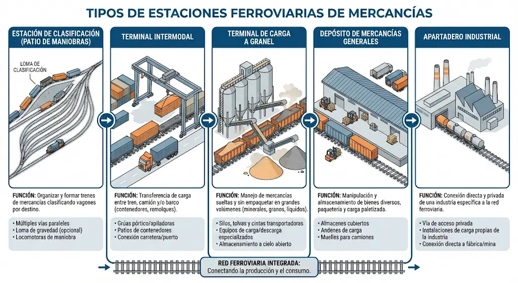 The following graphic documentation presents freight terminal typologies and configurations:
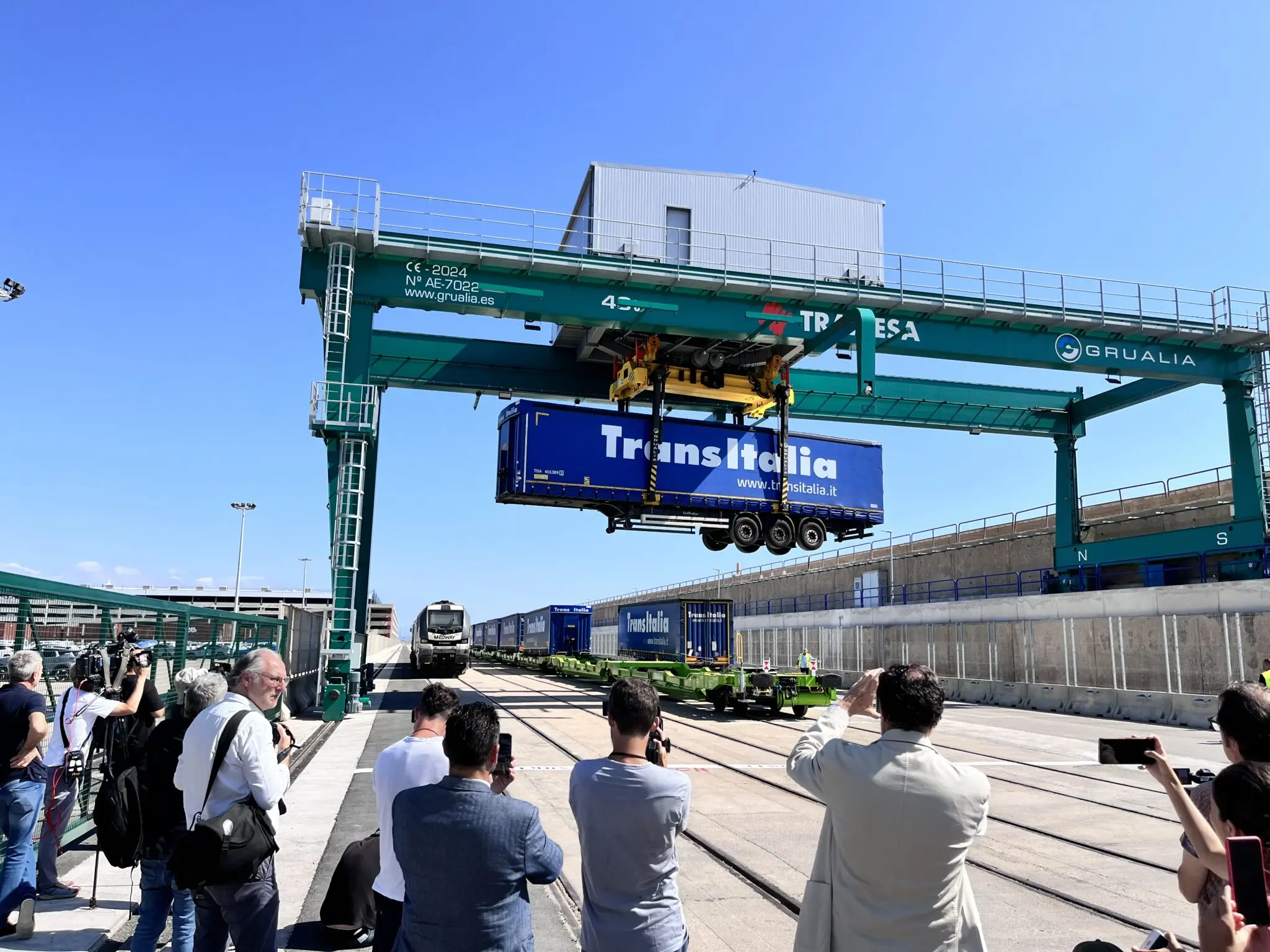
Chapter IV. Freight Terminals: Containers
Terminals specialized in container movement represent a significant evolution in contemporary railway logistics, allowing efficient intermodality between railway and road transport. The design of these terminals requires specific technical considerations and particular attention to handling equipment employed.
Railway Infrastructure Requirements
The configuration of tracks within railway sectors destined for container operations must be designed to allow both arrival and departure of complete railway compositions without operational interruptions. The length of the track sector equipped with the transshipment crane —structure rolling on rails parallel to compositions— typically extends between 200 and 500 meters when using two gantry cranes. The useful working width of a typical gantry crane usually does not exceed coverage of six parallel tracks, with a total span of approximately 25 meters width.
In the specific transshipment area, container exchange proceeds from private trucks, terminal mobile cranes, or directly from container wagons. To guarantee vehicle circulation and maneuver within this area, it is necessary to provide two turning areas or loops at the ends, each with a minimum diameter of 25 meters. The storage area must be designed to facilitate container mobilization operations; additionally, containers must be concentrated in storage blocks not exceeding 1,000 square meters each, maintaining wide separation strips between blocks as a measure to prevent fire transmission in case of contingency.
Handling Systems: Gantry Crane
The gantry crane constitutes the most frequently employed handling system in specialized terminals. This solution presents well-defined technical and operational characteristics:
Advantages:
- Requires small useful surface extension
- Provides high performance in transshipment operations
- Offers good visibility of operations for supervision personnel
- Absence of noise generated by internal engines (typically electric drive)
Disadvantages:
- Very high initial capital investment
- Rigid installation in terms of capacity (difficult to expand)
- Track capacity limited by crane configuration
- Scarce possibilities for reserves or operational redundancy
Handling Systems: Mobile Transporter
The mobile transporter (or Reach Stacker/Straddle Carrier) constitutes a flexible alternative to the fixed gantry crane, allowing greater operational adaptability:
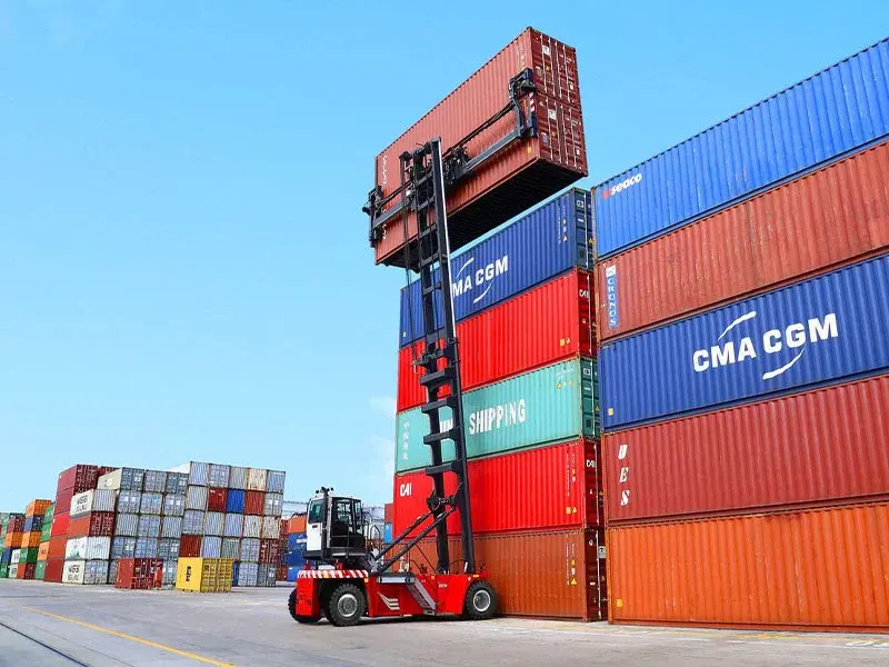
Advantages:
- Lower initial investments compared to gantry cranes
- Great flexibility to adapt to operational changes
- Better utilization capacity of multiple tracks
- Greater possibilities of reserve and operational redundancy
Disadvantages:
- Greater need for available useful surface
- Longer transport routes during operations
- Possible interferences between transshipment operations and services
- Poorer visibility conditions for supervision
- Generation of higher environmental noise levels
These two technological solutions represent the main paradigms currently, each appropriate for distinct operational contexts according to specific requirements of volume, flexibility, and land availability.
Review Questions
What is the clearance point (piquete de entrevía) and what implication does it have on track length?
It is the limit point between two converging tracks beyond which compositions would collide. Its position determines a loss of useful track.
What are the two main typologies of passenger stations according to their track configuration?
Dead-end stations (terminals where the journey ends) and through stations (which allow line continuity).
What difference exists between a lateral transversal (simple ladder) and a fan-shaped transversal?
In the lateral transversal, turnouts succeed on the diversion, while in the fan-shaped one they have the same hand or orientation.
What platform heights are standard in Spain for High Speed and Commuter services respectively?
76 cm for High Speed stations and 68 cm (or 96 cm in exclusive ones) for Commuter stations.
What are the main advantages of the Gantry Crane versus the Mobile Transporter in container terminals?
It requires less surface, offers high performance and better visibility, although it is less flexible and more expensive.
Bibliography
The following references constitute relevant consultation sources to deepen in the topics treated in this chapter on railway stations:
-
Díaz de Villegas, J.M. (2003) Ferrocarriles. Apuntes de clase. Escuela Técnica Superior de Ingeniería de Caminos, Canales y Puertos, Universidad de Cantabria, Santander.
-
García Álvarez, A. (2022) Manual de ferrocarriles. El sistema ferroviario español. Editorial Garceta, Madrid.
-
García Álvarez, A. (2011) Diseño funcional y técnico de estaciones ferroviarias para viajeros. Fundación de los Ferrocarriles Españoles, Madrid.
-
Official site of the Railway Infrastructure Administration (ADIF): https://www.adif.es/sobre-adif/conoce-adif/declaracion-sobre-la-red